On upgrade path: LR2 -> LR3, Clarksburg, WV, USA

@vicious1
Thanks. I guess I could cut these struts out of 1/8” hardboard in a single pass instead of multiple passes. I think what Barry said about not using an up-cut bit may help too.

1 Like

Planned changes to my SKR board case remix:

@vicious1
I got my SKR case done and after putting it together I realized that I would rather the lid not have a hole for cables but rather just stop short and leave an opening at the bottom, because as it is I had to route the wires through the lid before the lid was in place and then slide the lid on the wires to put it in place, and since my wires are inside a plastic wire hose which is a little too big for the hole it was a pain to put it in place. Then I had to take it apart and put it together a couple of times to get my motor directions right, and I’m gonna still have to take it apart and put it back together once I get to checking the end stops. So I think instead of having a hole in the lid for cables, I will just have basically an opening that leaves a gap at the edge so it’s more like a hollow place that allows the lid to the installed and removed without having to slide it along wiring.

Also, I’m going to turn the TFT holder back to same orientation as on my previous box on my LR2. That one had X- and X+ oriented with X axis, and Y- and Y+ oriented with Y axis. This one, as is, has them perpendicular, and although I can account for it in my mind, it make things slightly annoying. Plus, with my table designed like it is, accessing the buttons is not easy when I am standing on the X axis end of the table (screen is facing out away from me then). A 90 degree turn will correct all this.

1 Like

Report on “snap in place" lid feature I created on SKR case:

@vicious1
Above I posted about the “snap in place" feature I tried out. Reporting back that it works great. The very first time you snap it in/out, it seems too hard to snap, but as you know, PLA will give way a little, and by about the third or so snap in, it works as intended, and so I think 0.35mm for the bulge and the corresponding lip is just about right. I like this feature and will be keeping it.

1 Like

Screen shots of revised remix of V1 case CAD files for holding SKR Pro 1.2 main board & BTT TFT35-E3

LR3 control box case for SKR Pro 1.2 with TFT35 E3 — based on V1’s Blank Case CAD files

FREE STL FILES AVAILABLE HERE: Printables

…this time showing that I’ve turned the touch screen back like I had it facing on my LowRider 2 setup.

I feel I am close to being ready to share these on Printables.

1 Like

My newly revised case lid is now printed. Hope to assemble soon.

Also, just for a record here in my history, and that may be a help to someone else…

LowRider 3 Dual End Stop board pins while using pre-configured firmware (“V1CNC_SkrPro_DualLR_2209-2.0.9.2”) for SKR Pro v1.2 — Dual End Stops for LowRider

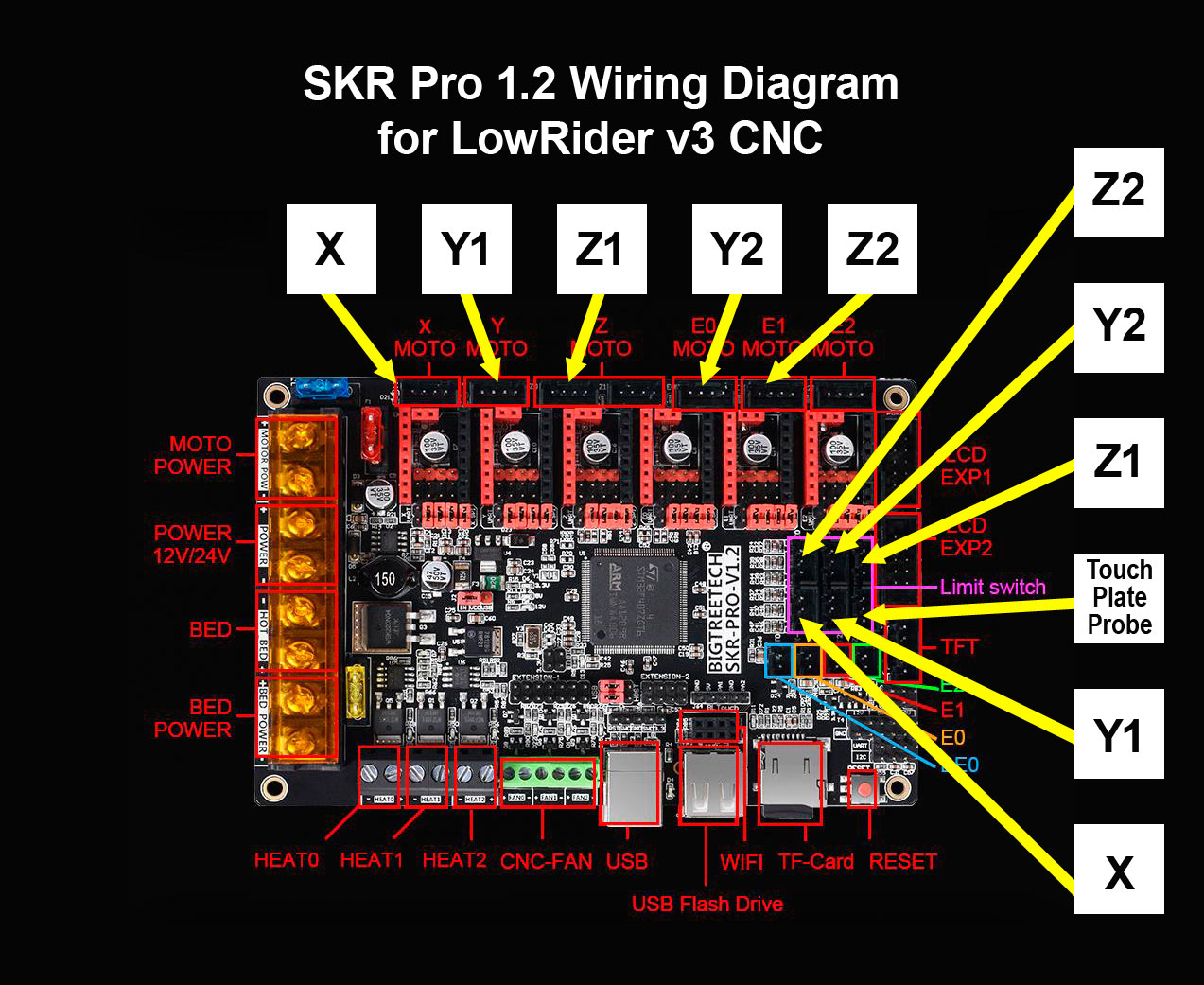
This is the pin configuration that finally worked for my end stops:

End Stop Connected to
X X min
Y1 Y-min
Z1 E2
Y2 E1
Z2 E0

And here is a graphic illustrating it:

3 Likes

Downcuts have their own quirks. They pack the chips into the cut, so you tend to need to move at a different pace. and can tear out the bottom if not held in place firm enough (thin material).

Rather than a down cut, I tried a straight bit (brand new). I tried that along with doing the cut in a single pass. I still got crazy tear out from the top. I guess either the hard board I bought is somehow different, or I’m just not using the right settings.

Going from memory, I think Z1 and Z probe are backwards there

What I have in the graphic is definitely working for me now.

1 Like

Ok. I’ll defer to someone who has it working. I had it workimg, but pulled it out for the Duet.

Got my SKR case assembled and mounted. Got my two additional Strut plates cut. Got one cleaned up (removed tear out). Will need to clean the other one, and then paint them both.

In the meantime, I’m transferring video to be able to show some cool stuff such as the SKR case assembly and show off.

3 Likes

New video, plus, got the new SKR case posted on Printables!

LR3 control box case for SKR Pro 1.2 with TFT35 E3 — based on V1’s Blank Case CAD files

FREE STL FILES AVAILABLE HERE: Printables

5 Likes

Me too. I had to come looking for an answer to an end stop issue this evening, and mine maps exactly like your diagram shows, not how it is written in the docs. Glad I’m not going crazy

1 Like

Did you flip the side the rail is on, compared to the pics on the Main LR3 splash page?

@Neilp

Yes, I flipped which side my Y rail is on! So, if you do not, you may not need the X end stop screw fix like I did.

Flipping which side the Y rail is on requires printing mirrored parts for the wheel corner attachments and their corresponding parts on the Y rail roller side.

Sorry, I did not think to mention that change explicitly in earlier posts.

Compared to the front of the machine, you still want the homing to be to the left, so unless you also flipped either the XZ plates or the stubs for milled parts, as well as the core, homing will still be to the same side, and therefore the larger dust collection part will still interfere with X homing without the long screws.

This image should help explain what I meant:

1 Like

LR3 Cable chain mount - printed parts

I really like the LR3. It is a truly impressive design. My specific situation is such that I have needed to make a few minor tweaks to the plan.

The normal plan is for clever use of the vac hose — having it serve as the cable guide for the router’s power cord and X axis wiring. However, since my dust collection hose comes down from overhead, I’ve had to install a cable chain for guiding the power cord and X axis wiring. Since that is outside the normal plan, I had to design up a handful of printed parts to mount the cable chain. I now have my designed parts printed and installed. If anyone else would benefit from the designs and wants them, they are here:
https://www.printables.com/model/223004-lowrider-3-cnc-cable-chain-mount-v10

Overview:

Looking down on the upper mount setup:

Birds eye view of the upper mount setup:

This little clamp-on piece holds the router cord secure so it does not bump against the side assembly when X axis is tight against home:

Close up of lower mount part:

@Neilp

See above. Since (I think) you said you are using a dust collection system, I’m not sure if the above would benefit you, but maybe. STL files are here:
https://www.printables.com/model/223004-lowrider-3-cnc-cable-chain-mount-v10

Maybe you and @DougJoseph can look at the docs now and see how to improve them. This is from the docs:

At first glance, it looks wrong compared to the diagram above, but the driver column is mean to point out which driver good to which motor. The endstop communion is right (afaict). The skr pro board labels xmax, ymax and zmax as E0,E1,E2, but that is a bit irregular.

Maybe I need another column for the skr endstop names?