Just for my FI, what is the actual purpose of adding a resistor and how would it have kept things alive? And if it was needed, was it an oversite that the boards went out without them or was it an issue that popped up later?
It’s been updated since it was shipped, the low mem message went away briefly but has been alive and well for a while. I just lived with it. I don’t recall what version I was last on, but it was not the brand new apparently, but the version before.
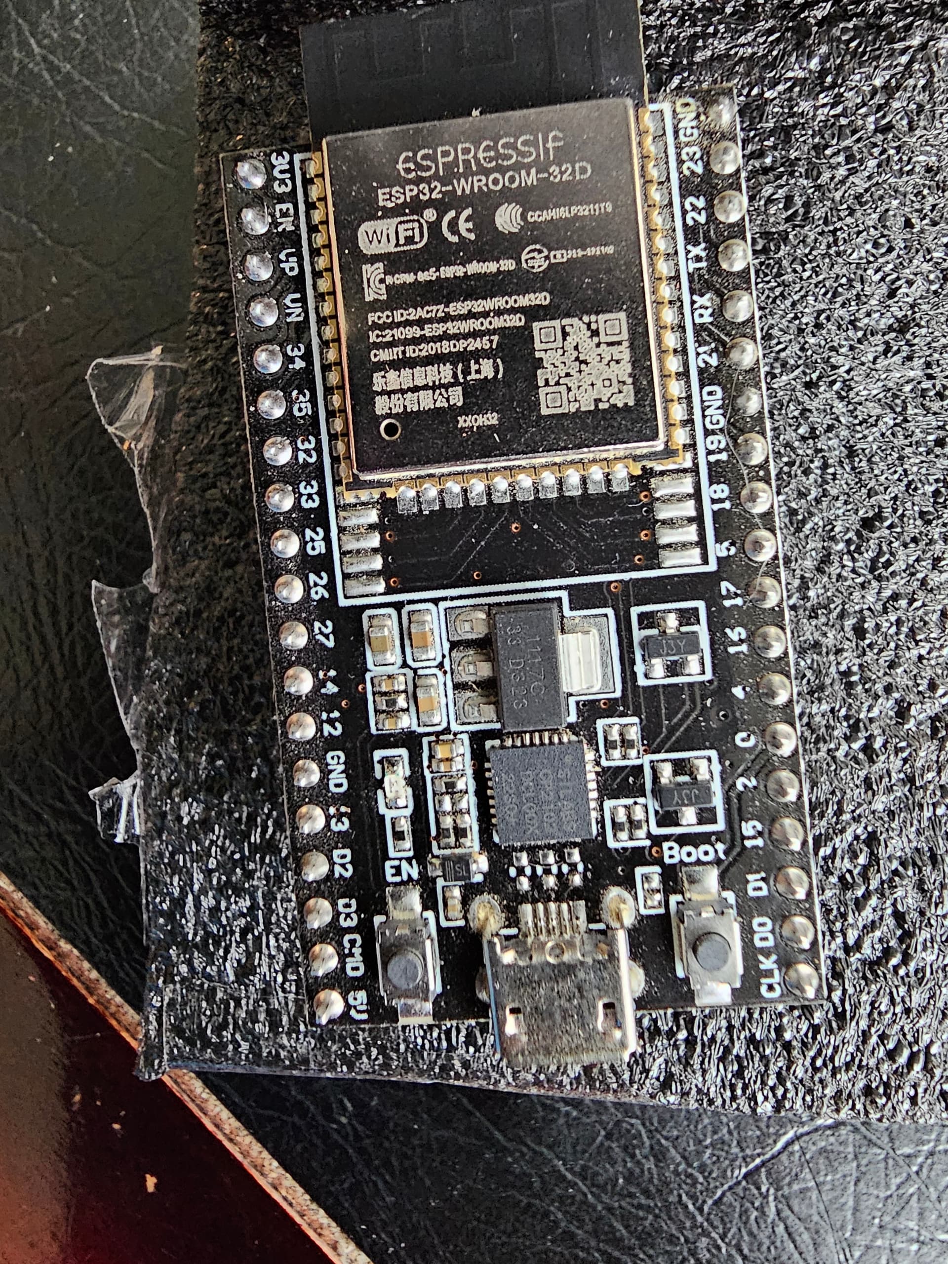
The ESP-32, and specifically the ESP-32 chip on the dev board, is the brain of the whole output. The FluidNC firmware runs there in the two processor cores, and the WiFi and Bluetooth hardware live in that chip.
There are variations among ESP-32s, and depending on who built the dev board and how well they spec’d coponents or made modifications, some work great, some not as well.
The ESP-32 has a pin that does double-duty. At boot time, this pin (BOOT0) tells the ESP-32 whether to load user firmware, or to enter the boot loader. After boot time, this pin is used as a UART, and that UART talks to the TMC2209 drivers to configure them.
On some boards and in some circumstances, the weak pull-up inside the ESP-32 chip is inadequate, and the results could be that user firmware never boots, or potentially the board can’t be put into boot loader mode without the user pressing some buttons on the board.
Additionally, if the pullup resistor value isn’t well chosen, that pullup resistor will interfere with the communication between FluidNC and the TMC2209s after the firmware is running.
This was discovered early in the Jacpot release cycle as some ESP32 dev boards were failing test, or users like me tried different versions of dev board and found them not to work. (I used a USB-C version, for example). We had a lengthy troubleshooting/test thread here on the forum, and there were two results-
- A pull-up resistor was added to the jackpot board design.
- Ryan designed his own ESP-32 dev board so he could control cost and quality of the parts he was using.
You want to be on 3.8.0 at this point. We can sort that out when you have whatever ESP-32 you want to use long term.
1 Like
You need to PM me the email you used. What was your choice what did you want me to do?
I was just going to mail it to you to try the resistor. Or throw it away if it’s trash ![]() I’m guessing you’ll be better capable of determining if it is or not.
I’m guessing you’ll be better capable of determining if it is or not.
I will take care of it, I just need your info. You have a v1.2 so you already have the resistor, do not add another. I got your thread confused with another. (ps the test is just htting the reset button 10 seconds or so after powering it up). If it boots it was a resistor issue.
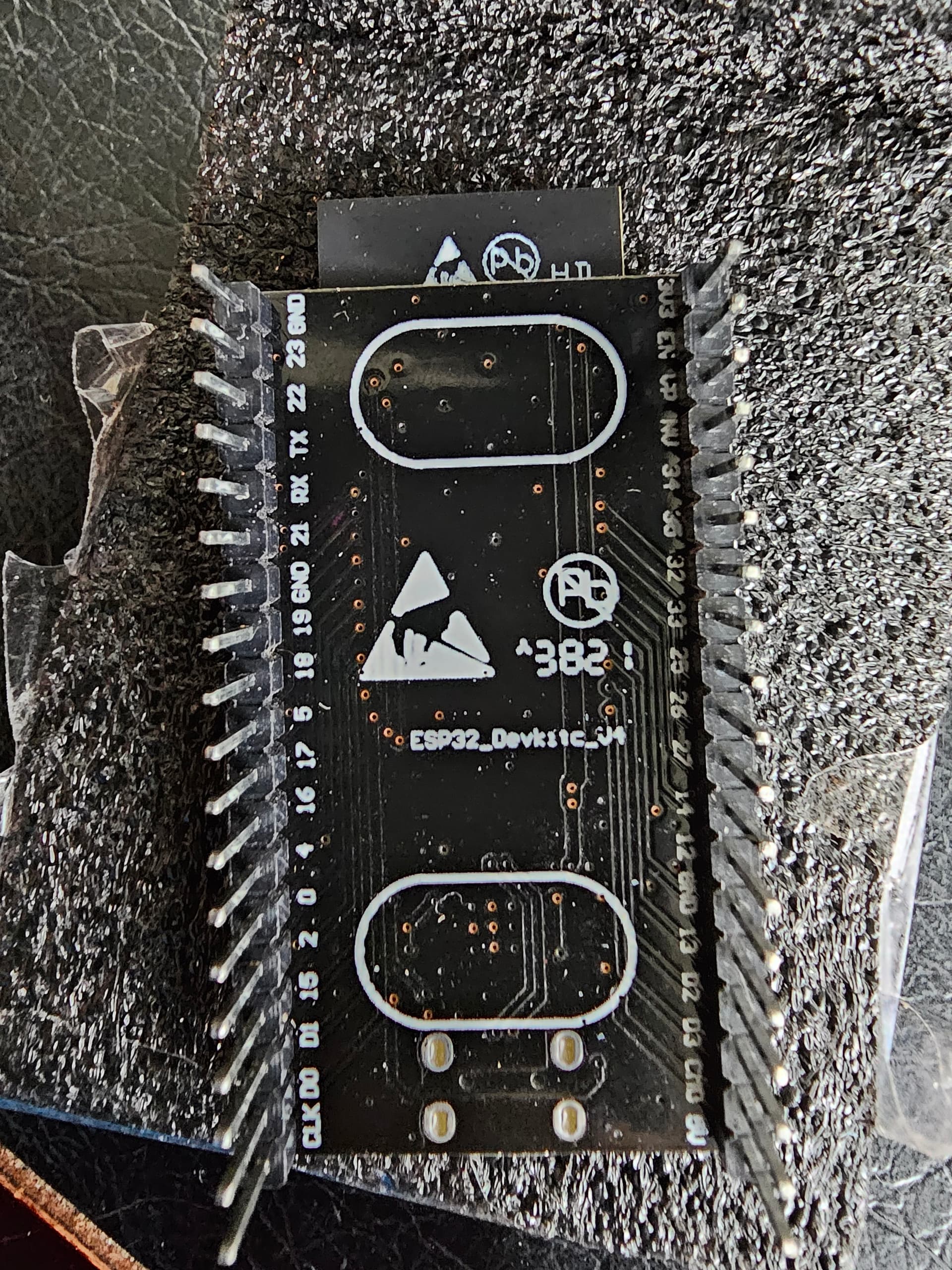
Kinda looks like you have a genuine ESP32 as well but I need to see the underside of it to be sure.
If you do have a genuine I will need to get both back in here for testing to see what is wrong. This would not be a common scenario. We have only had the generic ones fail after the fact.
He said so just one post above.
Ok, something different tonight.
I pulled the board to get it ready to box up and ship before I leave town. As I’m sitting at my desk the earlier remark of [sic] “you have 1.2 so the resistor is already there.” flashes so I decide to put the esp back in the board and try again. I’d been assuming the needed resistor was on the chip, but thought I might have been reading it wrong and it was on the board.
So back together, power, hold boot for 30 seconds, reset for 20, release the reset and 10 seconds later release boot.
I tried the windows erase, and fails with the header message. I tried the windows, and it connected with the " There was an error during boot, likely due to an unvalid configuration.
Click here to see details" message.
I’m unaware what ‘unvalid’ means but it’s not my place to worry about typos. Anyway over to the file section and it allowed me to upload the v3 yaml file. So that was new. I wiped it and downloaded the v2 files, and it took them all.
So reboot it again, and it appears to boot again with the same unvalid messange. Details:
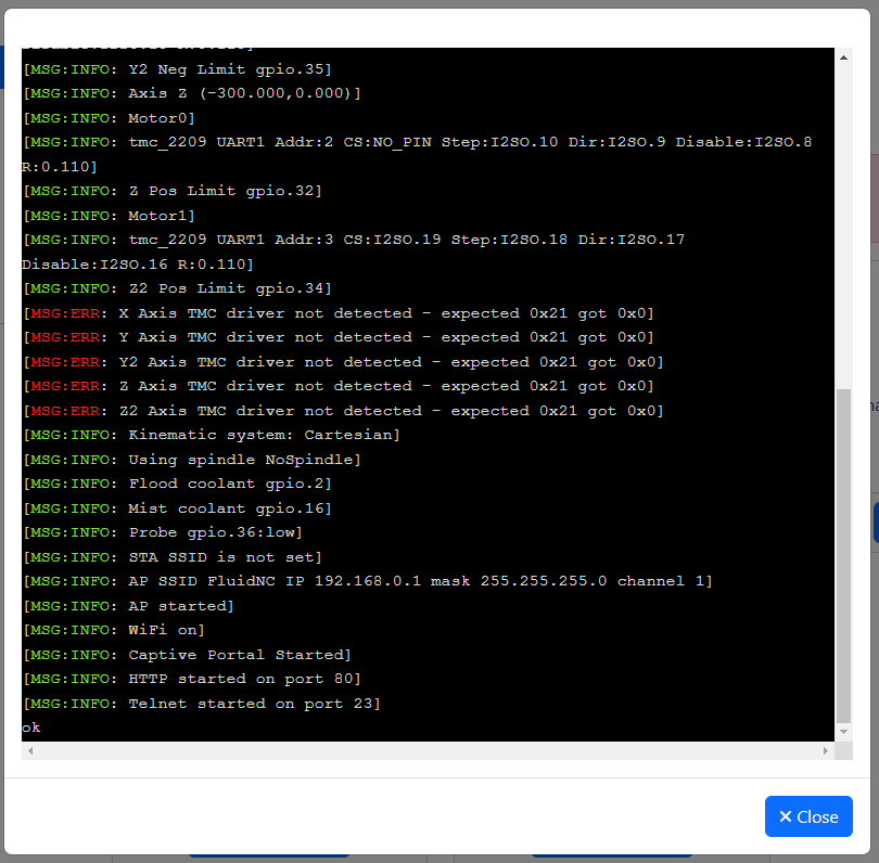
"[MSG:INFO: FluidNC v3.8.0 GitHub - bdring/FluidNC: The next generation of motion control firmware]
[MSG:INFO: Compiled with ESP32 SDK:v4.4.7-dirty]
[MSG:INFO: Local filesystem type is littlefs]
[MSG:INFO: Configuration file:config.yaml]
[MSG:INFO: Machine LowRider]
[MSG:INFO: Board Jackpot TMC2209]
[MSG:INFO: UART1 Tx:gpio.0 Rx:gpio.4 RTS:NO_PIN Baud:115200]
[MSG:INFO: I2SO BCK:gpio.22 WS:gpio.17 DATA:gpio.21]
[MSG:INFO: SPI SCK:gpio.18 MOSI:gpio.23 MISO:gpio.19]
[MSG:INFO: SD Card cs_pin:gpio.5 detect:NO_PIN freq:20000000]
[MSG:INFO: Stepping:I2S_static Pulse:4us Dsbl Delay:0us Dir Delay:1us Idle Delay:255ms]
[MSG:INFO: User Digital Output:0 on Pin:gpio.26]
[MSG:INFO: User Digital Output:1 on Pin:gpio.27]
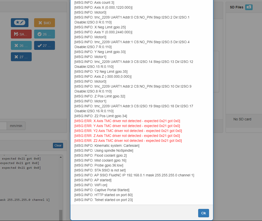
[MSG:INFO: Axis count 3]
[MSG:INFO: Axis X (0.000,1220.000)]
[MSG:INFO: Motor0]
[MSG:INFO: tmc_2209 UART1 Addr:0 CS:NO_PIN Step:I2SO.2 Dir:I2SO.1 Disable:I2SO.0 R:0.110]
[MSG:INFO: X Neg Limit gpio.25]
[MSG:INFO: Axis Y (0.000,2440.000)]
[MSG:INFO: Motor0]
[MSG:INFO: tmc_2209 UART1 Addr:1 CS:NO_PIN Step:I2SO.5 Dir:I2SO.4 Disable:I2SO.7 R:0.110]
[MSG:INFO: Y Neg Limit gpio.33]
[MSG:INFO: Motor1]
[MSG:INFO: tmc_2209 UART1 Addr:3 CS:I2SO.14 Step:I2SO.13 Dir:I2SO.12 Disable:I2SO.15 R:0.110]
[MSG:INFO: Y2 Neg Limit gpio.35]
[MSG:INFO: Axis Z (-300.000,0.000)]
[MSG:INFO: Motor0]
[MSG:INFO: tmc_2209 UART1 Addr:2 CS:NO_PIN Step:I2SO.10 Dir:I2SO.9 Disable:I2SO.8 R:0.110]
[MSG:INFO: Z Pos Limit gpio.32]
[MSG:INFO: Motor1]
[MSG:INFO: tmc_2209 UART1 Addr:3 CS:I2SO.19 Step:I2SO.18 Dir:I2SO.17 Disable:I2SO.16 R:0.110]
[MSG:INFO: Z2 Pos Limit gpio.34]
[MSG:ERR: X Axis TMC driver not detected - expected 0x21 got 0x0]
[MSG:ERR: Y Axis TMC driver not detected - expected 0x21 got 0x0]
[MSG:ERR: Y2 Axis TMC driver not detected - expected 0x21 got 0x0]
[MSG:ERR: Z Axis TMC driver not detected - expected 0x21 got 0x0]
[MSG:ERR: Z2 Axis TMC driver not detected - expected 0x21 got 0x0]
[MSG:INFO: Kinematic system: Cartesian]
[MSG:INFO: Using spindle NoSpindle]
[MSG:INFO: Flood coolant gpio.2]
[MSG:INFO: Mist coolant gpio.16]
[MSG:INFO: Probe gpio.36:low]
[MSG:INFO: STA SSID is not set]
[MSG:INFO: AP SSID FluidNC IP 192.168.0.1 mask 255.255.255.0 channel 1]
[MSG:INFO: AP started]
[MSG:INFO: WiFi on]
[MSG:INFO: Captive Portal Started]
[MSG:INFO: HTTP started on port 80]
[MSG:INFO: Telnet started on port 23]
ok"
Everything is green except the xyz drivers are missing and those error messages are in red. If that’s referencing the driver chips, they’re all installed. And the error message was talked about as being because the config file was not installed, but it is definitely there now.
So 1st question. I’ve been doing all of this with the esp on my desk, I distinctly remember it being recommended to pull it from the board. But did I mis-read that and I’ve actually supposed to have been doing all of this with the esp in place?
2nd, assuming It’s actually connecting correctly to this point, where am I actually sitting with this being functional? I don’t have a lot of time before I’m on the road and I don’t want to put everything back together just to pull it apart again.
I was having regular connection issues before it just failed entirely. The working/not working feels to me like a hardware issue.
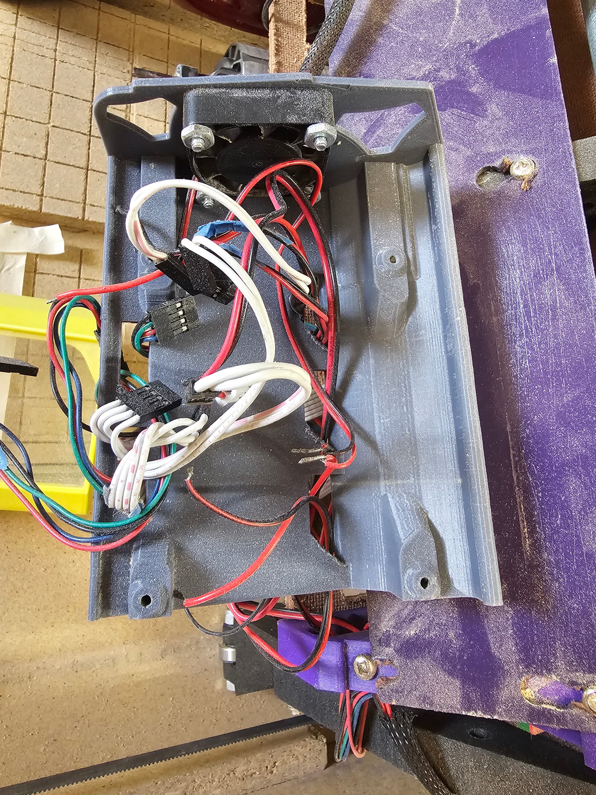
The stepper drivers and rest of the electronics on the Jackpot do not work if the board is only being powered by USB.
The real test is with the Jackpot connected to VMOT (Jackpot board) power.
If it boots and comes up reliably in that configuration then the board is working.
That was going to be my thought as well.
Running on usb I could connect by wifi and got to the control screen, and the same driver errors.
Everything else looked normal.
Few things make me more nervous than doing absolutely nothing productive to fix a problem, and then have things start working for no apparent reason.
2 Likes

It’s found a new way to not work. Clever little thing.
The way I debug those is to run FluidTerm while testing. I’m not sure what exactly happened, but it looked to me like there was some kind of issue when homing to Zmax, that cause a crash/reboot.
Your 2nd connection showed you the crash dump, FluidTerm would have caught that in real time (and be cut/pastable).
I’m back in town, downloaded fluidterm and got “can’t run on this machine” :laugh: this thing is going to give me an ulcer ![]()
Ugh. Always something ![]()
Can you post the whole output?
Tell me again what kind of computer you are using?
I’m glad I’m doing this as a hobby and not a business, it takes all the pressure off since I can just walk away. Of course now a week later, a few thousand driven miles and sadness since I dropped my kid off at college… now I have to remember where I was at when I left off because I know I had it moving and irritating me in a new way before I left.
So windows pc, old laptop.
Going from memory, I got the esp to take the flash once i had it back on the jackpot. It was moving but the probe function was not working at all, tab is up but telling it to probe did nothing. I need to look up what the grbl command is and just do it manually.
Setting z 0, it for some reason is cutting air.
And before I was getting pin activation using the mist button to turn on the router. None of the buttons do anything. M7 in gcode isn’t working but command input m7 fires it up. That doesn’t make sense to me so I need to verify it’s in the code.
I loaded everything with the v2 downloads, I’m guessing there is just some missing commands on the buttons but I haven’t put any time into it. I gave up and hit the road.
I reset the Z steps per mm because me leadscrews are different so it appears correct.
I’ll have some time later today to try and work on it again and try to get back up to speed. It was working fairly well until the whole communication thing.
Ok, running it briefly and apparently a week off of power didn’t magically fix things. Powered on, homed 3 axis, and 30 seconds later right back to no response to commands.
I believe it’s going in a box and being sent in to be looked at. Maybe we need to bring in a priest and do an exorcism on it…
What was plugged into the 5v and mosfet ports? It tests fine on my side, been sitting at a very cool temp everything seems to work as expected?
I have a laser pointer on the 5v, mosfet is a 24v/110 relay for the router control. It sits elevated with a cooling fan that’s hooked into the main, so it’s on whenever the machine is powered on, the only contact is the screw posts.
It’s been wired up this way since the beginning.
Whenever it stops responding leds are still lit and appearance wise or loss like everything is on and normal. When it had stopped resounding during use, it keeps working normally until the cut is dobe, so it’s still processing the gcode normally, but then it just ignores everything until in powered off and back on.