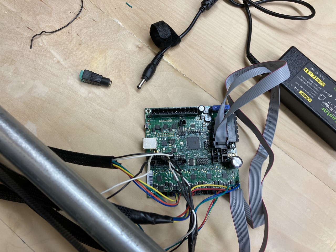
I purchased the MPCNC full kit with end stops back in January but I had to put it on the back burner for a couple of months. I finally finished my build and I’m ready to power up but I have a couple of questions. It came with a 12V 3A power supply but I can’t tell where on the RAMBO v1.4 board to connect it.
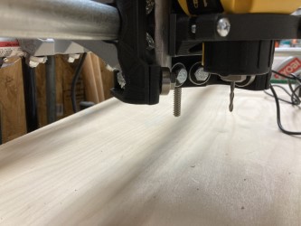
Also, the Z-axis threaded rod wound up being a little longer than my router bit. Am I supposed to cut it off?
One last thing. Is the firmware that came on the RAMBOv1.4 correct for my setup or do I need to change it? I know very little about this sort of thing.
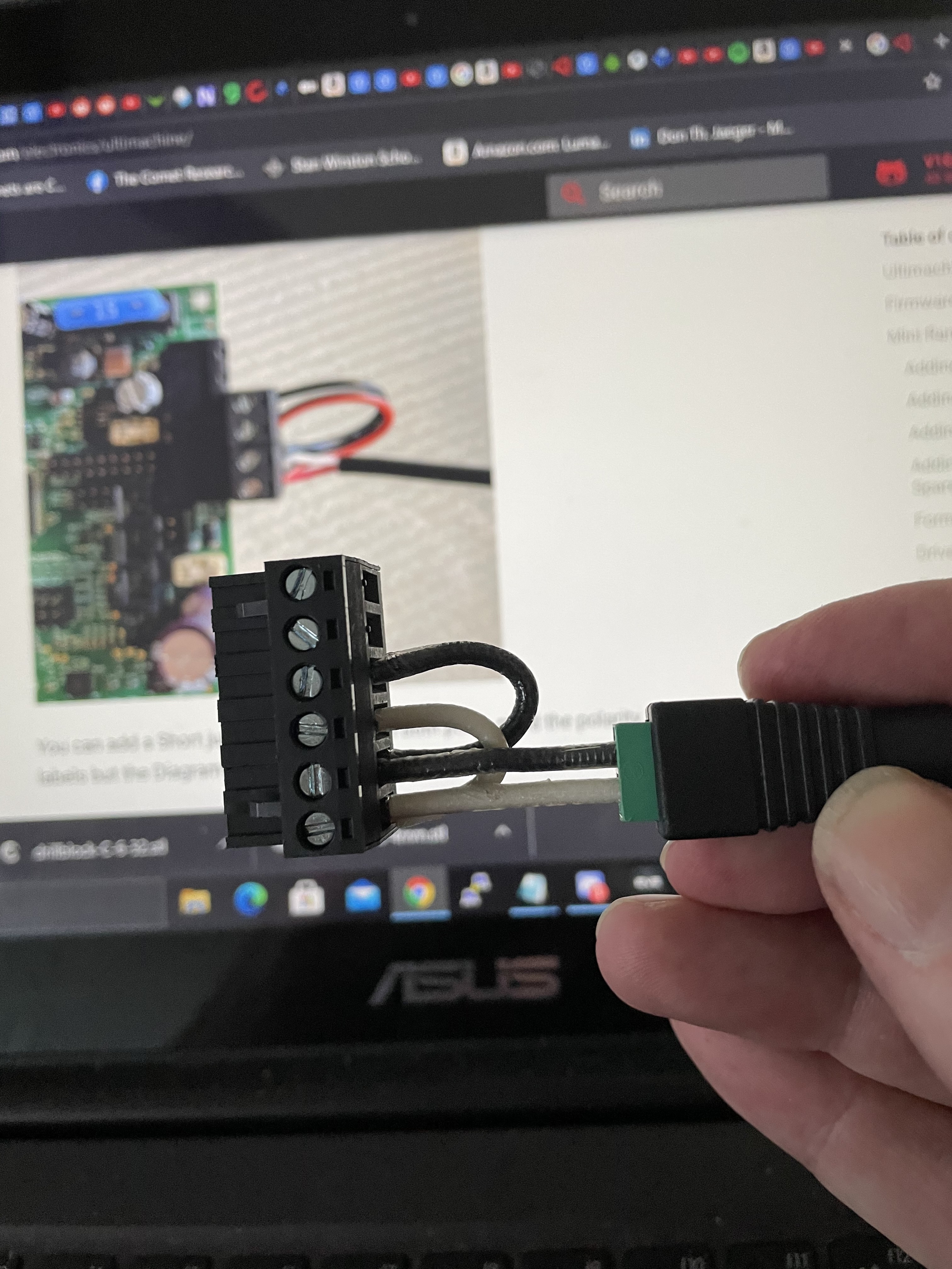
The documentation on this is not all that clear. You do it this way (but can use thinner 18 awg wires). Alternately you can cut the connector on the low voltage side of the power supply and connect directly to the motherboard.
Note + needs to go to 2 inputs on the motherboard and - also to 2 inputs.
More discussion in my build thread when I ran into this and other forum members provided helpful comments.
I also ran into the z rod too long issue and yes you cut it off if you want to use the full z axis range the machine can support without crashing into the table. I used a hack saw to shorten mine.
Note that the z screw only has to be long enough to engage the nut at the lowest desired position. The offcut of mine is quite long and I’m considering using it on another machine. Or possibly building a second Z axis that could be quickly swapped in.
Ok, so I got the power connected, a green light on the board and the display lights up but there’s nothing on the display. Sorry for being a dummy but I don’t know what to do next.
When assembling my machine it was helpful to find a forum post that it was harmless if the LCD cables were reversed or put on the wrong set of headers and you could use trial and error to get it working.
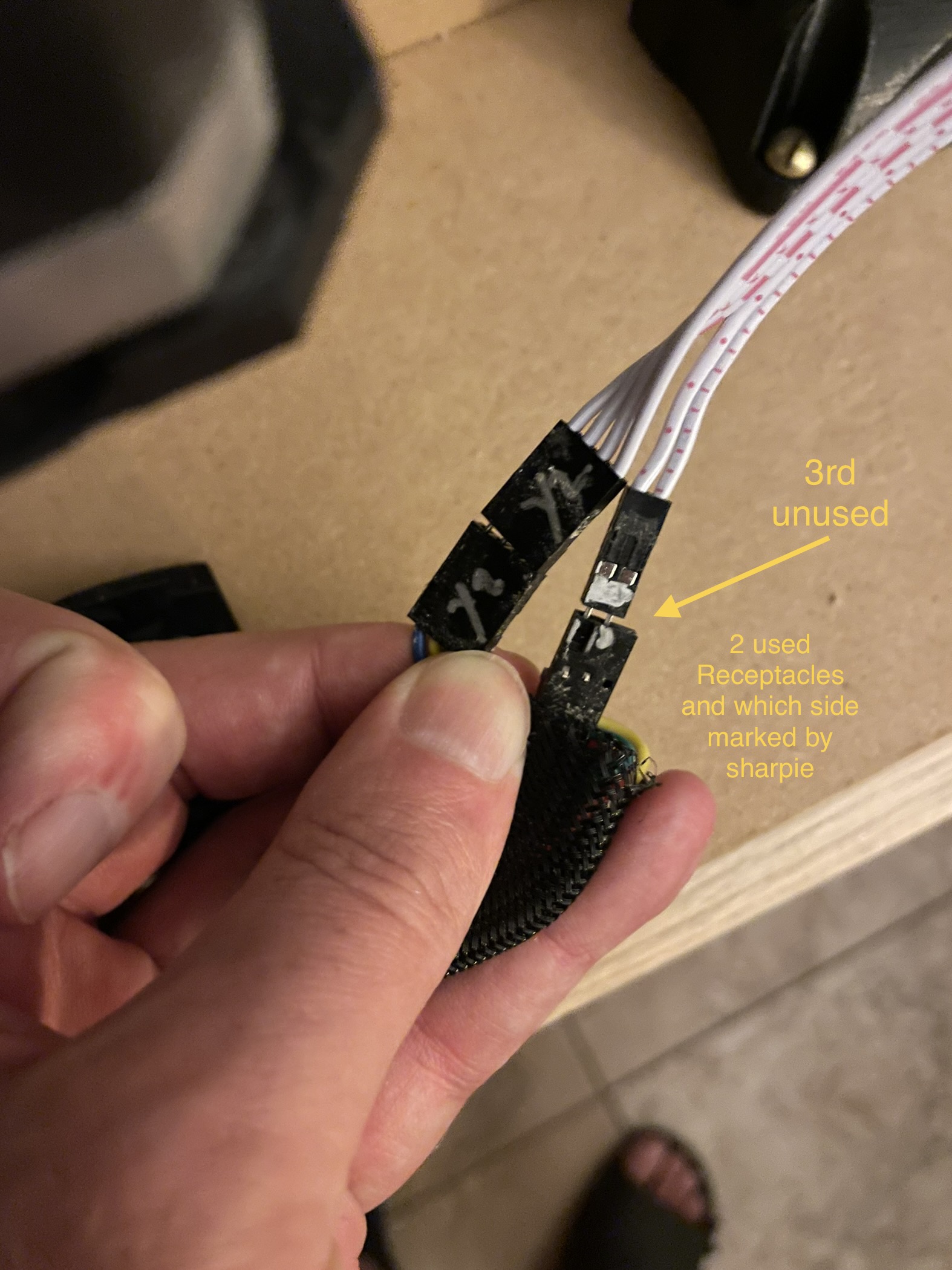
Also when doing the other wiring I used a silver sharpie to mark the black cable ends x1, y1, etc… and the end stop cables so you’d know which 2 pins to connect and which one to ignore as you connect the two and 3 wire cables together.
I marked both ends of the ribbon cable - the end that connects to the stepper motors and the end that connects to the Rambo control board.
The screen is probably wired wrong. The keys on the cables aren’t always installed the right way. You can try swapping them, or rotating them (rotating would need to cut off the key).
Makerbase boards and the LCDs key the 10 pin ribbon cables for the LCDs the other way from the actual RAMPS boards. I was under the impression that the RAMBo board is the same as the norm, so the cables should be keyed normally for the RAMBo and most LCD controllers, unless it’s a MKS LCD controller, in which case, it will be backwards. Fortunately, it doesn’t seem to do it any harm. I cut they keys off of one end of the cables with a chisel, but you can apparently change the housing around.
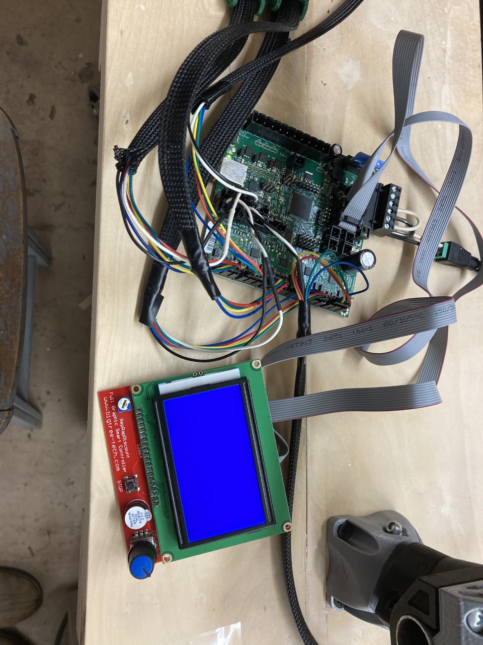
I’m pretty sure my ribbon cables are connected right, the red is on pin one, the display lights up. I ordered the Rambo v1.4 and Full Graphic Smart Controller from V1 engineering and the documentation says the correct Marlin firmware is already installed. I changed my wiring for dual end stops and it looks like I’m supposed to use the MPCNC_Rambo_Dual firmware from this link: https://github.com/Allted/Marlin/tree/V1CNC_Rambo_Dual but I don’t see what to click on to download it and what I’m supposed to do with it. If I click on “Go to file” it has a long list of files that I haven’t a clue what to do with. I’m completely in the dark here and I need some more specific instructions. I’m using this strictly as a router, I already have an Anycubic MegaX printer.
Sorry for the delay, I just got back to working on this.
“Try just disconnecting the gray cables. Leave the black serial ones installed”.
I don’t understand what you mean. The gray ribbon cables are the only ones going to my display. If I disconnect them the display won’t work. I don’t have the usb connected to my computer yet. Do I need to insert an SD card into the lcd display to get my gantry to move and if so what do I need to install on the sd.
I think the “unhook the gray cables” instruction is for a different controller ( touch screen) than is in your photo. If when you power things up there’s no image on the display you can try swapping the gray cables but it looks good to try in the picture.
Once the controller starts up you’ll have menu options for moving the axes around.
Other folks have had problems with the barrel connector screw adapter, so you might consider just stripping the power supply wires and connecting them to the controller screw terminals if you have trouble.
If the buzzer is too quiet you can take the white label off.
I have the cables plugged in with the red wire on pin 1. I tried swapping the cables and the buzzer makes a clicking sound and the display doesn’t come on but flickers with each click. I tried turning the cables around with the red wire on pin 10 and now the display menu comes up. Now I am able to move x,y, &z axis steppers but steppers x2 & y2 which I have connected to E0 & E1 are not moving with them.
Try adjusting that and see if it helps, or actually makes a difference. It should cycle between clear, blank blue to showing all of the pixels as solid white dots. Naturally, you want it somewhere in between. If you short the trimpot, say by putting the controller down on top of a screw, the trimpot can get damaged. It can’t handle much in the way of current, and seems to be one of the most delicate things on the circuit board. This is why you cycle it to make sure that it does make a difference.
I’m wondering if I should have run both x steppers on the x connector and both y steppers on the Y connector or would that be too much of a load for those board connectors?