MPCNC build in Florida

I’m building a MPCNC starting with mostly default settings. I’ve used CNC routers in the past, but never built one. I thought I’d create a thread to log what I learned from it and hopefully it helps someone else and the V1 team with the next version or can improve the online documentation.

For the build process, the documentation has been mostly excellent. The photos were particularly helpful because there were many times I assembled something incorrectly and was able to identify the error with the photos. I found the documentation of the electronics and software parts less straightforward but have gotten a working machine.

The highlights of lessons learned so far:

  • I wish all the 3d printed parts had unique numbers (or other identifiers) embedded in them, like they have the C/F/J identifiers, and at times I was craving a corresponding exploded diagram from the CAD . I was able through trial and error to get all the right parts and get the machine assembled, but being able to match the text of the build instructions with uniquely labeled parts would have been helpful.
  • Either I overlooked them or the instructions didn’t have a step to cut the belt into the lengths recommended by the calculator as part of the truck assembly and before being asked to thread the belt through the truck.
  • Either I overlooked them or the instructions didn’t have a step to cut the lead screw from the default length to the length of EMT conduit used in the Z axis assembly.
  • I found the squaring process challenging. I had to revert steps, disassemble the machine, and try again a couple times. After assembly there was interference where you couldn’t get access to the squaring bolt with socket on both sides (or even a regular wrench) and sometimes I was using a socket on 1 side and a pair of needle nose pliers on the other. That worked but put damage and wear on the bolts but worked. I’ll post some pictures and maybe someone can tell me if I overlooked “the better way”.
  • I wish the documentation was more clear about whether the 7inch-lb spec was “nice to have” or something critical I should definitely buy a special tool to measure and guarantee. Amazon has something. That force level is smaller than the tools I could find in retail shops could measure - most were for auto use in ft-lbs.
  • I ordered a Rambo 1.4 from V1 as part of a dual endstop kit as Rambo seemed the most commonly used / best supported board. The V1 firmware was pre-loaded but not the dual endstop version. It would have been helpful if there was a paper note included with the package telling me which firmware build was factory installed (regular/dual, version#) and that I needed to go get and re-flash it for dual endstop support. I eventually found a forum post that noted the regular firmware M119 reported x, y, z where the dual endstop firmware reported x1, y1, x2, y2, z… Once I understood I needed to change the firmware and later had downloaded and compiled the right firmware I was able to troubleshoot the wiring successfully. With the wrong firmware I had problems like wiring everything same as the photos, but having the software report TRIGGERED endstops when they were open. I also had it activating one not both steppers in the X or Y because I’d wired it according to the dual endstop instructions.
  • The endstop wiring was clear to use the - and S pins. I wish the wiring instructions had told me if it was dangerous or harmless if I had the polarity reversed on the endstop wires. There were many references to wiring it for open vs closed without examples of what the connections would like like either way.
  • The Rambo photo was not clear whether to use the left or right Z connector when MPCNC has 1 Z stepper. (3rd or 4th from the left) I used the 3rd and that seemed to work.
  • It was helpful to find a forum post that it was harmless if the LCD cables were reversed or put on the wrong set of headers and you could use trial and error to get it working.

I did the initial wiring without the LCD connected, so an LCD message regarding which firmware would not have helped me. If there was a G or M code that printed a firmware version/identifier string I could have been asked to enter as part of the instructions to confirm I had the right firmware before proceeding, that would have been helpful.

  • I couldn’t initially power up the Rambo board correctly because it needed wires that were not included to connect between the green power supply connector jumper block, and the 6-wire jumper block that plugged to the board. Since wires are not included, I wished the documentation included a spec for what gauge of wire to use. ( The web docs did show how to wire the power to both the logic and steppers. Thanks! ) I’m not an EE and it took some internet research to understand what range of wire gauges would be acceptable.

More with pictures later in the thread.

5 Likes

I built the table on a steel cart from Harbor Freight.

2 Likes

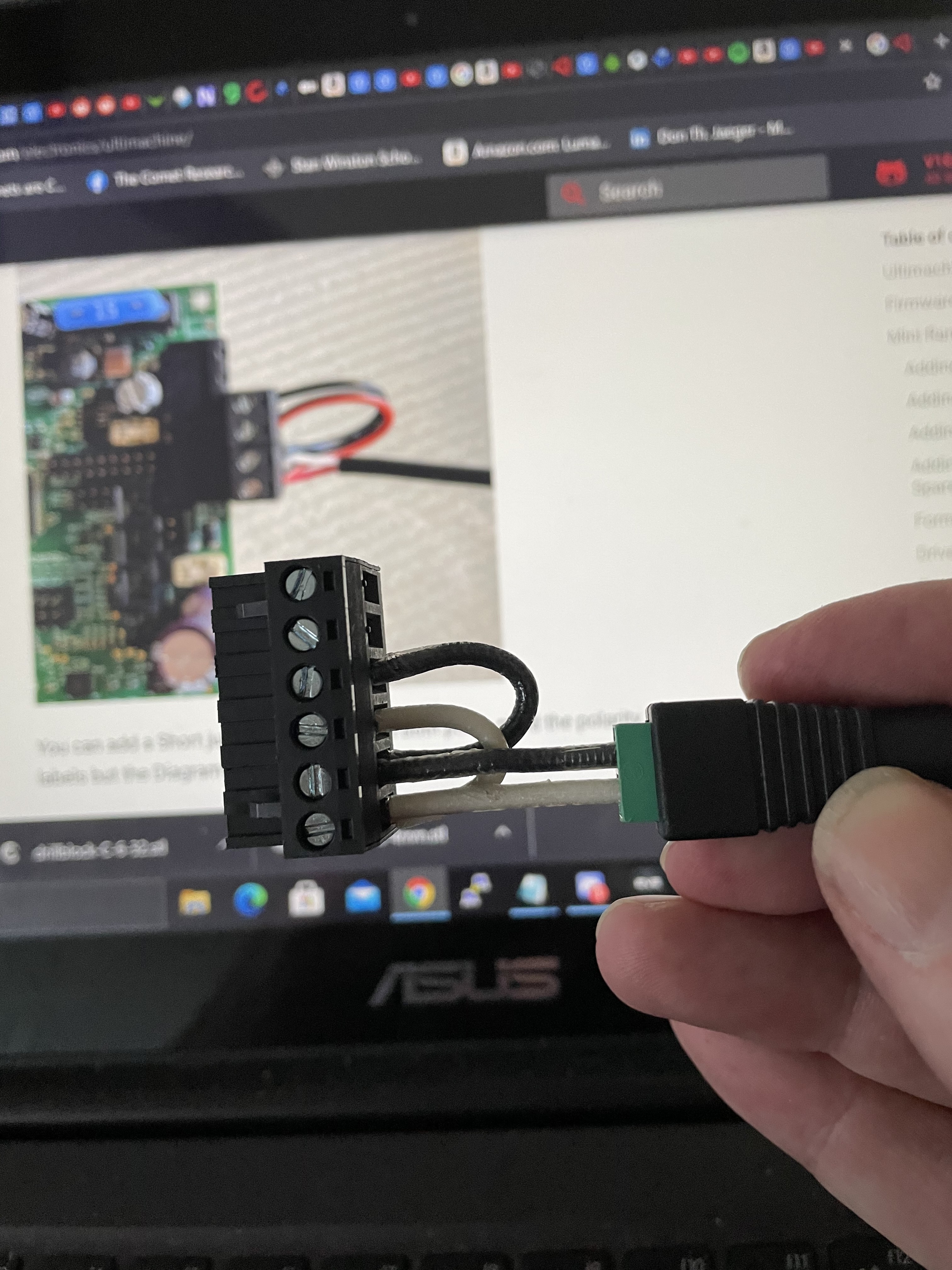
This is a photo of the wires that needed to be added to power the Rambo board. I used solid core 14 or 16ga wire.

I wish all the 3d printed parts had unique numbers (or other identifiers)… I was craving a corresponding exploded diagram

Yep. I was wishing for both of these when I put together my first machine (Burly). When building my Primo, I labeled each part with blue painters tape as it came of the build plate, but you had no way to know to do this.

Either I overlooked them or the instructions didn’t have a step to cut the lead screw from the default length to the length of EMT conduit used in the Z axis assembly.

I believe the cut calculator gives the length to cut the lead screw, and it can be significantly shorter than the Z tubing. And if you really matched the Z tubing length, the lead screw will hang probably 25mm below the Z axis assembly. You don’t want that. Personally I left my lead screw longer than the cut calculator specified. When adjusting the Z height by hand, it is sometimes helpful to just reach under the core and turn the lead screw from the bottom, plus if you end up changing leg the leg height (like I did twice on my Burly), you don’t have to cut a new lead screw. The only downside to a long lead screw is a small amount of additional mass to be moved around.

I wish the documentation was more clear about whether the 7inch-lb spec was “nice to have” or something critical I should definitely buy a special tool to measure and guarantee.

Nice to have. It works with a variety of tension settings on the looser side, and I expect few would own or acquire a tool.

The V1 firmware was pre-loaded but not the dual endstop version.

Based on comments on the forum, Ryan looks at the supplies your purchase to determine what firmware to put on the board. So if you purchased a dual endstop wiring harness, I would expect the board to come with dual endstop firmware. Note that the dual endstop firmware has a ‘D’ appended to the version number that can be seen on the display or output using g-code, but you had no way to know that.

The Rambo photo was not clear whether to use the left or right Z connector when MPCNC has 1 Z stepper. (3rd or 4th from the left) I used the 3rd and that seemed to work.

It doesn’t matter. The plugs are wired in parallel and share a driver, so both work.

If there was a G or M code that printed a firmware version/identifier string I could have been asked to enter as part of the instructions to confirm I had the right firmware before proceeding, that would have been helpful.

I’m away form my machine and cannot test it, but an M115 should give you that info. Of course it wasn’t documented in the build process, so unless you were already familiar with g/m-codes, you would not even known to look for the code.

I’m not an EE and it took some internet research to understand what range of wire gauges would be acceptable.

Not that it is documented, but you could have used significantly smaller wire. The motors are what draws the current, so if you bring the initial power into the wire connections for the motors, you can use smaller jumper wires to bring the power to the board. Also Ryan recommends cutting off the end on the power supply and directly wiring to the board rather than use the provided connector. I don’t think this is documented.

2 Likes

Documentation is hard. I think this is a really helpful post though.

One problem I have trying to write or edit in the later stages of the build and checkout is that there are so many configurations. Everything you write ends up being, “if you have dual endstops” or “on a low rider, with dual Y”… So the instructions end up a bit more vague. But I should probably just try harder.

Really good feedback. Thanks for sharing.

That’s pretty thorough, so, uhhhhh, what’s your day job? :grin:

1 Like

I know you didn’t have any way of knowing but WOW, that is some hefty wiring, the steppers can be wired with 24awg stranded, those jumpers could have been 18awg stranded but better to go big then go home :slight_smile:

Also why is it “or”? Do you not know what size or are the two wires different sizes. Just seems like odd wording. :slight_smile: I’m glad you got it figured out, but if you ever have questions you should ask, this community is great and people here can answer just about any question you have, even ones that have nothing to do with cnc machines and ones you would never expect. It’s pretty magical really! Overall a great review of the build process, great work!

1 Like

Man, i love the off-topic sub forum for that. I’ve asked some pretty goofy stuff and the depth of knowledge that congregates around this project is just stupifying.

2 Likes

It really is, it might be the only thing better then the MPCNC itself :stuck_out_tongue:

2 Likes

Jeff, Thanks for your reply!

I know documentation is rarely any developer’s favorite task… and I can fully appreciate the flexibility MPCNC offers complicates the process. You guys are doing a good job. The reason for the comments is to offer small changes that can make it incrementally better. Lots of small iterations add up to improving a product.

I’ll write you off-thread if I have something specific to propose to improve the dual end stop process steps that were hard for me.

Robert, thanks that was really helpful. It looks like I muddled through many of those “you had no way to know” situations and thanks to your comments I now know more.

Atom thanks for the correct wire spec.

I knew the motors were the big draw and knew what I was using seemed like overkill but it was what a neighbor had, un-labeled as leftovers from other projects. The size he said they were and what gauge fit on the wire strippers to remove the insulation didn’t match so I wrote or in my post. I know too small a wire can overheat and be a safety hazard so… at least there was plenty of copper to carry whatever electrons were needed…

Anyhow maybe this discussion can prompt V1 to update the documentation with the recommended solution for this build step that’s now not addressed as written.

1 Like

Day job? New product development and go to market, mostly in tech. I wear a lot of hats.

this justifies the use of almost anything (assuming its safe to do so XD)… hell i probably would have tried to use 1/0 if that’s what was laying around :crazy_face:

always better to go overboard, general the problems faced by using to large a conductor are much less serious then the problems caused by too small of one.

The best is to edit the document in github and make a pull request. Ryan and I will look at it and agree it disagree and then it goes straight to production!

1 Like

Yeah, that sounds like a job that requires thorough documentation. Of course, I’m usually wrong, soooo…

Where in Florida?

I’m in Ft. Lauderdale

1 Like

Nice! I’m in odessa, just north of Tampa…

1 Like

Orlando coming in too! Have yet to order my parts, but will be ordering soon…

1 Like