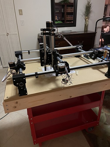
I’m building a MPCNC starting with mostly default settings. I’ve used CNC routers in the past, but never built one. I thought I’d create a thread to log what I learned from it and hopefully it helps someone else and the V1 team with the next version or can improve the online documentation.
For the build process, the documentation has been mostly excellent. The photos were particularly helpful because there were many times I assembled something incorrectly and was able to identify the error with the photos. I found the documentation of the electronics and software parts less straightforward but have gotten a working machine.
The highlights of lessons learned so far:
- I wish all the 3d printed parts had unique numbers (or other identifiers) embedded in them, like they have the C/F/J identifiers, and at times I was craving a corresponding exploded diagram from the CAD . I was able through trial and error to get all the right parts and get the machine assembled, but being able to match the text of the build instructions with uniquely labeled parts would have been helpful.
- Either I overlooked them or the instructions didn’t have a step to cut the belt into the lengths recommended by the calculator as part of the truck assembly and before being asked to thread the belt through the truck.
- Either I overlooked them or the instructions didn’t have a step to cut the lead screw from the default length to the length of EMT conduit used in the Z axis assembly.
- I found the squaring process challenging. I had to revert steps, disassemble the machine, and try again a couple times. After assembly there was interference where you couldn’t get access to the squaring bolt with socket on both sides (or even a regular wrench) and sometimes I was using a socket on 1 side and a pair of needle nose pliers on the other. That worked but put damage and wear on the bolts but worked. I’ll post some pictures and maybe someone can tell me if I overlooked “the better way”.
- I wish the documentation was more clear about whether the 7inch-lb spec was “nice to have” or something critical I should definitely buy a special tool to measure and guarantee. Amazon has something. That force level is smaller than the tools I could find in retail shops could measure - most were for auto use in ft-lbs.
- I ordered a Rambo 1.4 from V1 as part of a dual endstop kit as Rambo seemed the most commonly used / best supported board. The V1 firmware was pre-loaded but not the dual endstop version. It would have been helpful if there was a paper note included with the package telling me which firmware build was factory installed (regular/dual, version#) and that I needed to go get and re-flash it for dual endstop support. I eventually found a forum post that noted the regular firmware M119 reported x, y, z where the dual endstop firmware reported x1, y1, x2, y2, z… Once I understood I needed to change the firmware and later had downloaded and compiled the right firmware I was able to troubleshoot the wiring successfully. With the wrong firmware I had problems like wiring everything same as the photos, but having the software report TRIGGERED endstops when they were open. I also had it activating one not both steppers in the X or Y because I’d wired it according to the dual endstop instructions.
- The endstop wiring was clear to use the - and S pins. I wish the wiring instructions had told me if it was dangerous or harmless if I had the polarity reversed on the endstop wires. There were many references to wiring it for open vs closed without examples of what the connections would like like either way.
- The Rambo photo was not clear whether to use the left or right Z connector when MPCNC has 1 Z stepper. (3rd or 4th from the left) I used the 3rd and that seemed to work.
- It was helpful to find a forum post that it was harmless if the LCD cables were reversed or put on the wrong set of headers and you could use trial and error to get it working.
I did the initial wiring without the LCD connected, so an LCD message regarding which firmware would not have helped me. If there was a G or M code that printed a firmware version/identifier string I could have been asked to enter as part of the instructions to confirm I had the right firmware before proceeding, that would have been helpful.
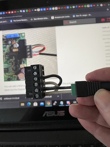
- I couldn’t initially power up the Rambo board correctly because it needed wires that were not included to connect between the green power supply connector jumper block, and the 6-wire jumper block that plugged to the board. Since wires are not included, I wished the documentation included a spec for what gauge of wire to use. ( The web docs did show how to wire the power to both the logic and steppers. Thanks! ) I’m not an EE and it took some internet research to understand what range of wire gauges would be acceptable.
More with pictures later in the thread.


