New to CNCing (with pics) - Where is home?

I have been watching the development of the Lowrider since the first gen was released some years ago. I always told myself that if I purchased a new 3d printer, the first major prints would be Lowrider parts. Well, I got a new printer around the same time as the LR4 was released and dove right in.

I’ve never taken on a project like this and my understanding of mechanical things is extremely limited. But I made it through the build process by following the instructions and my LR4 moves up and down the table using the Jackpot CNC. Time square and then cut some strut plates!

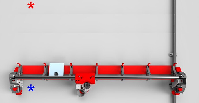
But now I’m confused. I am trying to follow the instructions for “homing” the machine to 0, 0, 0 so I can begin the process of squaring it up. But where is 0,0,0 supposed to be?

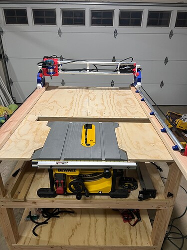
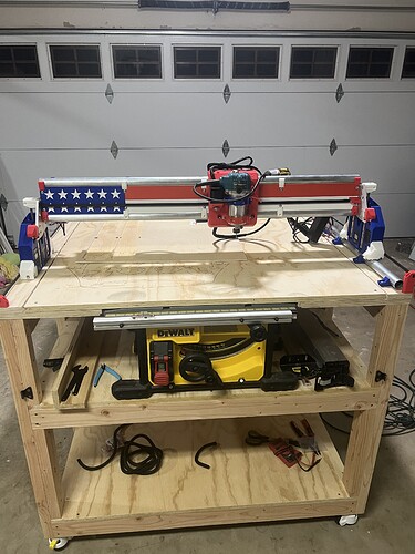
In the above photo, is the home position (0,0,0) supposed to be at the blue asterisk or the red? In other words, is it supposed to be at y-min, x-min, and the highest point on the z-axis? Or is it supposed to be somewhere else? I suppose one of the reason’s I need to know this is so I can confirm that none of my connections to the Jackpot are backwards and everything moves the right way.

Once I figure out where home is supposed to be, do I just manually move the machine to the other 3 extreme corners to make marks and measure for square?

Once the machine is squared, and it send it to its home position, what’s the process for using the touch plate to mark the top of my material so I can start cutting some strut plates?

Sorry for the series of questions. I’m excited to learn, but I think I’m feeling similar to other n00bs on the forum who just don’t know what the next step is.

Appreciate any help!
1 Like

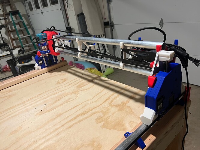
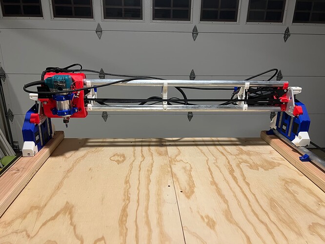
And here are some progress photos. The table consists of three separate workbenches that snap together. It was built this way so I could have some extra wide side-feed tables for the table saw or long out-feed table. When they’re not in use, they come apart and line up along a wall in the garage. I’ll cover them with a good spoil board when using the CNC. We’ll see how it all works.


8 Likes


The Home position is the blue one.
You can check it yourself from the documentation; LowRider CNC V4 - V1 Engineering Documentation
also for probing on the surface of the piece to be cut

A little more complete…

All V1 machines use a “Right hand” set of coordinates. From the point of standing in front of the machine facing it, X min is toward your left hand, and increases as the machine moves towards the right. Y Min is closest to you and increases as the machine moves away. Z min is at the table, and increases as the tool lifts upwards. The name right hand is if you point your right index finger to the right, middle finger forward and thumb straight up, they model the X, Y and Z axes.

Homing the LowRider acually moves towards X=0, Y=0, Z=200. Z homes towards the axis maximum, and you probe towards the table to determine Z=0.

Build looks great! I might be a little bias on the color scheme though! :joy:

Gogo France! :smile::fr:

Pretty neat. Interested in how that turns out in the long run.

You’re really raining on my parade here with that French stuff. Hahahahaha :rofl:

1 Like

Thank you for the clarity. When I first started moving the machine around, homing it was taking me the opposite directions of the end stops. Snd for some reason the name “end stop” was making me think that those must be the “end” of my CNC instead of the beginning (home). Like I said, I’m probably among the least likely of people to be able to DIY thing thing successfully. Appreciate the clear explanation.

Your core looks amazing! How long did that take to print? So cool.

From what I’ve seen, it looks like you’re doing just fine.

1 Like

Basically the same amount of time as a single color. I did it on a Bambu Lab P1S which handled all the color changes. But it only had to change 2x so added maybe 10 min or so. But it was worth it!

Don’t sell yourself short. You can do this and be really good at running your machine. Building it yourself is a tremendous learning experience that will let you understand the machine when you try to use it.

So appreciative of the help so far. Can’t wait to make my first cuts. I’m setting up the gcode for the strut plates (at least I think that’s what I’m doing). I saw in the documentation that 1mm cut depth per pass is a safe place to start. But can I go deeper on the strut plates while using the 3d printed temp-struts?

Well, I cut 3.5mm DOC for my strut plates, but I’m an experienced user, and know what Im looking for. 1-1.5mm for a 1/8" bit is good.

Do some test cuts and measure things first. It’s annoying to waste material on test cuts, but it’s important.

Don’t take for granted that a 1/8" bit will make a cut 1/8" wide. It doesnt always work that way. I use a diameter of 3mm in my CAM setup, or else I get tabs too big, slots too small, and stuff doesn’t fit together. Also, though the GT2 belt is very reliable at 2mm pitch, sometimes it’s out by a bit, if it’s overstretched. I have my movement scale set for the default (100 microsteps/mm at 16× microstepping, on a 16 tooth motor pulley) and it works. Some people report that isn’t right.

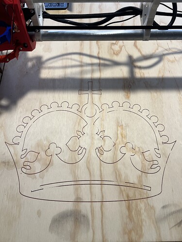
I still suggest that you start with a test crown. Download that gcode file, and run it. It ought to draw a crown, and return to the start position. Once that works, you can go on to making your own code, when you know the machine will follow as designed.

Cut a few squares of different known sizes. I suggest they be sizes you can measure easily with calipers. I use 50, 75 and 100mm. Measure them. Ideally, you get 50, 75, and 100mm, but if not, check the pattern you get.

50.2, 75.2, and 100.2 (same error each time) is probably an error in your bit size definition in CAM.

50.2, 75.3, 100.4 (0.1% error) is more likely to be steps/mm. This might be different jn X than in Y. Try adjusting the belt tension to make these equal, and even better, correct.

You may have a combination of both. If algebra isn’t your thing, we’ll help you work it out. :stuck_out_tongue:

Oh, and measure the squares across the diagonals. This is pretty small, but the 100mm square should have about 141.4 across the diagonals both ways. If not, go back to the docs on squaring the machine.

1 Like

Super helpful. Thank you for the information. I’ll get to work on it.

Should I be cutting strut plates before drawing a crown? I assumed I needed to for rigidity purposes. But perhaps throwing a sharpie across some cardboard is fine with the temp-struts?

No way a pen mount needs more rigidity, and the test crown is a super good idea before trying your own gcode.

Appreciate everyone’s help! I got the crown drawn (more than 1, just for fun) and the strut plates cut. Here are some updated photos.


My strut plates ended up only being 5.3mm thick, so I had some extra room to 3d print some cover plates for the struts.

6 Likes

Ahhhh you beat me to the stars!!! It looks great!

2 Likes

I hit another snag. I was making a cut and a piece of wood snagged between the table and the end mill (I should have used tabs). I quickly shut the machine down, but now when I restart it, the X axis won’t move. Y and Z are working fine, but nothing comes from the X.

I’ve also noticed that one of the bearings on the bottom of the core doesn’t quite touch the gantry rails.

I checked that the belt is still straight and I can move the X axis freely with my hands.
The X axis moves just fine when I twist the nut that connects the toothed pulley to the motor.
The wire connecting the X to the Jackpot is seated fine (and I unplugged and plugged it in several times), but it still won’t move.

What are the next steps for testing that the stepper motor is getting power? What else can I check?