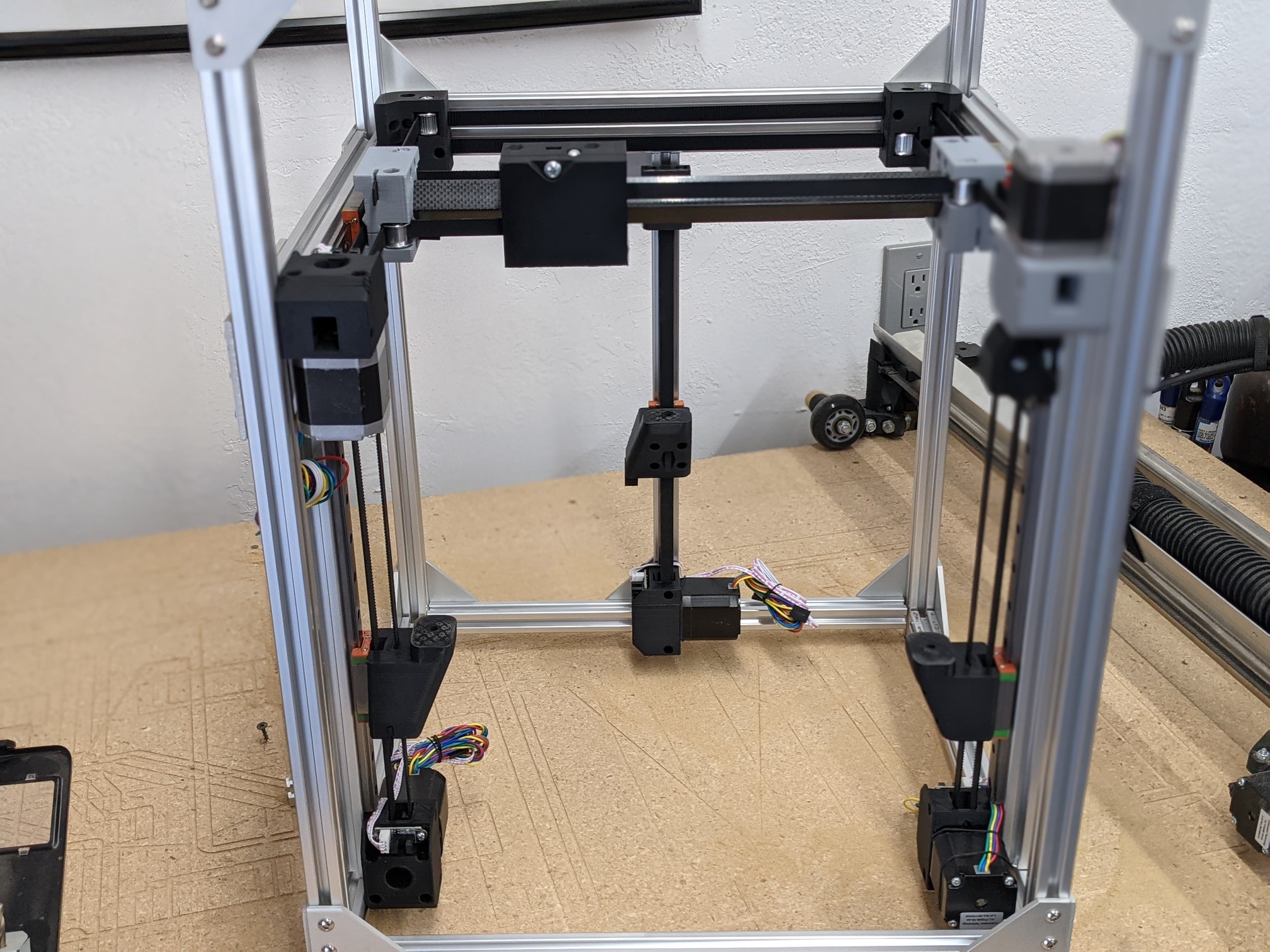
I’m coming from SolidWorks. It was incredibly frustration for a long time. I am proficient at SolidWorks and use hotkeys and things, so any change was going to be tough. There are a lot of things that are not explained anywhere, but they are not for solidworks either. For example, SolidWorks has blue line, fusion has yellow, purple, and orange that mean different things. I am pretty good with Fusion now, weeks later. The last fundamental thing I am not understanding is how the file structure should work for assemblies. I am not really liking building a bunch of parts, and then mating them and making an assembly all in one place. Turns out though you do not have to do it that way, I tried, so this printer is a mismash of assembly styles. The mates in fusion are more complicated than Solidworks for sure…to much clicking through tabs and menus involved.
I have messed with freeCAD for a bit…it was very different and I got nowhere fast. I stopped when I realized things like surfaces and bends might not work as I would use them. If you started there, it probably does everything just fine.
That sounds like my “assemblies”… actually better than my assemblies because mine are just bodies positioned by hand lol! Sounds like you’re getting the hang of them in f360. I need to learn that stuff myself if I want to progress into more complex designs with movement. Like when I look at my primo, I imagine getting those cutouts between the core and trucks right manually would be a pita.
Plus static renderings of an project that has movement are kinda lame… gotta have motion study animations for it to be legit.
I typically do each part in a separate file and then have one assembly file linking all of them.
After last update with the “open file limit” for the free version, I’ve switched to having all the parts as separate objects in the same file. Nice thing here is it’s easier to make a part based off of another one using the face of part A to start part B.
Okay so I did this for the XY, and a separate one for the Z…I then brought in the Z to the XY for a complete assm. How would I take a single component out of the XY and use it somewhere else, just make a copy, what happens to internal references/projections?
I am assembling the last few motion components right now. If it works I can share my file and maybe seeing it done that way might make some sense. The Gist is just have the main/first part selected (the little dot) The instead of sketch use the drop down for new component. Then it starts a new part that you can project or reference surfaces, points, and lines from the other parts. After that you can make a as built joint or a motion joint.
at least that is how I did it, could be very wrong
Two ways I can think of. The most natural is to probably export it. You can then import it to your new project, and also to the old project(removing the original part from the original project) so that if you make any changes to the component it can update in both projects.
If you are satisfied that the part doesn’t need to change, or that is it does it should only change for the new project, no need to reimport it to the old one.
If you don’t want the extra component hanging around and don’t need a single part to update in multiple projects, try insert → derive. Then you can choose the project, which will open, and select the parts you want (i think from the tree is easiest, especially for components with a lot of bodies).
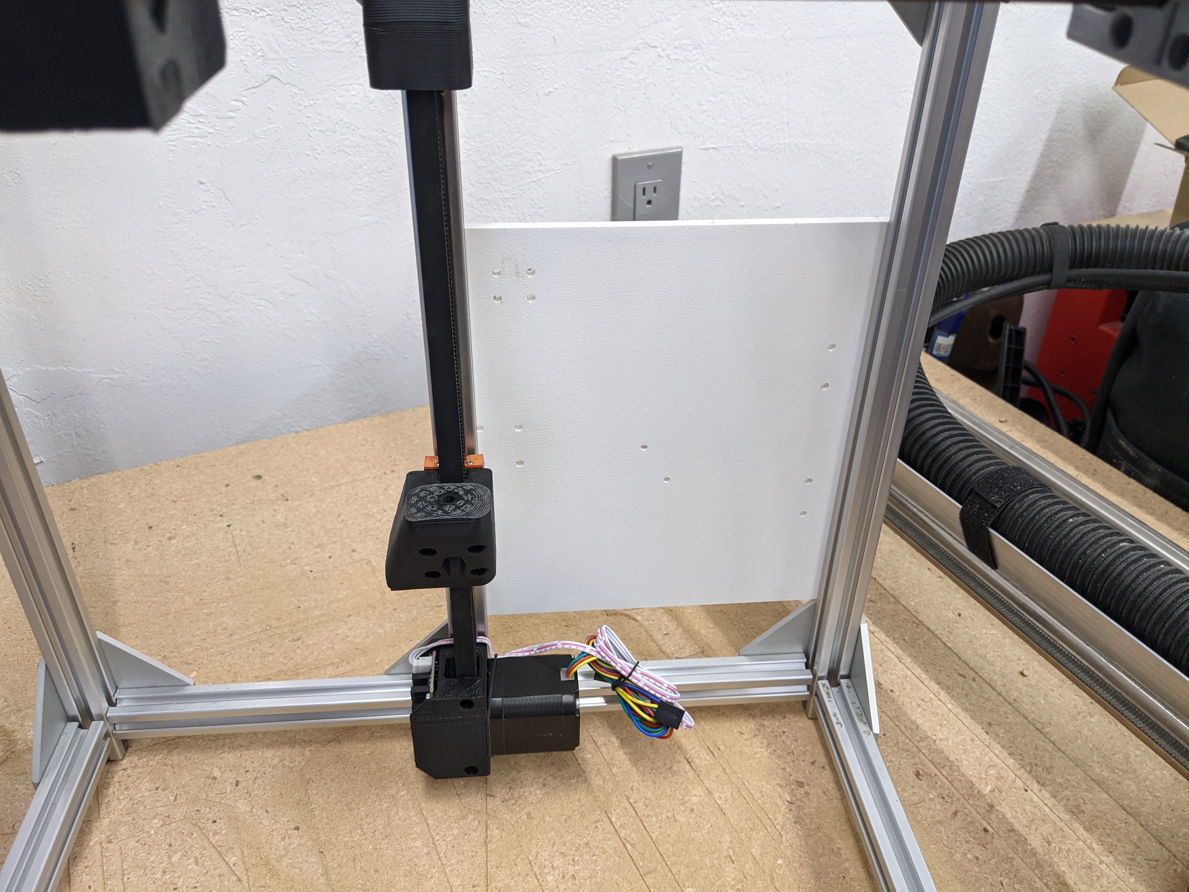
Time to cut out the bed plate and maybe wire up the motion system. I had plans to also make an extrusion based bed plate as well but I am dying to drive this thing already.
6 motor drivers… Hmmm. I might end up using the SKR Pro for this instead of the LR2. Well, I have another Duet Wifi, which I know can handle the LR2, since I have one handling the Primo just fine.
So…am I a bonehead? Well, yes, but let me be more specific. I can’t seem to home Z to min or max with multiple Z drivers. Everything seems to be in place, but it fails. I can get it to compile with the BL touch with leveling and all that.
I kinda thought it would home to Z max…then bed probe and level. I can only get it to compile if I only do probing and leveling. I can’t get it to just home to regular Z min or max max. Odd, or am I a Bonehead.
I am fine with the BL Touch, I just wanted to test it out without setting all that up. I mean, cool, it saves a few dollars in endstops and running extra wires. Just feels odd regular homing doesn’t work.
When I saw the sensors, I’d assumed that you were going for a level bed at a known Z. Of course so far, you didn’t have a BL Touch in any of the pictures.
I know that I could do it with RepRapFirmware, but that’s not really helpful with Marlin. Maybe that’s a reason why so many of those printers use Duet hardware. It’s a bit of a jump, but I did find (And am giving consideration to) A RepRap Firmware port for the SKR Pro because ultimately, it’s a firmware that I’m more familiar with.
I know that I could do it with that firmware because homing is done explicitly with Gcode, and need not use the same probe(G30) command that would be used for the BL Touch. I can simply list 3 switches for Z Max, and 3 drives, and tell it to go down until it triggered them.
It does seem to me that if I can configure RepRap Firmware to do it, it should be possible to do the same with Marlin, but… I have no idea how.
If you just configure three Z motors and endstops, I would think that works. If you do the probe, I think that replaces everything. We had to get the right set of partake to slow probing and endstops in the lr config.
I would stick with the bltouch. Make sure it can adjust the Z after probing the the corners. Then, if you still have the itch, remove the bltouch config and try the triple homing.
None of my bltouch printers have z endstops anymore.
The reason I was hoping to do both would have been power loss recovery. I was hoping Home Z, probe, the offsets would get stored for that print, if the power dumped it could home Z and just reuse the map since the BL can not be used with a print on the bed.
I poked around a little longer. I am 51% sure it is a Marlin bug. I figure anyone doing the 3 Z steppers are using a BL so it probably has never been tested without. Is says it is missing declarations for Z2 and Z3. The silver lining is less wires and smaller parts without the Z triggers.