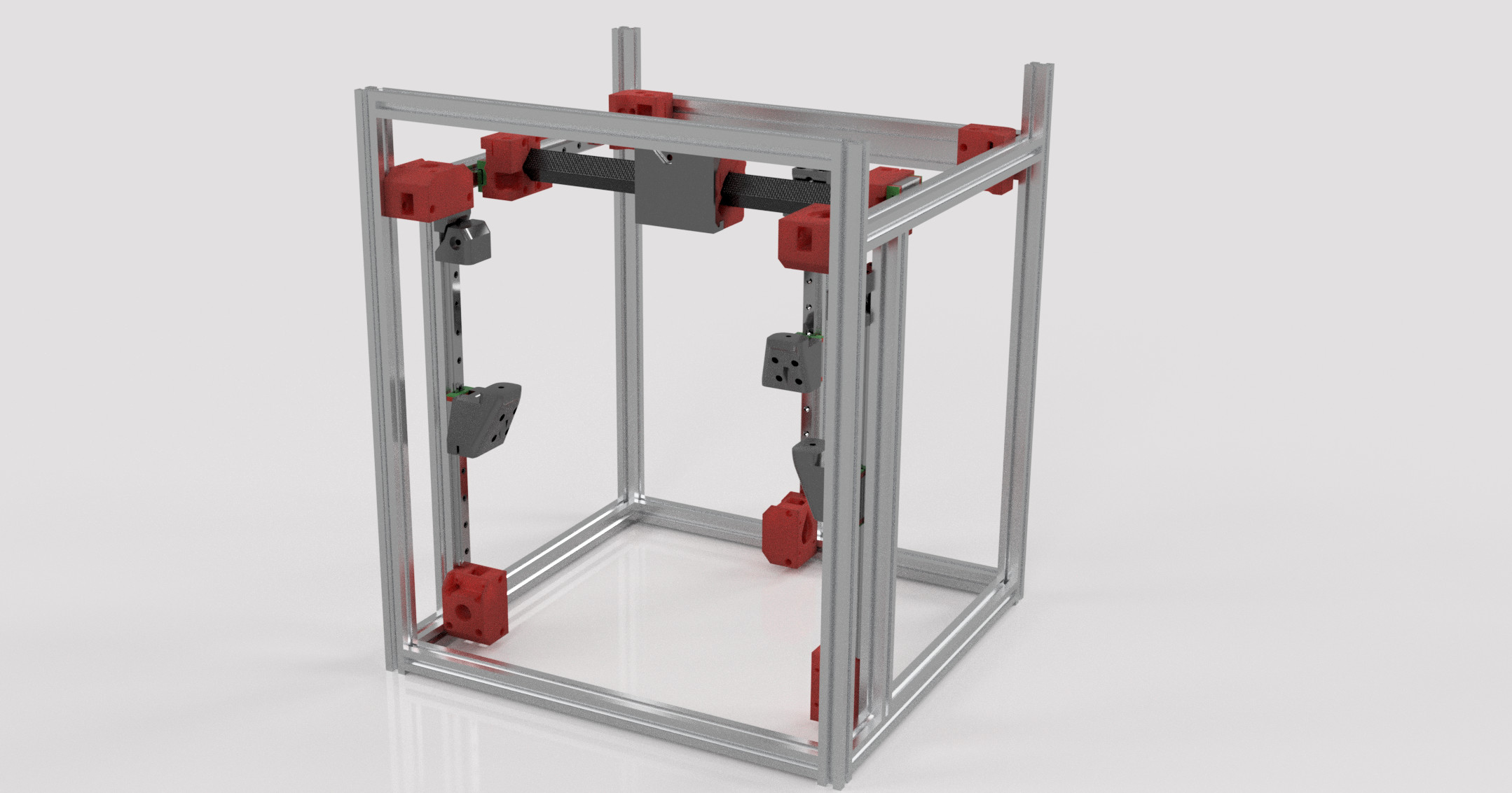
20mmx20mm, Bed width plus 150mm or so.
I cranked down on it with a test piece and the wheels will crack it. I heard it but do not see an actual crack so extremely minimal tension. I am wondering about longevity.
20mmx20mm, Bed width plus 150mm or so.
I cranked down on it with a test piece and the wheels will crack it. I heard it but do not see an actual crack so extremely minimal tension. I am wondering about longevity.
Small update, I think I worked out all the stuff. Printing the Z tensioner, if it works out I will finalize the Z bed mounts and give it a shot pretty soon.
Ouch… cracking cf is not good. If the wheels rest in the middle of the flat, that will maximize strain, vs being closer to the corners of the extrusion. It is hard to tell where the wheels are tracking from the pics. Otherwise, maybe adding more wheels to spread the load better (dually style)?
I might opt for 20mm thin wall aluminum tube. 1/16" wall tube is also super light, and might be a little more durable, though it’s definitely also crushable.
Do you think that there would be adjustment room for 3/4"? That’s available locally.
That’s also what I’m likely to make the frame out of instead of 2020, and have it reinforced with 1/4" plywood.
The wheels can be moved closer to an edge, I was messing with that, but I don’t think it is really needed. I am hoping the tiny bit of give in the center will keep it smoother by flexing a bit under any CF deviations.
I cracked it on purpose. I cranked down on the clamp to see what would happen. You can tell far before it cracks you are too tight.
Aluminum would be fine for the cross bar. 3/4 would take significant adjustments on the “hub” part and the truck part. In the end I am sure it would be fine. The CAD model will be available so you can edit it all you want.
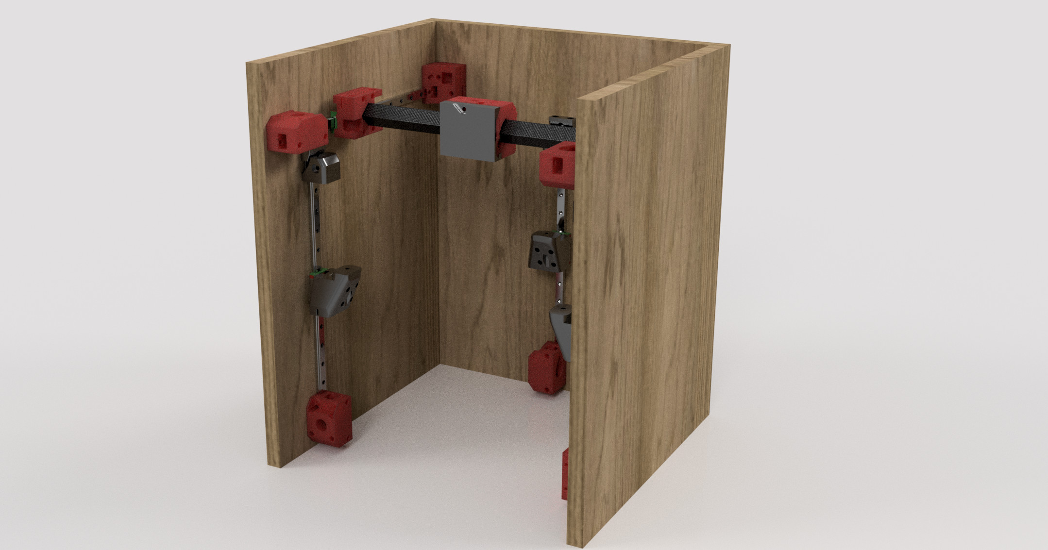
As for using tube for the frame…if you are not using 2020 you might as well just use flat panels and skip the squares. That is the purpose for making it all single surface referenced. I am only using the 2020 because I am changing sizes daily on a lot of the parts. I will cut it out of wood or plastic again soon.
I have never really tested this. Any idea how far I can undercut? This piece is undercut 20mm, the part still on the bed would be 30x35.
I would think the angle would matter, but the undercut distance wouldn’t until it had enough of a lever arm to pop it off the bed.
That is what I figured. I made the angle very slight, and the bump at the top is just barely over the tipping point. It prints fine, but I wasn’t sure if there was a rule of thumb for undercuts, like the 45 degree rule for overhangs.
That part is the primitive shape for the bed support for the Z linear rail. It will allow for nearly a 20 degree tilt in any direction. I know that is over kill but I had to try it. I looked at a bunch of other printers and I really hope my simple approach works as I intend. I have everything to print and put together a build tomorrow. I have a extruder/bltouch/fan mount sketched out so that should be quick.
Getting excited. A lot of the parts are still primitive and need some flavor, the build is not fully parametric, but for now I think I have a full proof of concept. I learned a ton of Fusion so I probably need to give everything a once over if it works. I know my model is really bad in the beginning, as I learned a ton later in the process. Still not confident in the assembly side of things and how parts and files should be handled, but it works.
I will work on the rest of the CAD full assembly and the real build at the same time, hopefully tomorrow.
I’m definitely not the expert 
Looks like a fun print though.
Well since you mention it, the print is pretty interesting. To get that nice smooth top I used variable layer heights. Thick on the bottom and at the dome, I went really thin to get that smooth transition. Not that it is needed more to make it a more interesting print.
I actually woke up thinking about it several times last night. 20 degrees is probably asking a lot. I am going to take that down a lot. If I am doing the trig right, a 5 degree tilt on the bed would put the mount 34mm out of plane (and only require the slot for the bed plate to be 1.4mm longer in one direction).
That is ridiculous. 2 degrees gives you ~14mm of correction. Shoot I should have done this math first…lazy engineer.
Okay so maybe we do it this way. If we were to ever use non planar printing, how far would we need to go? Our current nozzle do not let us go more than a few degrees of plane. Fancy nozzle allow for more. Google here I come.
Yea, that’s going to depend on the hotend.
Well, that is cool. It makes it a lot easier. Trying to do the Fusion Assembly now.
What about the V wheels that ride on the corners instead of the flats?
I didn’t have any of those on hand. I was also concerned about how true the edge would be, thinking back, it is probably the truest part, but it is pretty round. Hmmmm, it is a good idea, then you would be banking on the wheel bearings and then fitting sung in the parts. I am not sure but I think the way I have it is the easiest way to have sloppy fits and parts and still get accurate motion. Point load vs a larger contact patch?
I am going to be thinking about that, though. You might be right.
So many angles this can be looked at. On the CF centric view, corner wheels would take almost all lateral loads off the wall, thus drastically improving buckling performance. OTOH the wheels are no less important to hold that line. I suspect just the deflection near the middle alone might make the adjacent wheels lift/smash their surfaces for certain loads. I think contact patch only matters wrt load spread (not traction) but not sure which geometry wins that race here.
Bottom line though, is deflection in operation. Engineering is sometimes more testing than calculating, and you already have something nearly ready to test. I am looking forward to seeing the results as all the ideas you are considering are uncharted anyways👍.
You either have a really clean shop, or you need to make that for real!
That is certainly the most fun way!
I keep rebuilding, editing, reprinting. I am hesitant to cut the last few pieces of Extrusion, I cut three pieces 5mm too short so I want to be sure I have it dimensionally correct before I chop any more pieces. Since I am new to the Fusion side of things, I made a few rookie mistakes and I am catching them during the build.
I really like the way the wood render looks, seems so simple an clean. I was going to cut fancy cutouts and stuff into it, but I find the simplicity oddly satisfying.
In many ways too… being a printer it already has half a heated enclosure integrated right into the frame. Trussing the panels put would kill that benefit. Heck, maybe even use radiant barrier Osb for the sides just in case it ends up with an enclosure hehe… they do help a ton with winter prints, abs, and nylon.
So, how are you liking the overall experience so far? I was pretty impressed with how efficient the workflow was coming from free cad… at least after the first few weeks of learning where everything is.