How about those heatsinks on the esp32, could there be a gpio short? Or even on the stepper drivers.
Pins 1 and 4 on the 6-pin connector is not correct, based on the image of how your wires are set up.
The jackpot board (and every 3D printer board I have ever seen) expects adjacent wires to be connected to a coil, like this:

What you have described, the first and 4th pin left-to-right and also 1st and 4th pin right to left, is this:
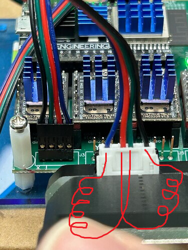
That will make the motors not turn.
Ok major new development.
So the questions about which stepper motors caused some thought.
It’s true that I have used only standard pinned motors without deviation from that to remove as many variables as possible so my thought was ok so why not try some oddball steppers just to see what happens.
So one of them was a mini Nema 11 attached to a small peristaltic pump.
It works! Why? Dunno??? It’s actually pinned the same now that I put my meter on it.
However I did notice it move slower than expected even at 5000 or even 7000mm/min which is faster than I’ve ever tried any stepper before. But it is a tiny little thing.
Is it possible somehow that my driver are running low voltage? It would have to be seriously low to not move a little Nema 17.
I only ask first before trying to adjust the drivers because a. I don’t know how (yeah I’ll google it lol no big deal) 2: I’d rather not mess with them if you guys seem to think they are generally set correct from factory and III. Does it make any sense at all that I would get the only five 2209s all set to the same low voltage from the factory?
Really wish I could post a video on here
YouTube links are converted to embedded videos, if that helps. No special syntax, just drop the link in the text of the post.
The TMC 2209 drivers have strength (drive current) controlled by software, so they can’t be adjusted high or low from the factory. With the standard setup the Jackpot drives them with 1 amp when turning.
Yeah I’m a new user so the ability to post links isn’t available to me.
@Bret_Martineau asked me to post this video. He sent the following comment with it:
Ok this better than nothing but I’m not sure for what

Bret, did you catch what @jamiek said about the stepper wiring order?
1 Like
Just to restate things, troubleshooting, with measurments, in a table, to answer Jamie’s spot-on request:
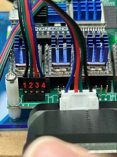
1, 2 need to be a coil (and low resistance), and 3,4 need to be a coil, and low resistance.
Anything besides that, it isn’t standard stepper wiring.
We see wrong cables all the time from suppliers, so it’s very possible.
1 Like
So I read through this whole thead but didn’t see anything about setting the current on the drivers. They all have adjustment pots on them, and you said they are “normal”, which to me means standalone which requires manual current adjustment. Check and adjust with a meter because they usually come set randomly, at least in my personal experience. Thats my guess on this.
FluidNC programs the current settings into the TMC2209s using the settings in the config file. You DON’T want to monkey with manual settings.
3 Likes
Ok I have wired the none working steppers up every way imaginable based on diagrams, meter readings, suggestions from the forum and everything in between.
I have done that with the new ymal file, the old file, the original file and a gethub file.
I have taken each component out and tried them on known to work boards of every variety
From grbl 3 axis, grbl 4 axis, mach3, mach4, and even an RPI Pico that runs a short program through a DM542 driver. Each component works as intended when not hooked to the FluidNc board.
No…. No no… I am not blaming the board. The board is awesome. Everything about it is perfect for what I’m doing from the interface to the multiple gpio options.
What I’m saying is I’ve tried everything I can think of accept changing the voltage and current settings. Is everyone opposed to that?
Except writing down and reporting in a clear way the requested data.
What, exactly, were the resistance measurements of the 6 requested pin test combinations?
Under no load, if you can’t move the steppers with the default settings, something is miswired.
Jackpots are also tested, are known to work.
You can crank the settings up as high as you want, right up till you burn up a driver.
It’s your hardware. Have at it.
Noted.
At this point, I’d say you have stellar success with your other available board solutions, and you’re wasting your time with a board that you can’t make work.
Community support here can’t help you, because you steadfastly refuse to supply the data necessary to do troubleshooting.
You haven’t yet even made it run well enough to pull the endstop shorting jumpers out to try and make the proximity sensors work, and that will be your next hurdle along with adapting to the FluidNC rotary axis g code behavior.
All that’s a real bummer, but my advice to you is to use what you can make work.
What model is your “grbl 3 axis” board? Does it have a name that we can look up separately? I am guessing it is wired differently (coils connected to non-adjacent pins) and that is why it works.
Without a model number for one of the working boards, or a model number for the motor, there is no way for to know.
Incidentally there is no standard wiring of motors. Wire colors and pin ordering can be different depending where you bought them or what equipment they came with.
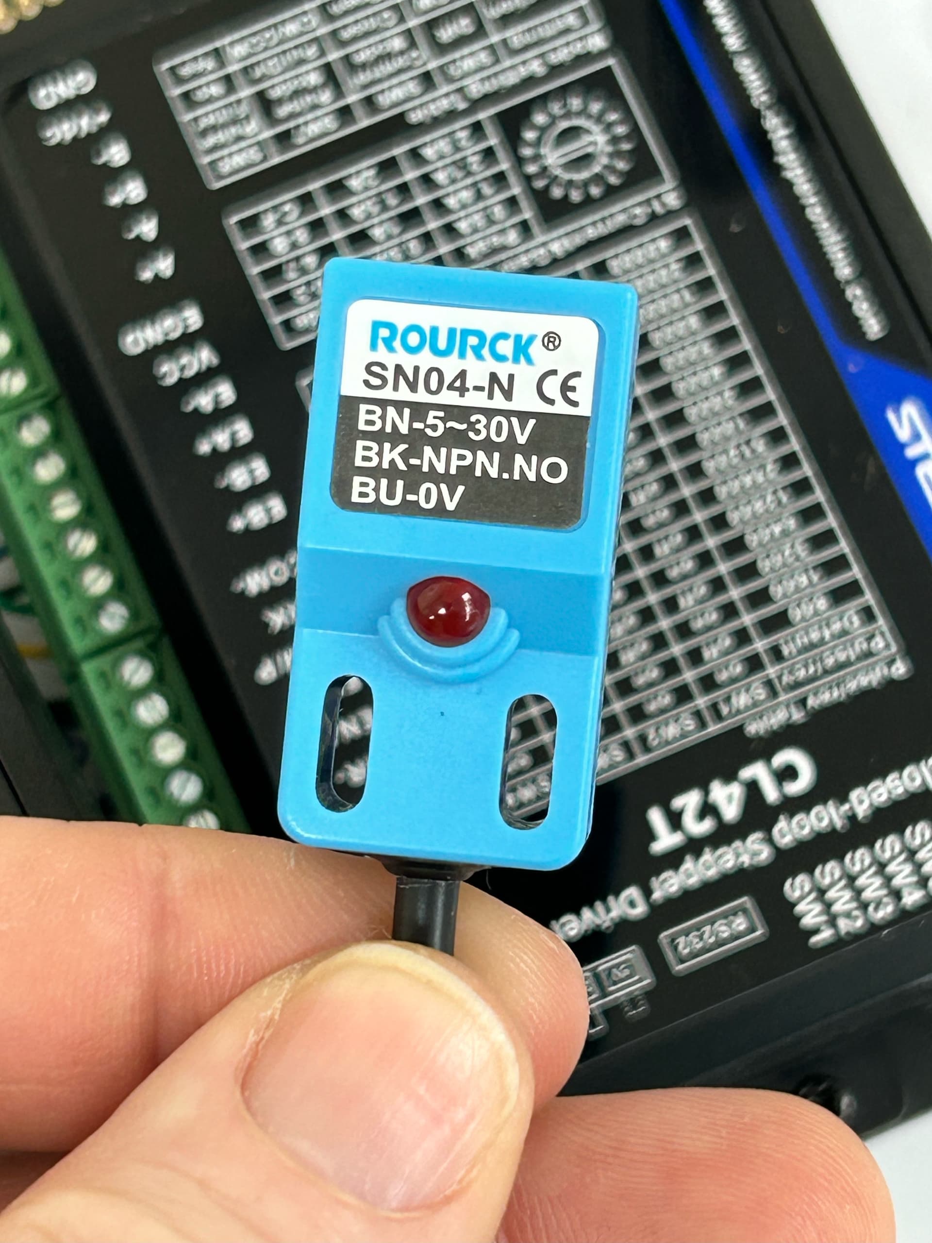
I’ll make your day, Jim. Behold the proximity switch part number is now before you kind sir.
ROURCK ®
SNO4-N CE
BN-5-30V
BK-NPN.NO
BU-OV
And one more time for my peeps in the back ![]()
![]()
![]()
If you are wondering why I’m not posting the following: links, pictures, YouTube videos or files of any kind, even the kind of files that would be super duper helpful.
I’ll say it again
**** I can’t… because I am a new member.**** Doug… the very awesome Doug has been kind enough to let me send things to him so he can post them for me.
Altered Ymal posted ![]()
Switched to original Ymal ![]()
$SS posted ![]()
Step wires ohm’d & pinned as Jamie said ![]()
Power supply 24v ![]()
Drivers new unaltered ![]()
Board checked at factory before delivery ![]()
Tested all steppers with known to work boards ![]()
What’s left to check. That’s not a rhetorical question. The driver voltage and current is just an idea. Asking the group what they think.
Jamie wants to go further with the stepper wiring. I’m all for it. I spent hours on the wiring pin out today but I need this to work so I’m down for it for.
So far I’ve sent all the requests accept the ones I just got from you about the resistance readings late tonight and the known to work boards request from Jamie.
What other requests am I missing.
Again if it’s a file, pic or video etc check Doug’s posts first because he’s been kind enough to post the them as I send them to him.
I don’t have the resistance readings as the request was a couple hours after I finished with the stepper pin out.
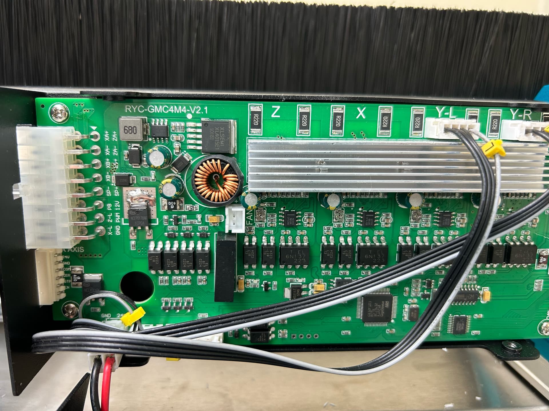
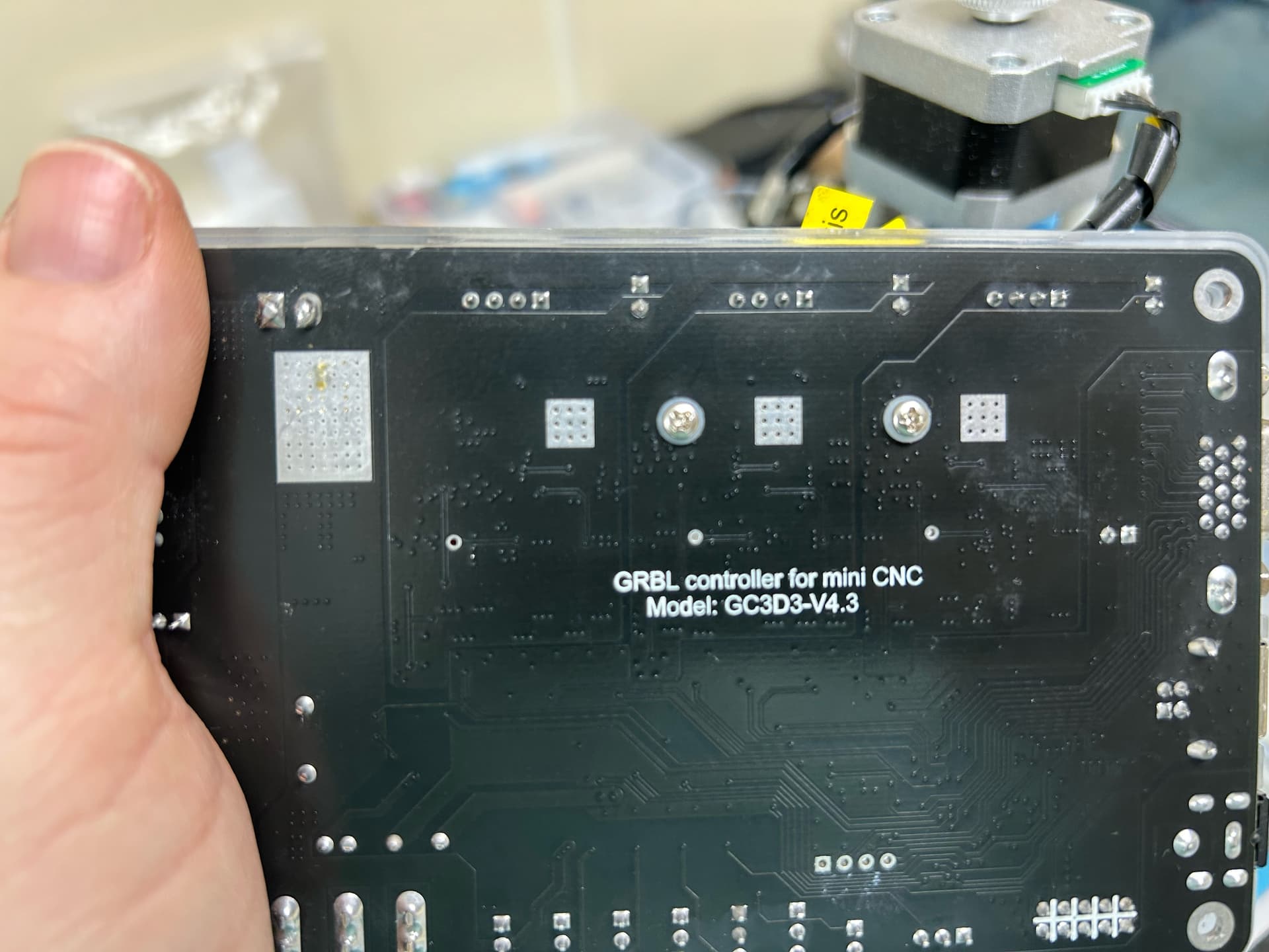
Here’s the Grbl board info for Jamie
Grbl GC3D3-V4.3
Grbl RYC-GMC4M4-V2.1
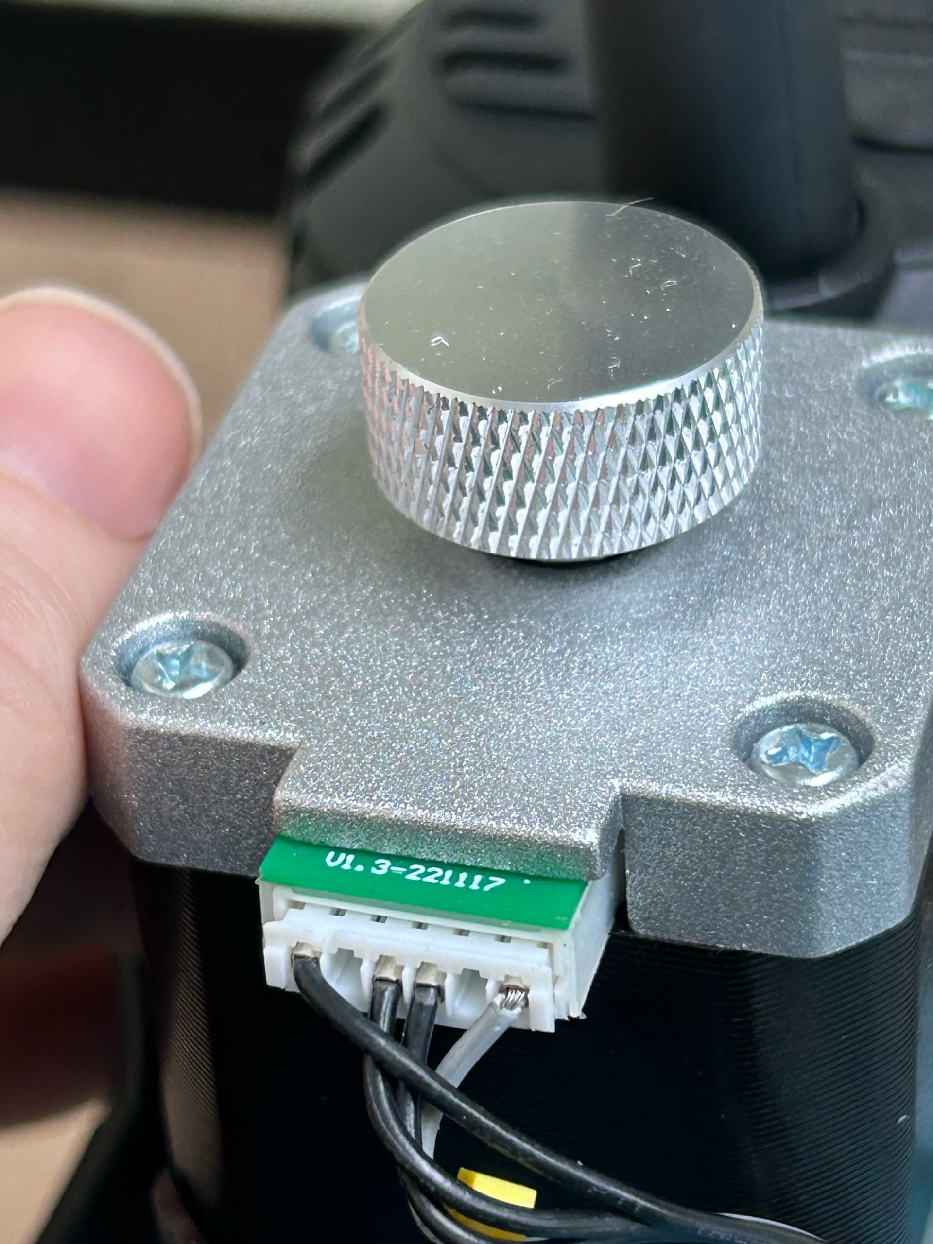
And I have several of the same stepper that works on these boards that I would like to use. The only number on them is as follows: V01.3-221117
That number is on the chip board that protrudes from the side and it’s the only number on them. It’s probably not a part number for the motor but it’s all that’s there.
The Nema 11 that works on both Grbl boards as well as the FluidNc board is
Kamoer
KPHM100-STB10
С4Е2624092
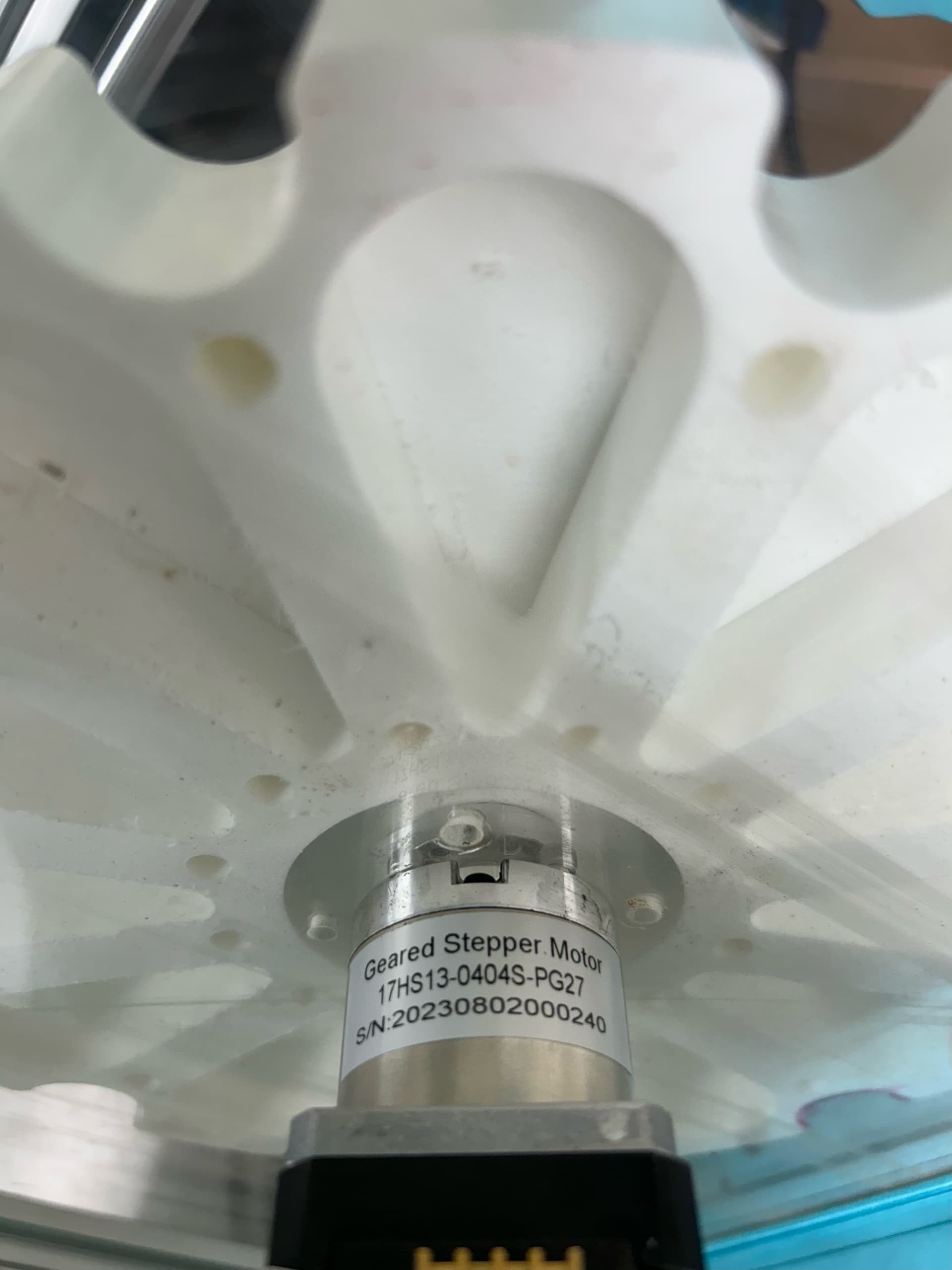
The only Nema 17 that works on the two Grbl boards and also the FluidNc board is from Stepper online.
Geared Stepper Motor
17HS13-0404S-PG27
SIN:20230802000240
Please note that I didn’t just pop a question on here and dip. I’m working on this and reporting back what I can and taking all feedback.
Thanks a million to the forum members that are taking time to pitch in.
.
1 Like
Reading back through I don’t think I see it anywhere: HOW are you testing the movement of the steppers?
Please confirm you are testing each time using the fluidNC user interface in a browser - it looks like this
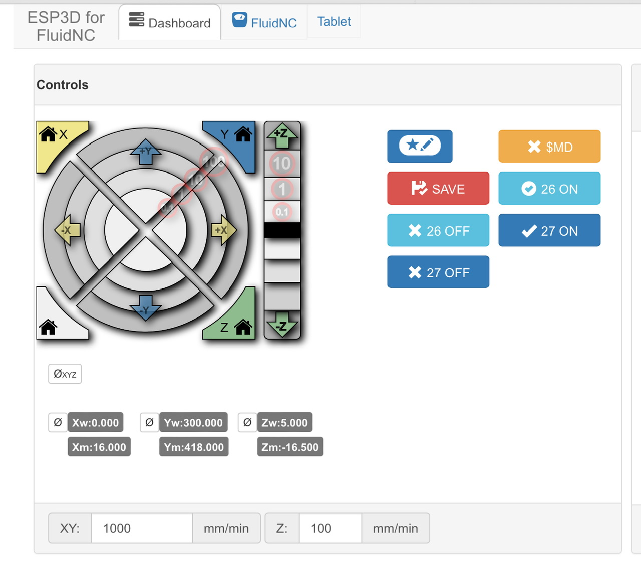
Just trying to eliminate assumptions and variables.
Here’s the latest batch of photos emailed by @Bret_Martineau since he cannot post them due to new account.
The note he added at the top reads:
I went back to the original Ymal file earlier today just to eliminate any unforeseen problems.
One of the guys from the forum (Jamie?) was asking for the info on the known to work Grbl boards.I sent the part numbers but here’s pics of the stamp.


Question: So your drivers and board work fine (lets just ignore the endstops/limit switches for the sake of clarity) with the standard nema steppers, but when you swap to these steppers that you want to use in production it doesn’t work? Is that the one in the video making the bad noise and jumping around? The fault is caused by switching to these alternative motors?
As well as the measurements @jamiek has requested, perhaps some more information about what these are, where they are from and under what circumstances they work on the other boards (those other boards you mentioned don’t seem to be anything special or unusual). It looks like there is some sort of mechanism/gearing on the shaft, could this be slipping if you are attempting to turn too fast? I wonder if you test with a lower feed rate and acceleration? How are you testing to produce the error?
Fluidnc sets this on the driver in the config file. You can up it in there if you want to use more current to drive the motor. The config you have run_amps: 0.800000 should be enough to turn an unloaded stepper motor though.
Maybe just post some video’s and photos of your setup🤣
Yeah I’m using the interface in your picture. With an ohm meter to find the pairs.
Looking at the spec for that:
Electrical Specification
- Manufacturer Part Number: 17HS13-0404S-PG27
- Motor Type: Bipolar Stepper
- Step Angle: 0.067deg
- Holding Torque without Gearbox: 25Ncm(31.2oz.in)
- Rated Current/phase: 0.4A
- Phase Resistance: 27ohms
- Inductance: 28.5mH ± 20%(1KHz)
- Insulation Class: B 130°C[266°F]
Its only rated for 0.4A and you are running it twice that. Or perhaps I’m misinterpreting the documentation.
Edit Maybe change the amps (running hold and home current) down to like 0.2?