Aren’t most of the steppers we use 1.8 degrees or 0.9? Could it be the steps per mm is wrong?
2 Likes
Rob I see you’ve got jokes ![]()
![]()
![]()
![]()
It’s been a long day haha I needed a laugh.
As you were posting I think Doug posted the pics of the boards I’ve used these steppers successfully on. You are correct. They are nothing special. Just Sainsmart Genmitsu Grbl boards. The step motor that I want to use with the knob on top is a Sainsmart Genmitsu as well so nothing special there. They have a little more torque than a small Nema 17 but not much.
The way I’ve been testing is just finding the pairs with ohm meter, using Jamie’s suggestion for pin out given what the meter says and then I plug in the fluid board, connect to fluid WiFi allow the board to spin up and then I always have motor I know works in one axis so I test that the board functions then I try the stepper that has been repinned.
Your suggestion of taking note of the speed is an excellent idea and makes total sense. Because yes they are acting like a stepper that is loosing steps but with no resistance. The program does have 2000mm/min in when it boots up and yeah that crazy high for a test now that you mention it. I’ll change that to 500 or even 250.
I think you are correct! I’ll have to check the file as I’m not as familiar with it as you guys. That’s an excellent question. Yes I’ll definitely check that when I get to the shop.
Whatever axis that stepper is on, I think you should try bring this down to a safer value. Like 0.200000 perhaps. If it won’t turn, you can up it but those steppers seem to be rated to 0.4.
1 Like
I can’t find a spec for the pump stepper. But I’m sure its a lower power application that driving a cnc axis, unless you are pumping mercury or something. Maybe experiment with much lower current settings on the pump stepper too and monitor the temperature.
Edit
24v at 10w ~ 0.4A
So defo try a lower current setting on the pump too.
1 Like
The pump stepper is going to be pumping low viscosity liquid but I’ll definitely keep an eye on the temp. I’m hoping it gets plenty of down time for cooling between pumping cycles.
It will be 10ml each cycle (16 revolutions) and one step in reverse (no drip) then approximately 12 seconds of rest.
Do you know how to edit the fluidnc config? You can do it in the GUI or by copying a new file over. You have to be careful how you save or you can overwrite your newly updated config with the running config in memory.
I’ll lower the current on the pump too. Good catch.
I can edit the config but I’m very reluctant to do much to it. The guys on here seem to have a healthy fear of that config file and I’m in no position to test those waters ![]()
1 Like
Your limit on posting images and links is brief. It doesn’t take much poking around to get the permission.
This will be the gearbox. This model has a 27:1 planetary gear ratio. Then 1.8/27 = 0.06666.
Everything else that I’m seeing seems ok so far…
One more thing, just a note that a stepper motor will consume current and heat up even when it’s not rotating. Something to keep in mind.
What power supply voltage are you using? 12V?
it’s
Yes, that’s the key troubleshooting data. From one or more of the steppers that isn’t working, gather this data and report.
Back to Jamie’s original request:
This is asking for a table of results, where you list the results in measured units at the connector on the jackpot.
Resistance measurement, pin 1 to 2: ____________
Resistance measurement, pin 3 to 4: ____________
Resistance measurement, pin 1 to 3: ____________
Resistance measurement, pin 1 to 4: ____________
Resistance measurement, pin 2 to 3: ____________
Resistance measurement, pin 2 to 4: ____________
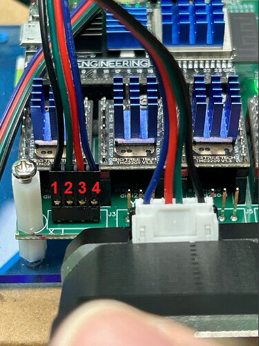
Why so much focus on wiring? Because it isn’t clear you’ve got it correct, and from the evidence it appears that some connections are questionable.
Note the setup below doesn’t have the correct connector plugged into the stepper, and if you have an open on either coil or a miswire this won’t work; exactly as you’re reporting.
I’d recommend making the resistance measurements and doing motion tests using the correct white connector in the stepper motor rather than the test leads pictured bove.
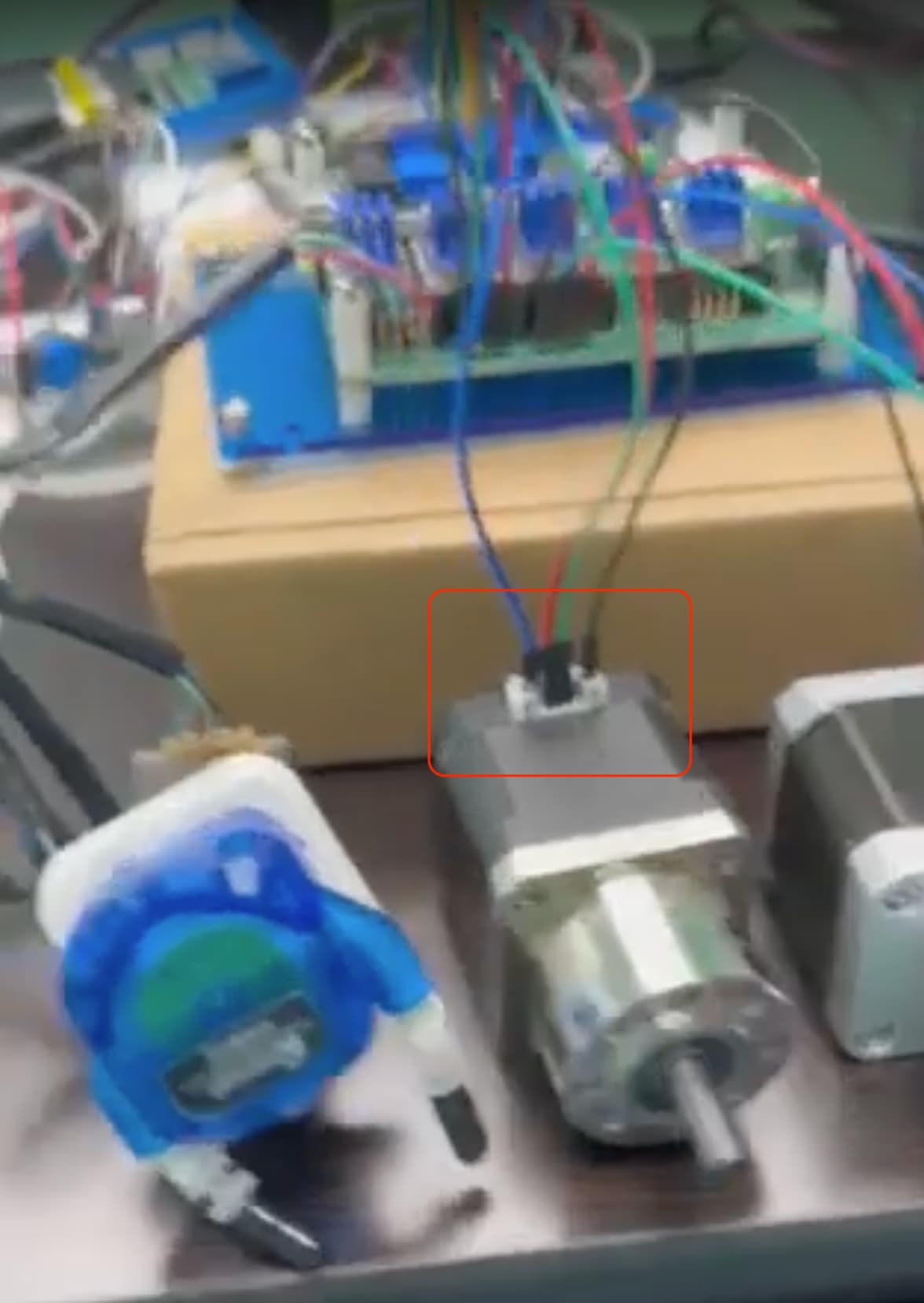
Honestly I have kept back from posting, but this is what the videos I saw portray. The steppers are fighting each other, but that said, I am stepping back out. I hope you get this resolved.
2 Likes
@Bret_Martineau - you can quickly earn Trust Level 1 by simply visiting some other threads and doing some reading of those threads , or posting in some relevant threads ( no spam posts please).
The threshold for various trust levels is here
1 Like
Just skimming this as others are on things more in depth. However I picked up an new extruder/stepper set for my printer and it was running backwards in relation to the code. Looking at all the instructions I could find to reverse a stepper by wiring ended up with 2 coils in opposition of each other (thanks youtube! You’re NEEEEEVER (we need a sarcasm font) wrong!) and it was very unhappy and made similar noises to the video. Swapping the wires correctly and it’s in business.
Just thinking out loud (actually typing in silence…)
Seeing mention of the end stops, they don’t matter. The board only pays attention to them during homing.
If we do basic troubleshooting flow, start with where you know it’s right and work to where it’s wrong…
You’ve connected the motors to other boards and they worked so motors are good. Your computer is apparently talking to the board, and it appears to be feeding the code, so that’s good.
The board appears to be talking to the steppers, they’re at least powering up, so that’s good. I’m assuming when powered up they’re locked so you can’t turn them by hand.
That leaves us in the middle with either all the drivers being bad, or just the wiring being bad. If all the wires were made at the same place, it would not be unreasonable to assume that if 1 has an error in order, they all share the same error.
Since every driver is independent of the others, there would have to be multiple identical failures. Not impossible but not super likely either.
It could be completely perfect hardware, which would push towards a software/programming issue. But if you’re using bone stock in that regard, it shouldn’t be an issue.
If you had an identical board the easy test then is to just swap the boards and do a wire for wire move and see if the problem persists (not the board) or is cured (is the board). But if you have other boards which are apparently working with you setup, why not just change boards to complete the project and worry about the jackpot on another day?
Nathan I agree with what you are saying yes you are correct in your assumption that the motors lock up when wired one way and do what is seen in the video if wired the other way.
The reason for being persistent with the jackpot board is I will not be around when this machine is used and I need it to be simple for an employee to operate. Mach3 is just not. And it allows the end user full access to the inner workings of the machine with no special permissions or procedures needed to change any of it. FluidNc also allows certain changes from the web interface but at least those menus have clues that you shouldn’t do that. As in “oh I see a big red garbage can emoji next to this file labeled config so maybe I shouldn’t click that” ![]()
In short I need an interface that is as close to an on/off switch as possible. FluidNc offers that. Turn it on, press home, pick the program and send it. It won’t take hours of training them to be able to do that.
I ended up having to fly back to Florida yesterday so I won’t be able to do any further testing for a few days.
2 Likes
Where in Florida? I’m up by the cape.
So can you buy just one stepper Motor and test please? It would be very helpful to know if this is your stepper motors or not. You can test by moving through all the stepper drivers.