Yes I have them all the way down now.
There is a new Z Endstop model with longer slots if you have a printer. They have been shipping with the kits for a long while now.
If not just bend the metal arms down a bit. Little bend in the middle not the whole arm.
1 Like
I bought some of those barrel connection plugs in the CCTV section of Microcenter in Minneapolis and proceeded to tighten them sufficiently. Turned out they stripped out and didn’t end up holding the wire at all. I ended up tossing them and soldering the wire to a rocker switch and adding another small section with a crimped connector on the end to connect to the board. I hope yours turn out better than mine did.
1 Like
Mine did. After I stripped the wire I carefully and smoothly tinned it with solder to create a solid wire. I think with those small screw type connectors the spread out a small gauge stranded wire around the locking screw, and end up bottoming out which causes them to strip or actually over run their threads. That also would allow the wire to pull out because it is not under the screw. This probably ties into the “many problems associated with them” that Ryan mentioned above in my post.
But hey you found a work around and moved forward. Great job!!
2 Likes
Thanks Ryan where can I find the new print file? I do have a printer and it is raring to go.
1 Like
A potentially better approach would be to use a crimp ferrule on the stranded wire ends before inserting them. One big reason that stranded wire works lose is the strand bundle eventually compresses under screw clamp force and then can work out. The crimp ferrule fully compresses the stranded wire bundle and eliminates that failure mode. Solder cracks, and most people are actually really crappy at soldering. Also, solder on stranded wire where there is motion tends to break wire strands at the solder/stranded interfaces.
But the biggest problem with those CCTV style connectors in my opinion isn’t the screw clamps, it is that there isn’t positive retention of the barrel/jack portion and those have proved relatively easy to pull apart. Not so much in a CCTV installation where they see little motion but very much so in a machine that moves and creates plenty of vibration.
3 Likes
It is in the printable LR3 page.
Yup, and the outer jacket is just a crimp ring that is usually not tight enough. I have a few hundred that I have not had the heart to throw away…maybe an ebay deal soon.
1 Like
TOTALLY agree but a couple of things, 1. I could not think of the technical term for them so I didn’t want to mention them. 2. I am out and didn’t want to go to the store again. Wanted to keep moving forward and soldering I am experienced with. I have ordered more and when they come in I will "probably’ rework the connections. 3. I am going to configure some sort of strain relief at the outside of the case to protect from being able to disconnect unless needed to.
2 Likes
Printing now!! Just an FYI (and it may just be me) I did not see them in the thingiverse link but they are there in the pintables link.
1 Like
WELL let the problems commence… Please help…
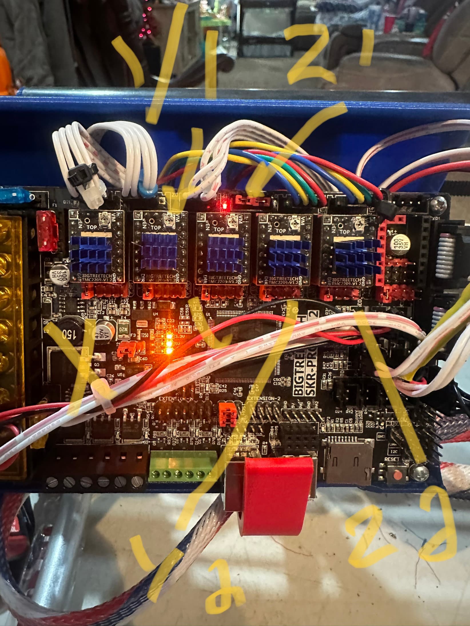
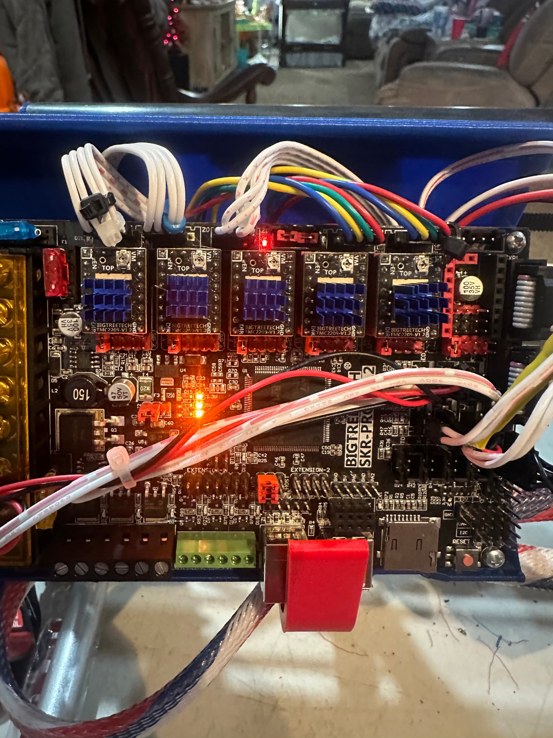
I will try to explain this without getting overly confusing. Basically I tried to home the z axis first the non rail side stepper was going down, flipped the stepper wire and that is working properly. The Z steppers do not stop they make a clicking noise and seem to be trying to keep going. I have tested all my limit switches and everything makes the lights come on BUT the Z stepper on the non rail side which I have labeled as Z1 it lights the control board port E1 which does not have a driver installed, yet does plug into the limit switch port labeled E2. Also with out any limit switches triggered there is a light on beside the jumpers port Z1. For reference I have used Y1 and Z1 for the non rail side and Y2 and Z2 for the rail side.
Port E2 light on when limit switch for Z1 triggered

Z2 light comes on when limit switch for Z2 triggered

How I have it wired
light on with no limit switches triggered
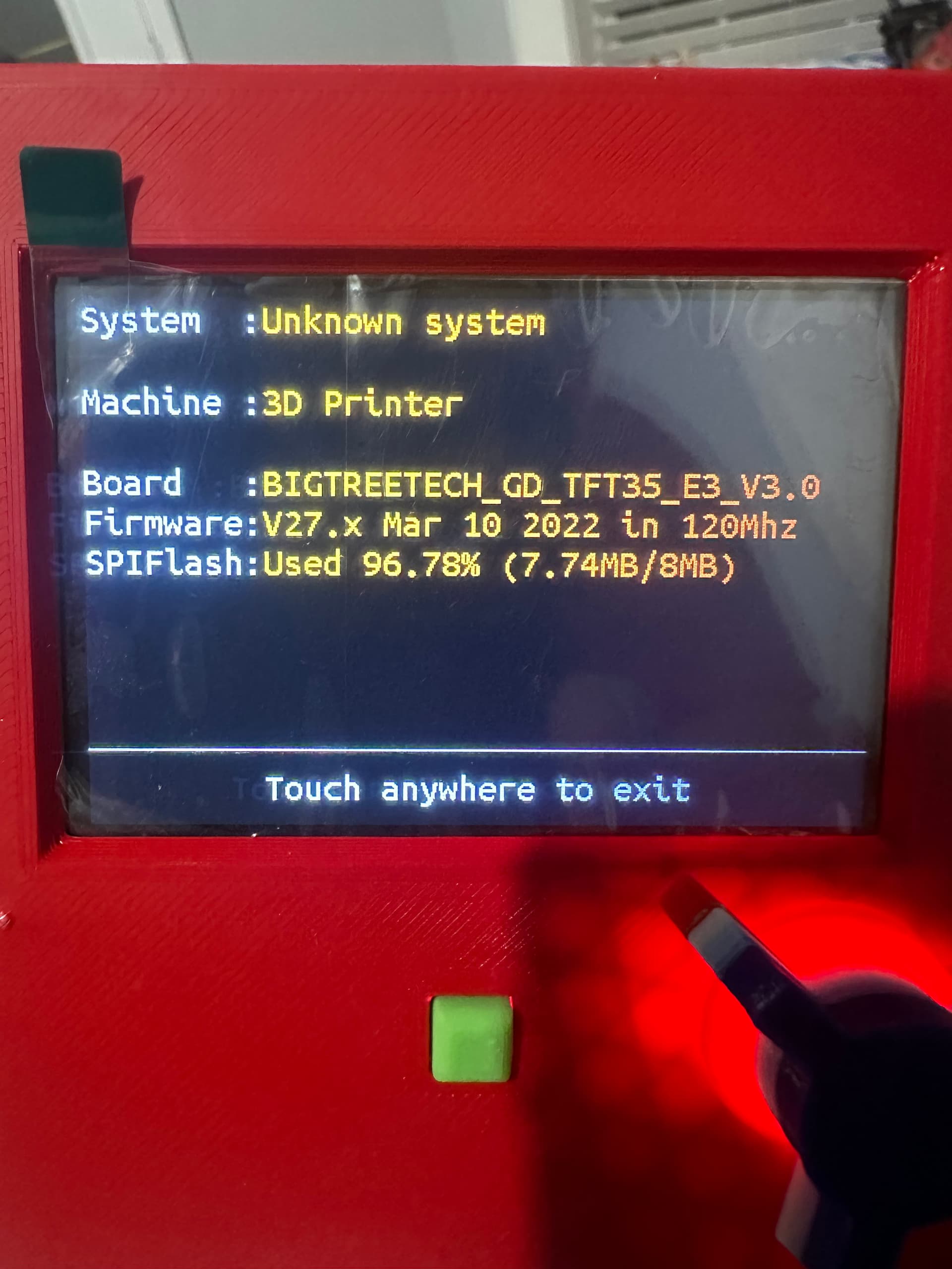
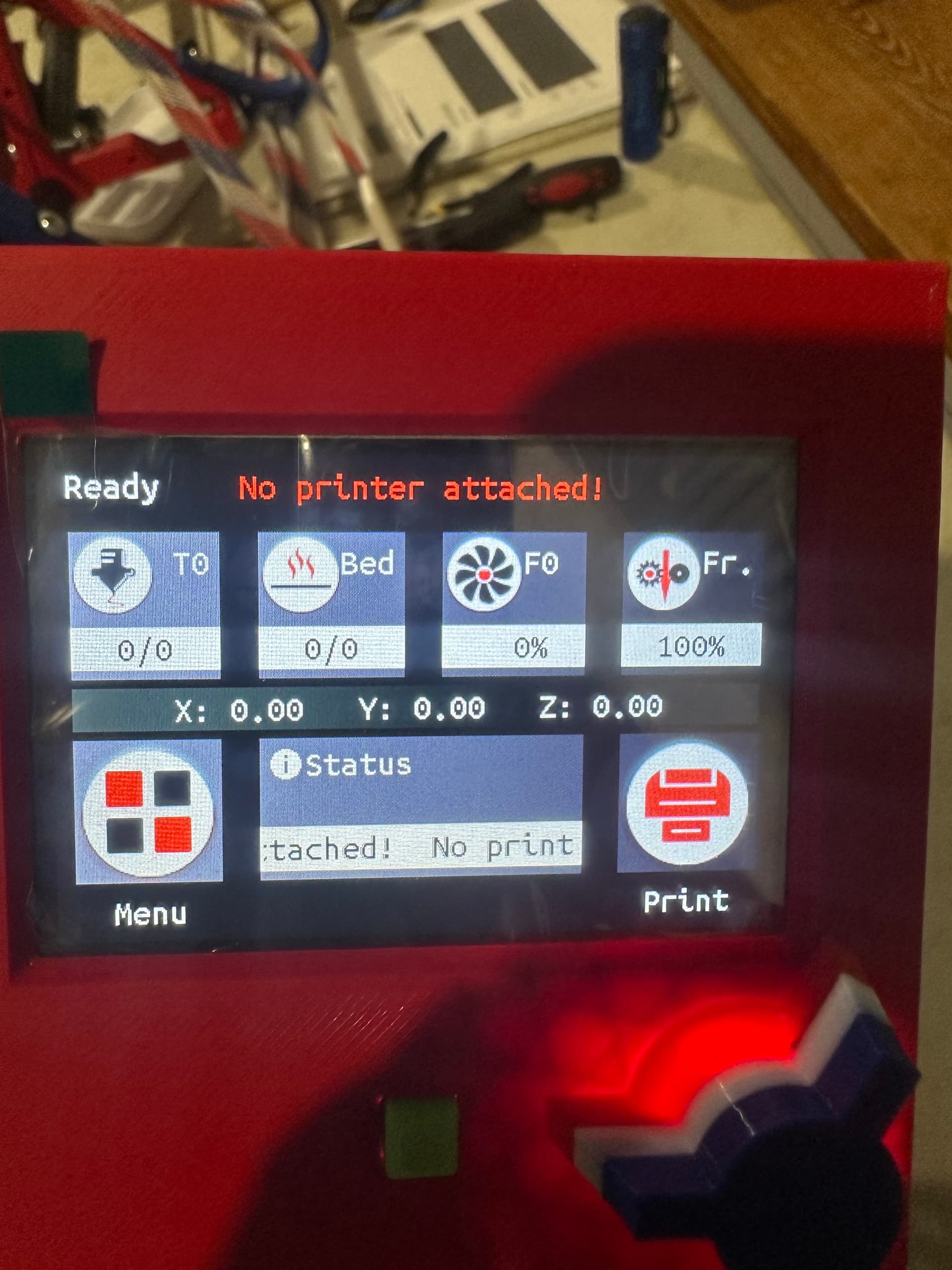
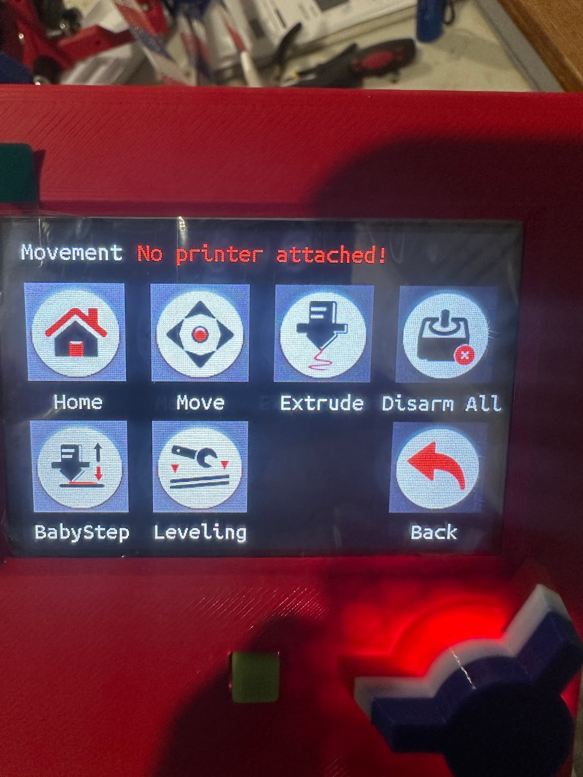
Trying to figure out what software version I have installed I found that the software shows 3d printer is that right? I have also attached the versions and info screens I found. This was supposed to be flashed when I bought it for the lowrider3. Do I need to update the firmware? If so do I have to do it in order or will the latest release simply take care of the missed updates?
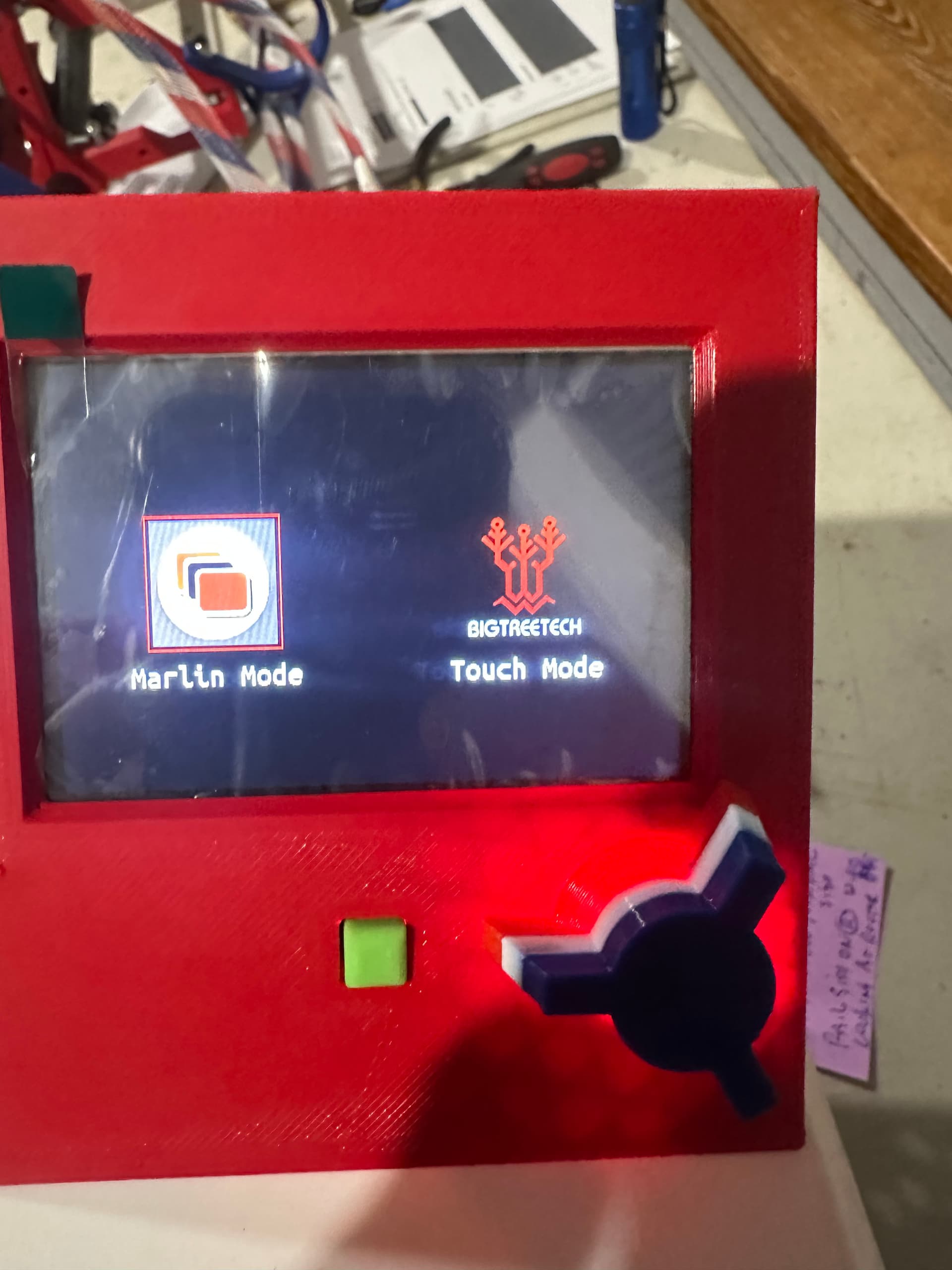
From touch screen
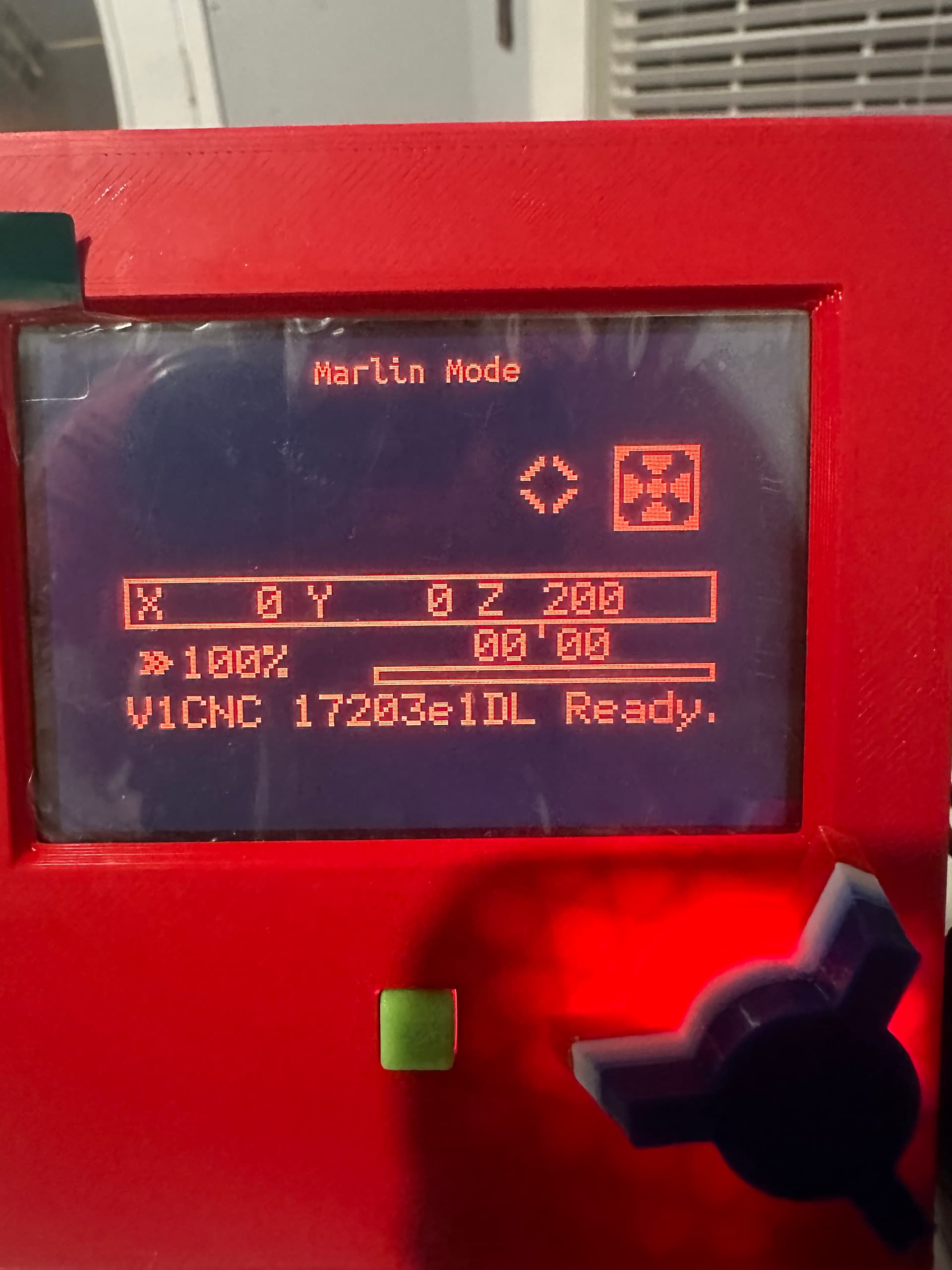
From Marlin mode
Check your end stop wiring.
As per the SKR documentation wiki:
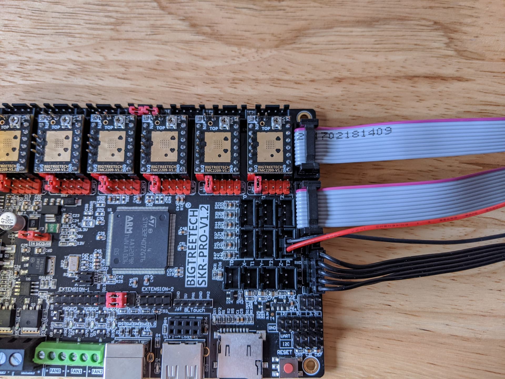
LowRider Dual endstops
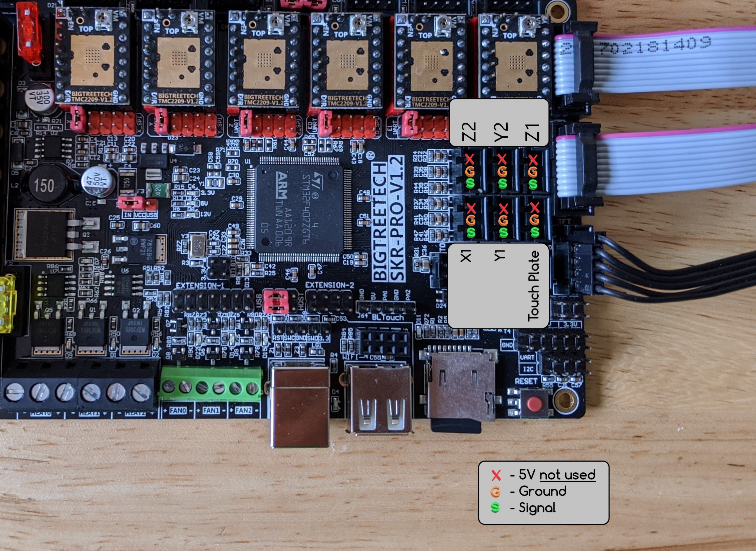
X1 (only X) goes to X (bottom left of picture), Z2 goes to E0 (top left), Y1 goes to Y (bottom middle), Y2 goes to E1 (top middle), Touch Plate goes to Z (bottom right), Z1 goes to E2 (top right). The lights for the end stops don’t exactly match the drivers used for that axis. Not intuitive, for sure!
So E2 on when Z1 triggered is correct. There is no Z1 light activated by the endstops (always on?), but if E0 comes on when Z2 is triggered, then that is correct. (I think you may have Z2 wired to E1)
I think that is the display firmware (not the control board), it looks normal from what I recall. Hold the knob for a few seconds to get to the touch screen (you are currently in Marlin mode, can only enter gcode commands from there).
I edited the pics to help. The top one is from the touch screen mode then went to info. The bottom one is is marlin mode and could not find any firmware version there.
I don’t recall how to view the controller firmware, but if you bought it from Ryan, there is a 99.99999% probability that it is correct.
1 Like
MIND BOGGLING.
So the light for Z1 should or should not be always on? I am going to have to get the multi meter out over the weekend and find out which end stop wire is which for sure. I did not label them thinking it should be simple enough and they should be connected to its stepper. But now I am in an electrical nightmare, or I am overcomplicating it. One or the other.
I did buy it from him, but that was a year ago and I am seeing updates on the github. Hopefully he will see this thread and give his input!!
Or you could just activate the switches in sequence and follow which lights come on.
Z driver (3rd in line) light is activated by the touch plate., E0 driver (4th in line) is activated by Z2 switch, E2 driver (6th in line, not populated) is activated by Z1 switch.
I don’t have my machine powered up right now, so I can’t verify, but I think that there may be a light beside the Z1 connector (which has jumpers installed and doesn’t have a driver associated with it). It is showing lit in all of your photos, so it may be always on.
Sorry, that is confusing. The drivers are labelled X, Y, Z0, E0, E1 & E2, while the motors and endstops are labelled X, Y1, Y2, Z1 and Z2. To add to the confusion, there is a Z1 connector that is unused (jumpered with no corresponding driver).
I meant to say that the Z1 connector light may be on, and that it is not activated by any switches. It shows lit on all of your photos. (earlier post edited for clarity)