Touch plate make sense because it is reading open right now which would trigger a light.
Activating the switches is how I got to where I am now I thought that was a good way but now I am second guessing myself.
COOL SIDE NOTE I was just going through my pics and looking at the one labeled “how I have it wired” the second connector from the left with a blue zip tie looks like it is not on the pins right. Looks like there is a pin exposed. Something else to dig into when I get back in front of it!
1 Like
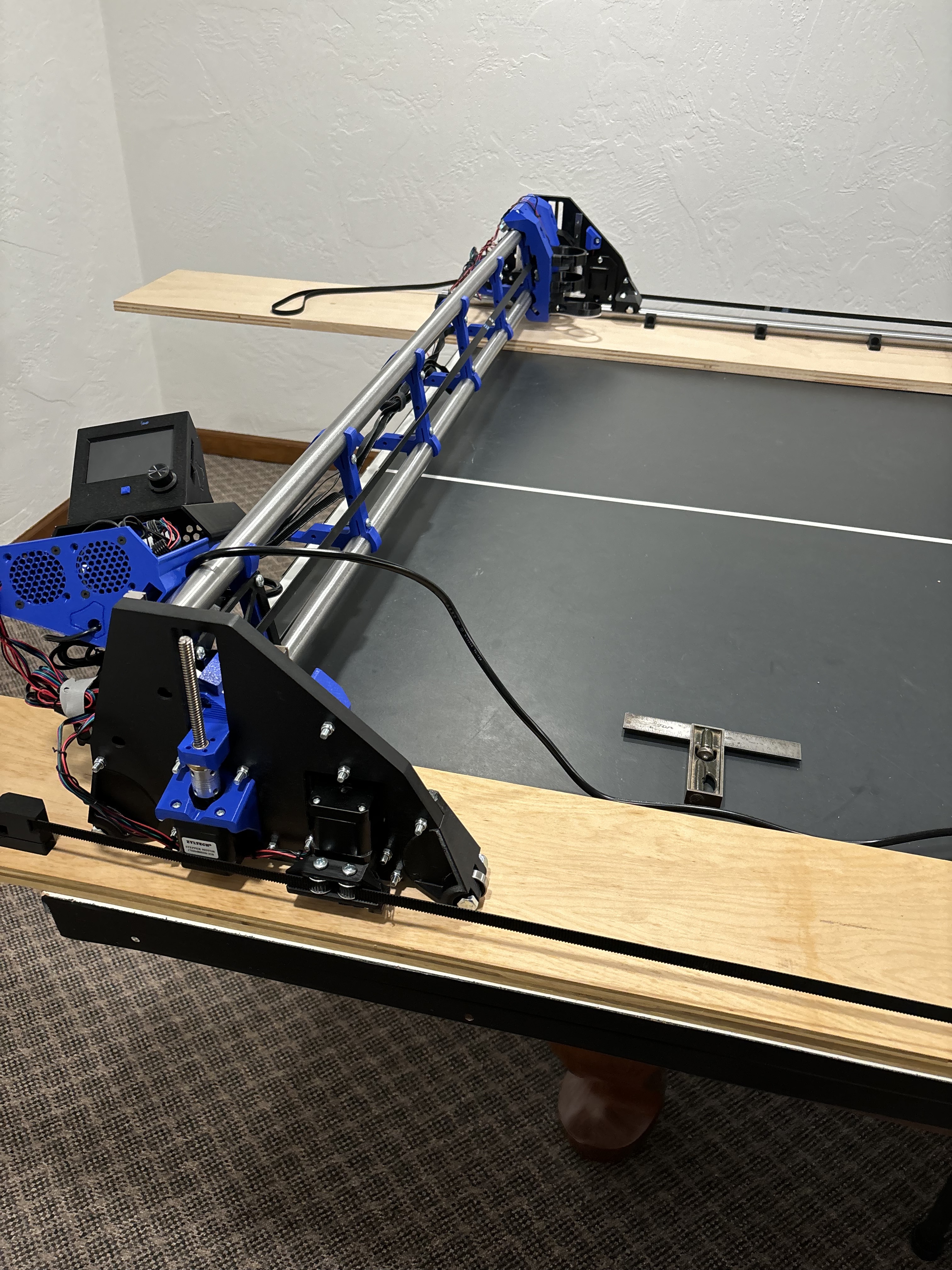
That last picture looks like what I have on my machine. You can select the MOVE or HOME screens to operate the LR3 manually. Most of the other buttons aren’t used.
The “No Printer Attached” message may be an issue. That message usually clears on my machine after a few seconds. You may need to check your wiring or Baud Rate.
I had some confusion when checking my end stop wiring, because from any distance it isn’t hard to confuse which light is with which connector (tip - the lights are on the power connection side of the driver connectors, not the display connector side)
Rather than relying on the lights, I found using M119 commands (Repetier-Host or Pronterface connected to the controller board via USB) gave me much easier to understand results.
“No Printer Attached” means that the serial connection (black cable) from the LCD is wrong, or the LCD firmware is configured wrong.
Possible causes:
-
The cable is plugged into the wrong port on the LCD. There are 2 5-pin ports on the LCD, I believe that the correct port is labelled “RS232.” It should have the keyed JST-XH connector in it
-
The cable is plugged in incorrectly on the SKR Pro side. The other end of the cable is unkeyed, so it can be plugged in backwards. There is one separated dupont connector pin, it should be closest to the grey cables.
-
Incorrect baud rate. V1 firmware is configured to talk at 250000 baud on that port, the config.h file on the LCD should have that selected. If jt was not reconfigured by you, that should already be correct.
While it says “No Printer Attached” the touch screen will not work at all.
3 Likes
This is sometimes caused by the Z endstops being switched. Z1 motor will trigger the Z2 endstop, which stops the Z2 motor, but not Z1. The clicking is not destructive. It is the motor shaft skipping steps, which is aligning with a new magnet quickly, not slipping gears.
The lights are not a great way to tell the endstops are working. After you fix the no printer attached issue, you can send M119 in the screen and see what the firmware thinks the endstops are doing.
My guess is you at least have Z1, Z2 swapped. There may be some other gremlins in there too.
2 Likes
Ok I had a stepper connector not installed properly, the second one from the left in the how I have it wired photo above. Correcting that removed the no printer attached message.
I switched Z1 and Z2 end stop wires and the same thing happens however it moves form the rail side to the non rail side.
I do not know how to use the M119 you mentioned can you elaborate or is there another issue I need to address first?
The cable is plugged in as you show to the LCD and the single connector is closest to the grey cables. I found a stepper motor plug that was not installed correctly and not sure how that plays in but the no printer attached message is now gone.
Just can not figure why the Z steppers are not working correctly.
1 Like
Now that the NPA message is gone, you can use the touchscreen. Go to the terminal function and enter in M119 and hit send. It will then give you diagnostic results for the end stops.
1 Like
am I supposed to do anything while this is going on? photos show the results when I did that.
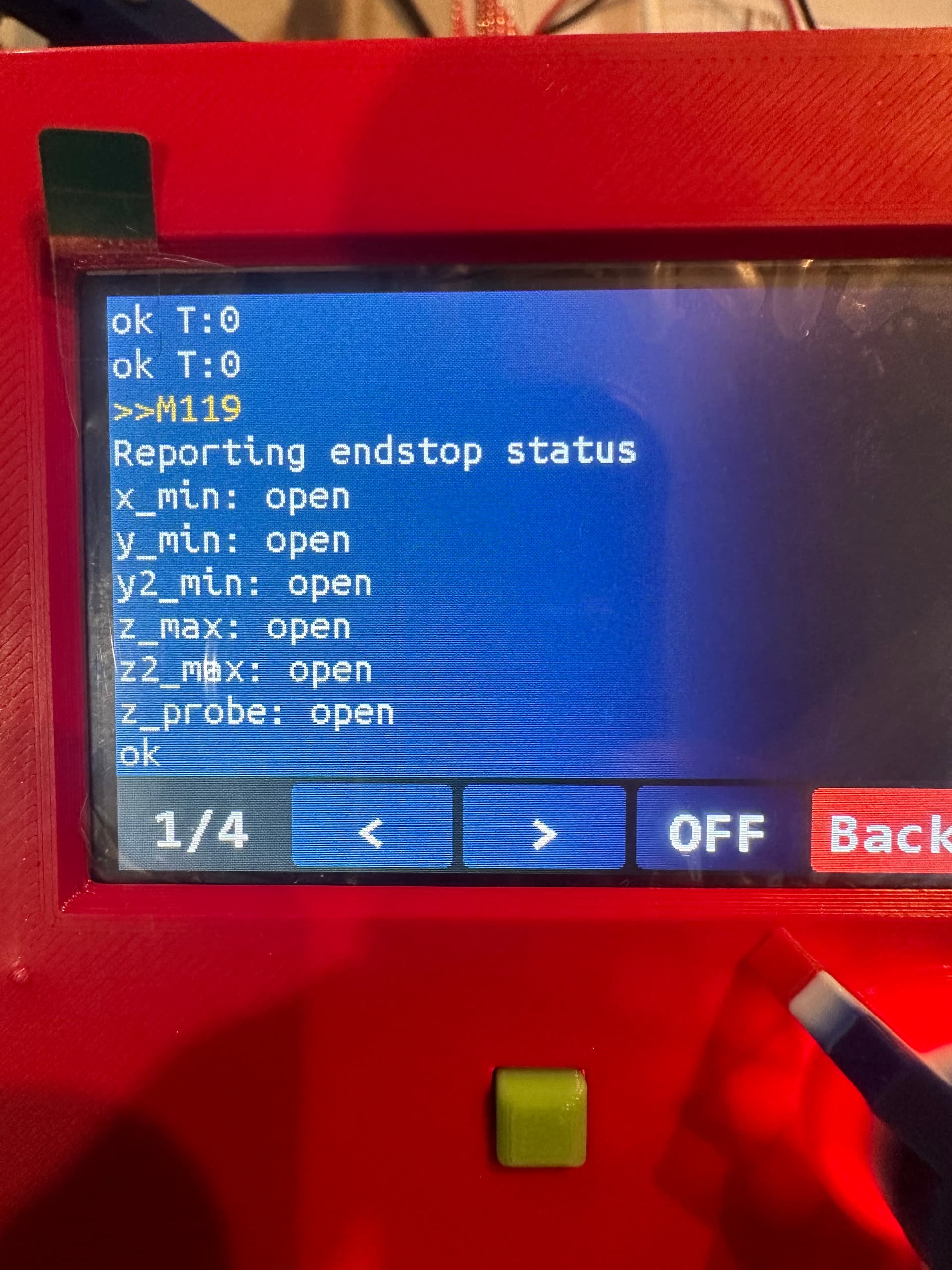
then it just kept doing this

I pushed the “OFF” button just to see if anything changed and this showed

It has been a while for me. But you can press back and send M119 again, while pushing one of the switches to see which one Marlin thinks it is. All open means none of the switches are oressed (that’s good).
2 Likes
Agreed, test each one, one at a time.
1 Like
test results:
rail side Y= Z2 max triggered
rail side Z= Y2 min triggered
non rail side Y= Y min triggered
non rail side Z= Z max triggered
touch plate= Z probe triggered
So you have y z side 2 swapped?
is that as simple as swapping the end stop plugs on the control board and either retesting or trying to home Z?
1 Like
What about X?
1 Like
Yes, power off the board before touching any wires.
Have a look at the SKR instructions for the exact ports you should be plugged into.
2 Likes
So I swapped those two and VIOLA everything is working as it is supposed to at least at this point. I am not mounted to my table yet so I had to manually trigger the Y stops BUT Z homes properly without any obnoxious noises, X homes, and Y homes when manually pushed!! Both from the marlin side and from the touchscreen sides. I can even move the machine around with the touch screen control.
THANK YOU!!
2 Likes
X triggered right, I didn’t really include it since it has been working from the start without any issues.
See my last post reply to Ryan, everything is magically working. Its like a big relief.
1 Like
Nice congrats!
1 Like
Looks great! I thought of doing this too, but wondered how it would hold up. Found some really expensive metal dyes online too, but ended up sanding my pipes and coating them with Fluid Film to prevent rust. My standard steel pipes came out looking like stainless!
My sanding process was a little different - I made a roller bracket so I could spin them (used my Shopsmith, but a drill would work too) Made sanding quite a bit easier but still took a couple hours to do all three (2x5ft, 1x6ft).
2 Likes