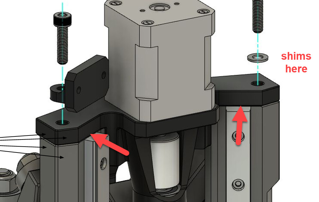
I was able to get there though I don’t really understand why it is occurring (as in where the root cause is, but I suspect the rail mounts are maybe warped). To fix it, I added some shims below the front edge of the Z stepper mount to adjust the angle of the bearing and coupler relative to the screw coming up from the router mount. Thanks for the pointers.
1 Like
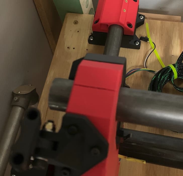
Hi again! Another quick question. Should the X rails be perpendicular to the inside faces of the two uprights? I am mounting to my table and can’t seem to get it square and can see the X rails are not perpendicular to the uprights. I am also seeing a crack at the top of the left upright so I am assuming I am imparting some stress where I shouldn’t be in my attempts to square the base. I am inclined to loosen the X rail clamps to allow the adjustments and re-tighten, but if they are intentionally not perpendicular, I can look elsewhere for the issue. Thanks in advance!
They should be perpendicular to the inside face, maybe a little bump from a print imperfection causing it?
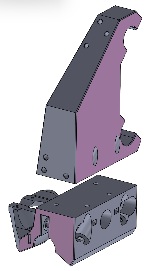
Thanks for your input! I did track the issue down to the printed parts. Turns out to be more than just a little bump though. Not sure what causes it, but the prints are not perpendicular. I was able to massage them by using the inside face of the uprights as a reference on a spindle sander and get closer to the mark. It’s Interesting that the two sides were off in opposite directions so something is def. up with the printer (An Ender3 and the prints were oriented 90 from each other to fit the bed so sort of make sense). I guess I need to do some digging on that front. Anyway, I am now facing a different problem (likely also an issue with my printers.) The uprights are cracking along the layer lines at the top. I was very very careful to limit the screw pressures when assembling the upper clamps, but cracked anyway. Have you experienced anything like that in your efforts? I have attempted to modify the part files in an attempt to print in two pieces to both maximize the layer strengths and minimize the perpendicularity issue. (Pink sides are facing bed). Bolting together with four M5 Bolts and nuts. Any thoughts on taking this approach?
1 Like
Dave,
I had a similar situation. At first I just put glue in the crack. It held for a few months. I then reprinted the uprights using a 0.6 mm nozzle. You could even increase the infill or even the perimeter count (and if you have a fancy slicer, just do that for that section of the part).
Just some other things to try/think about. I’m no expert, just sharing what I did and how it worked out. ![]()
Hi Matt,
I have been debating about doing the same (glue) just to get it up and running but taking it all apart again to replace the uprights is making me pause. Last night I was reading that I may be my own worst enemy on this. I printed the parts using Duramic Matte PLA. I love the look, but I dug thru a bunch of data sheets and user reviews/posts that indicate matte PLA has very poor layer adhesion and a raw strength much less than standard PLA. So, I ordered a couple more roles of standard PLA and will print the two-piece versions as a trial. We’ll see how it goes.
1 Like
I personally haven’t had a split where the layers separated, I use PLA+ mainly and a .6mm nozzle.
I would add some kind of registration (pin, slot feature) to make getting them lined up easier, dont really see a reason not to give it a whirl.
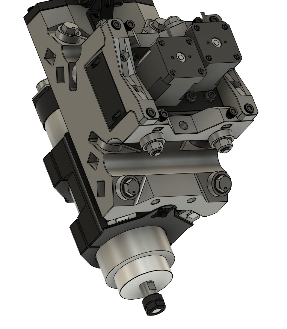
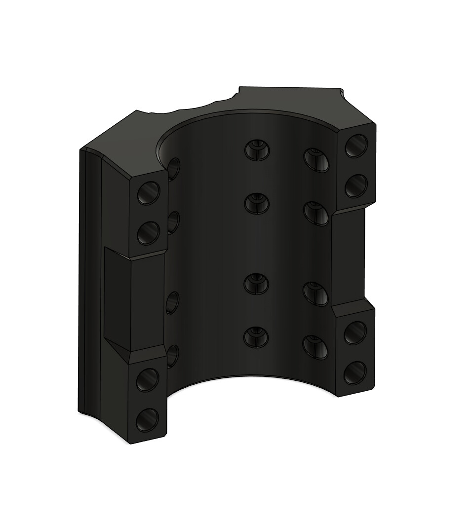
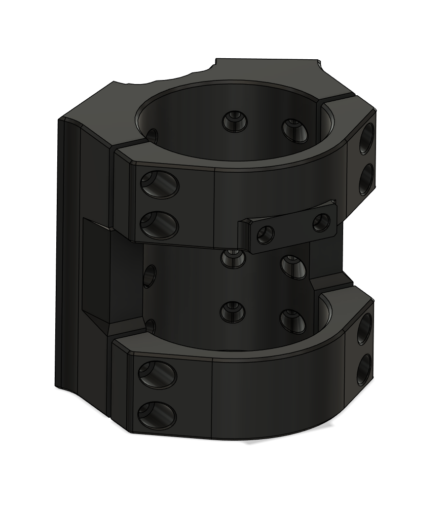
Throwing another change in to the mix since I finally have a little time to get back on this, there will be 2 separate caps to hold the spindle to the mount. Should cut down on some filament, make installing the mount easier, and should the caps stress fracture will mean a lot less reprint time/filament.
3 Likes
Oh sweet baby Jesus colour me excited.
5 Likes
Thats a shade lighter than Tickled Pink right? ![]()
4 Likes
Too funny…never heard a reply quite like that before!
1 Like
Absolutely! Lol
1 Like
It’s probably the Aussie in me.
2 Likes
4 Likes
Looking brilliant man.
1 Like
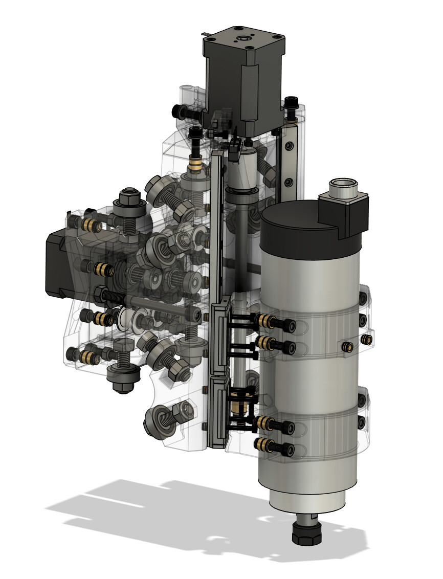
I got some more filament in the mail, some more threadserts on hand, and most of the small details ironed out. Mainly just need to order some hardware and print it now!
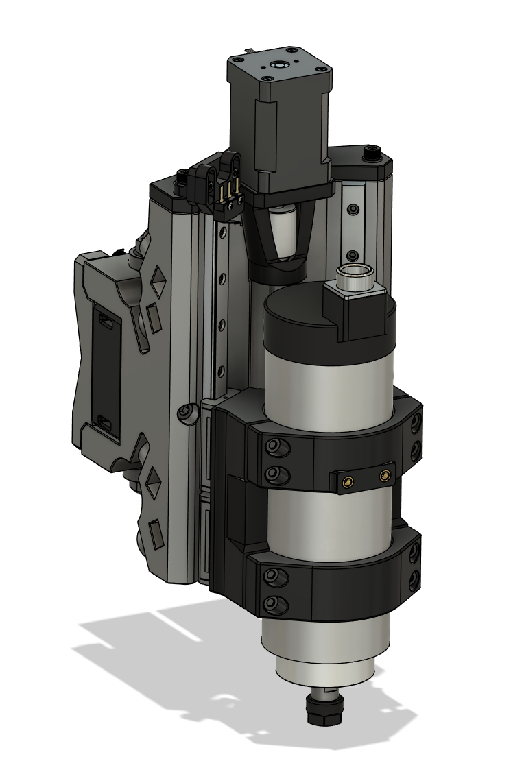
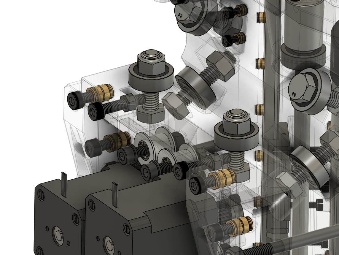
Also sorted out how I put hardware in the assembly, makes views like this easy (including how adjusting for tubing OD variation will be handled).
3 Likes
If you wanted a test dummy, I’m more than happy to sink some filament into it!
1 Like
Finally, got there - I apologise for the assault on the ears which is the sharpie on the timber.
I’ve modified the limit switches and PSU location so that the gantry is essentially fully self-contained. It’s fairly cobbled together but it’s going! You’re a legend @Brute71 it’s a sweet design.
")
2 Likes
You are teasing me with the motorcycle bits on the bench!
1 Like