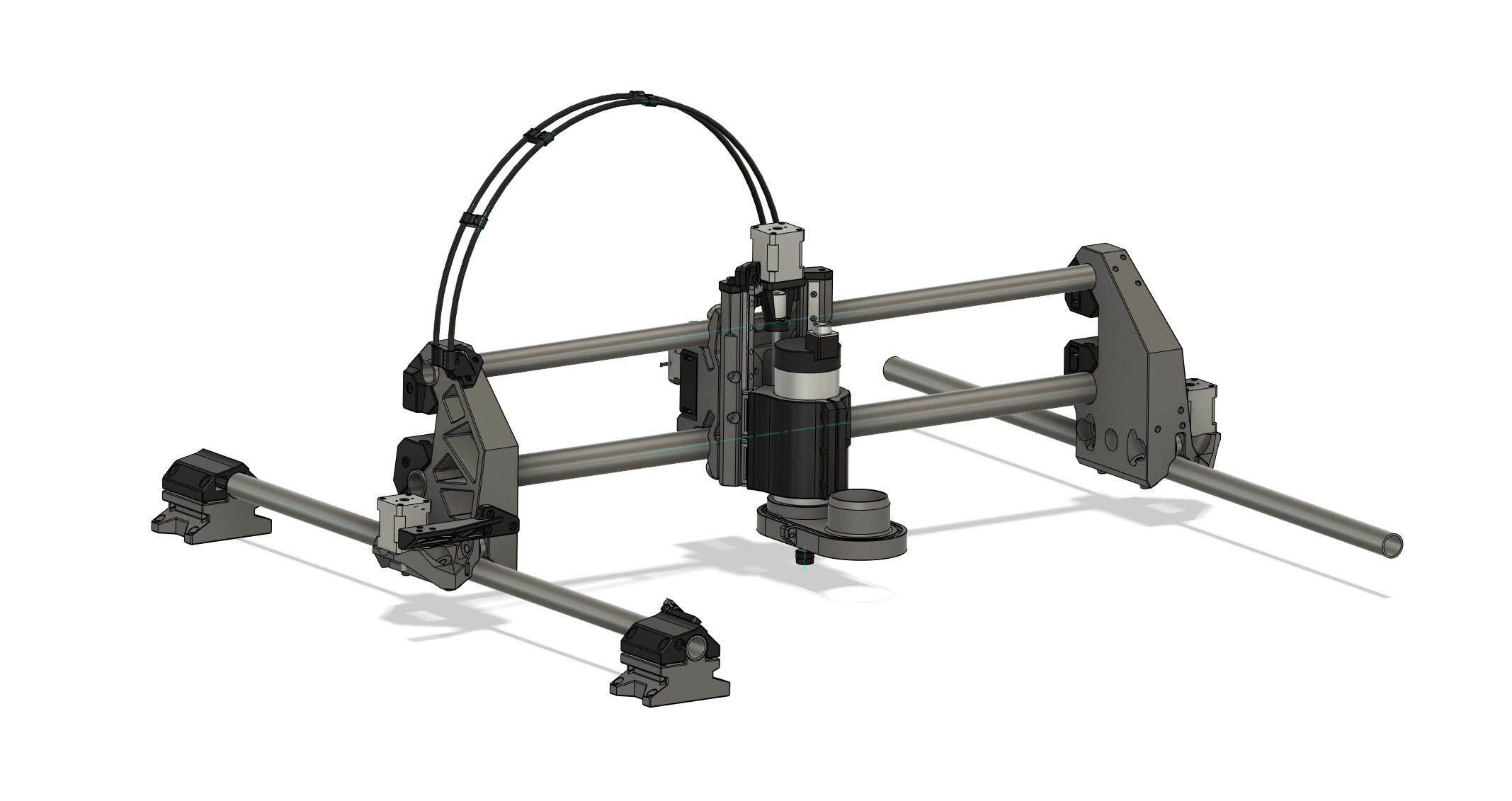
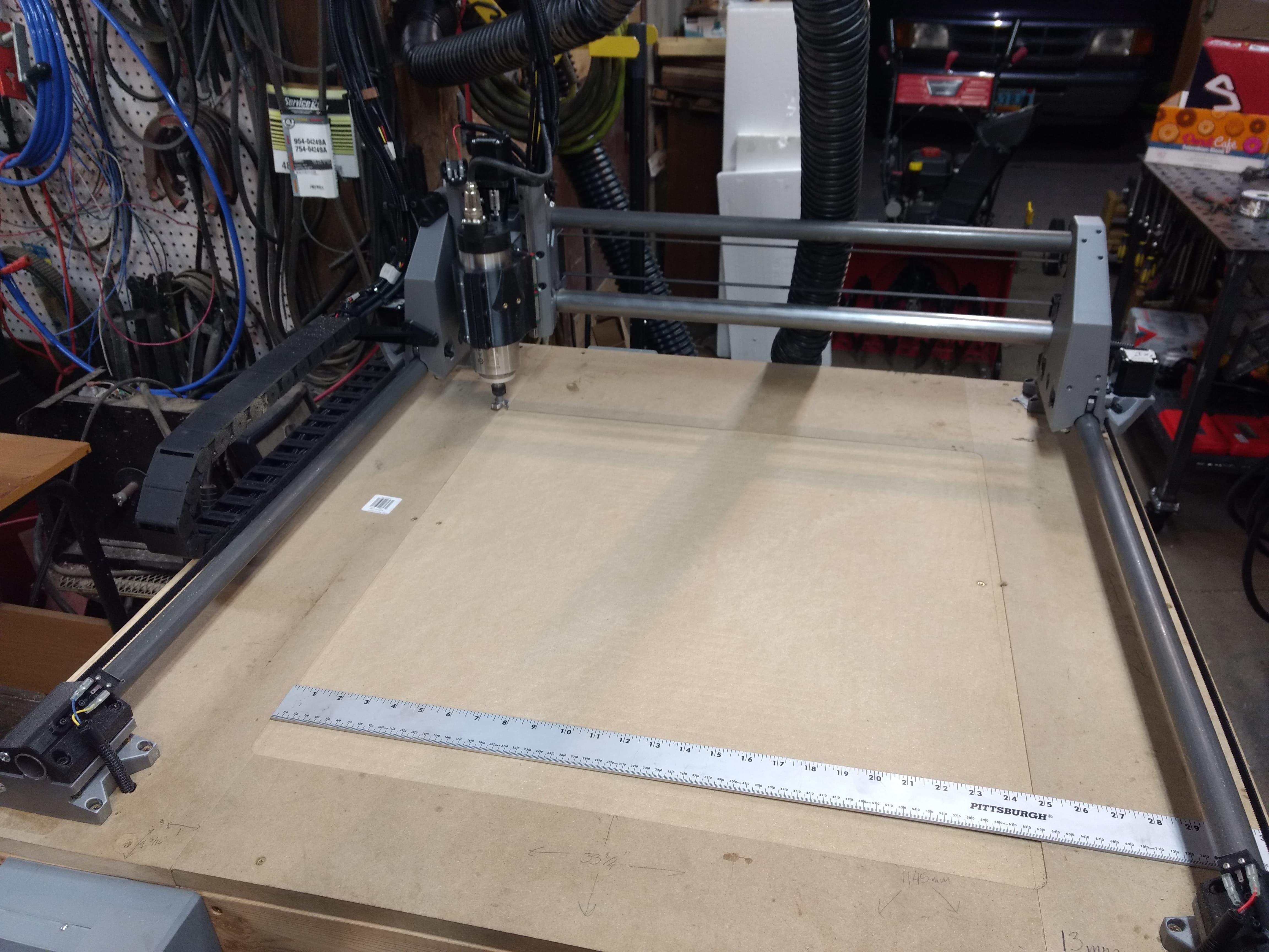
As a sort of design/engineering exercise I decided to make a gantry style CNC that stuck with the budget part of the MPCNC and the MP part. It shares a good portion of the running gear and hardware I pulled from my MPCNC Primo and is designed to use a 65mm spindle. Was somewhat persuaded to post this here, so I figured id start with some build/test progress!
23 Likes
That seems to be an outstanding design!
I even seem some mid-span supports so you could go fairly large in the Y axis. Can’t wait to see it run.
3 Likes
Nice. That looks like fun. Did you enjoy designing it? Do you have a lot of experience with CAD? It looks like you put a lot of thought into it.
3 Likes
Had a blast designing it! I have been using CAD in a hobby/self learning manner for a number of years, always nice to push outside the comfort zone from time to time. Certainly took the time to consider how it goes together and interacts! But sometimes building it is the only way to really see how it all goes together!
3 Likes
I really like what I see. Cannot wait to see it operate!
1 Like
That is pretty beefy. What is the tube diameter you are using?
Uses 1" od .06" wall cold rolled for the top of the gantry and the y axis, 1.25" od .12" wall for the bottom tube on the gantry.
1 Like
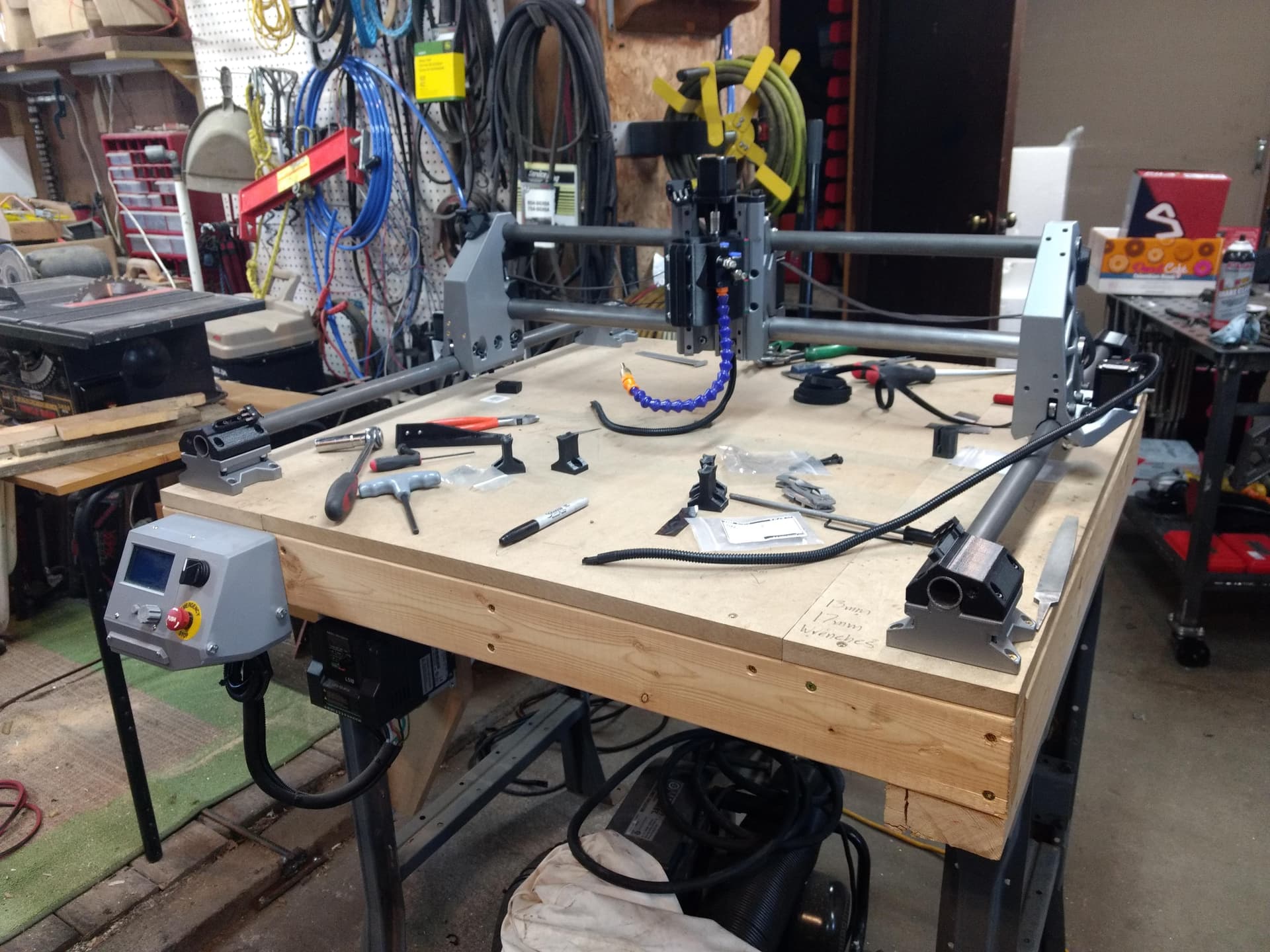
Got most of the wiring done, waiting on some loom to finish it up and started getting the firmware sorted out.
14 Likes
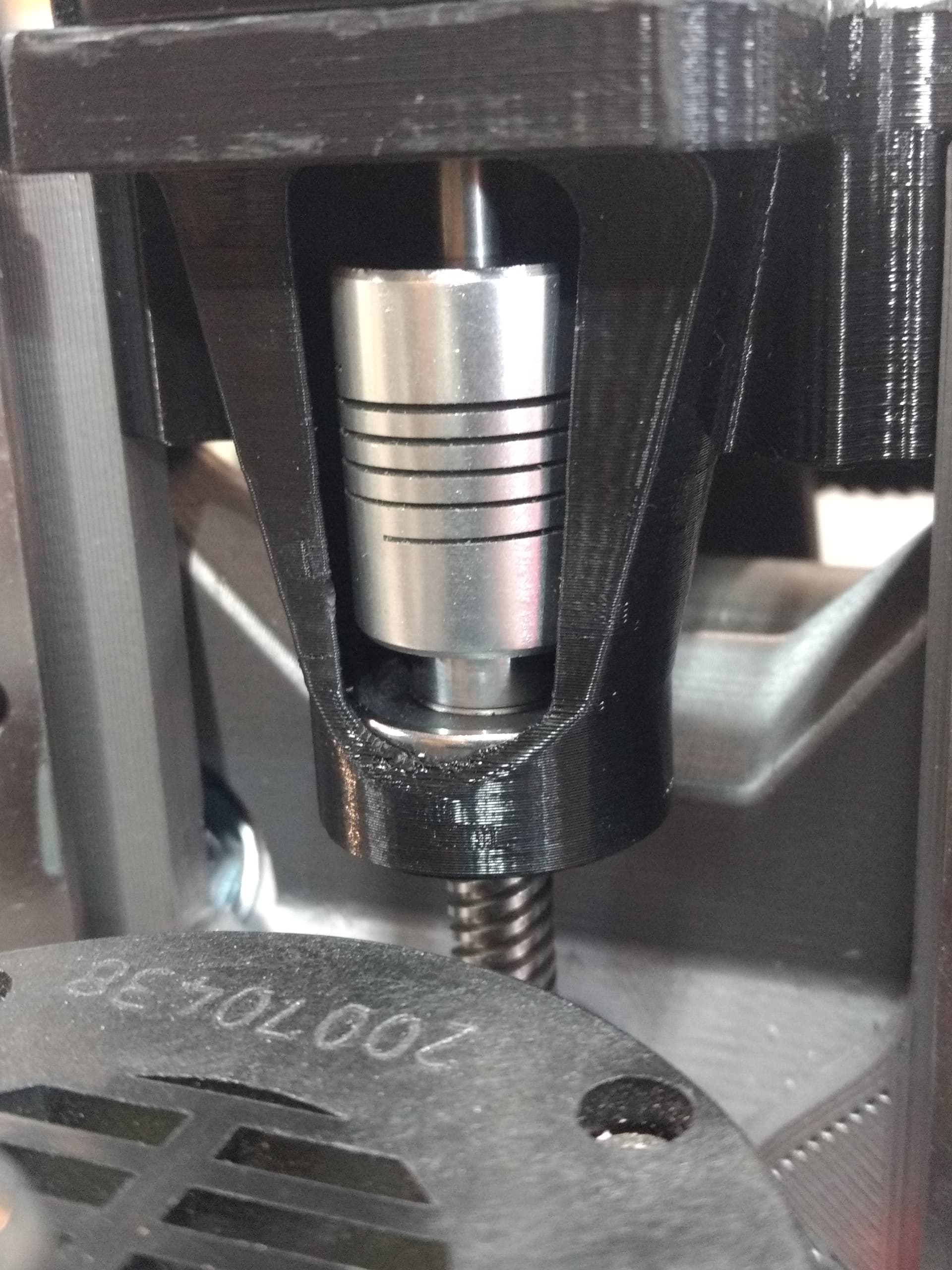
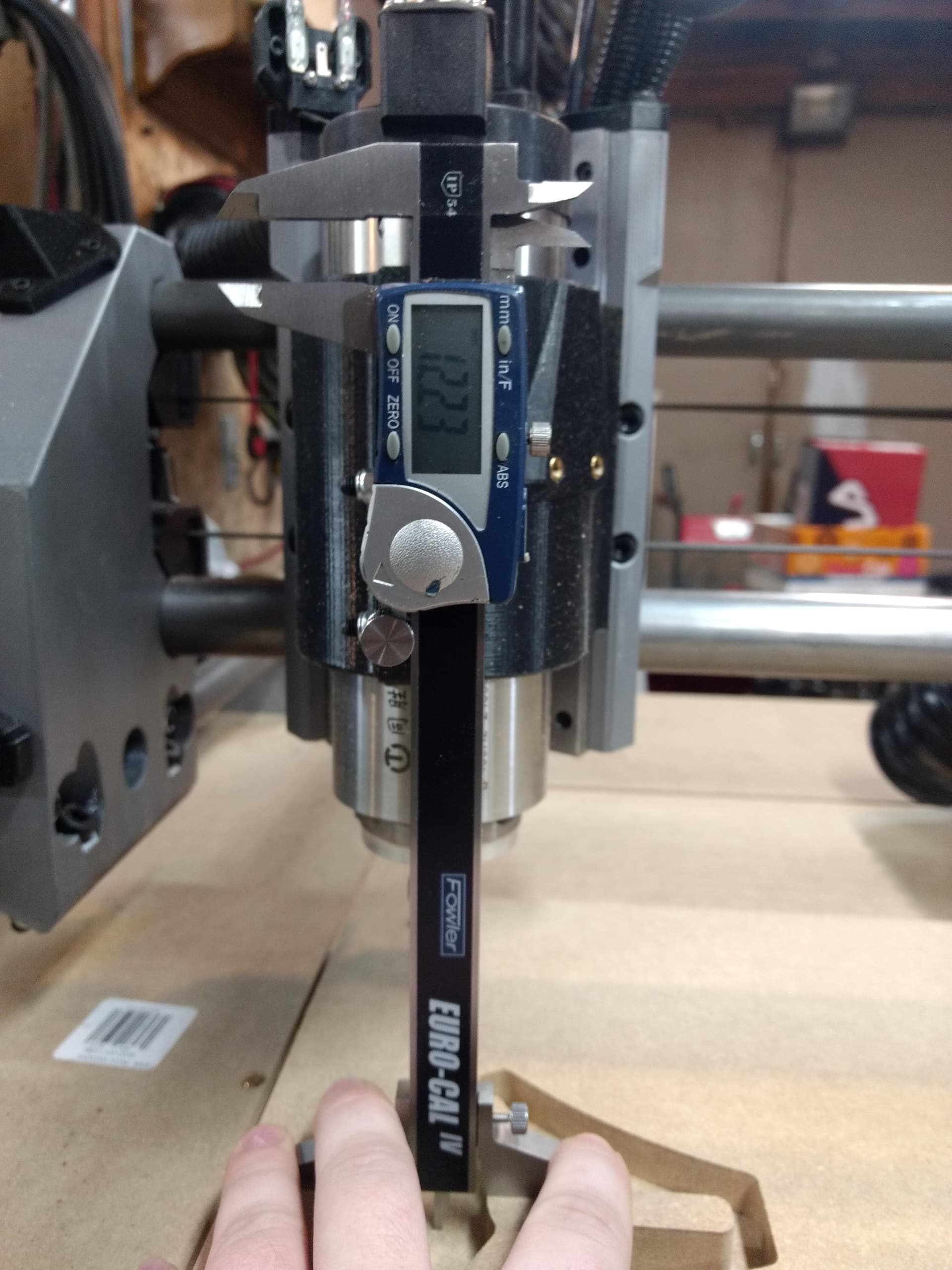
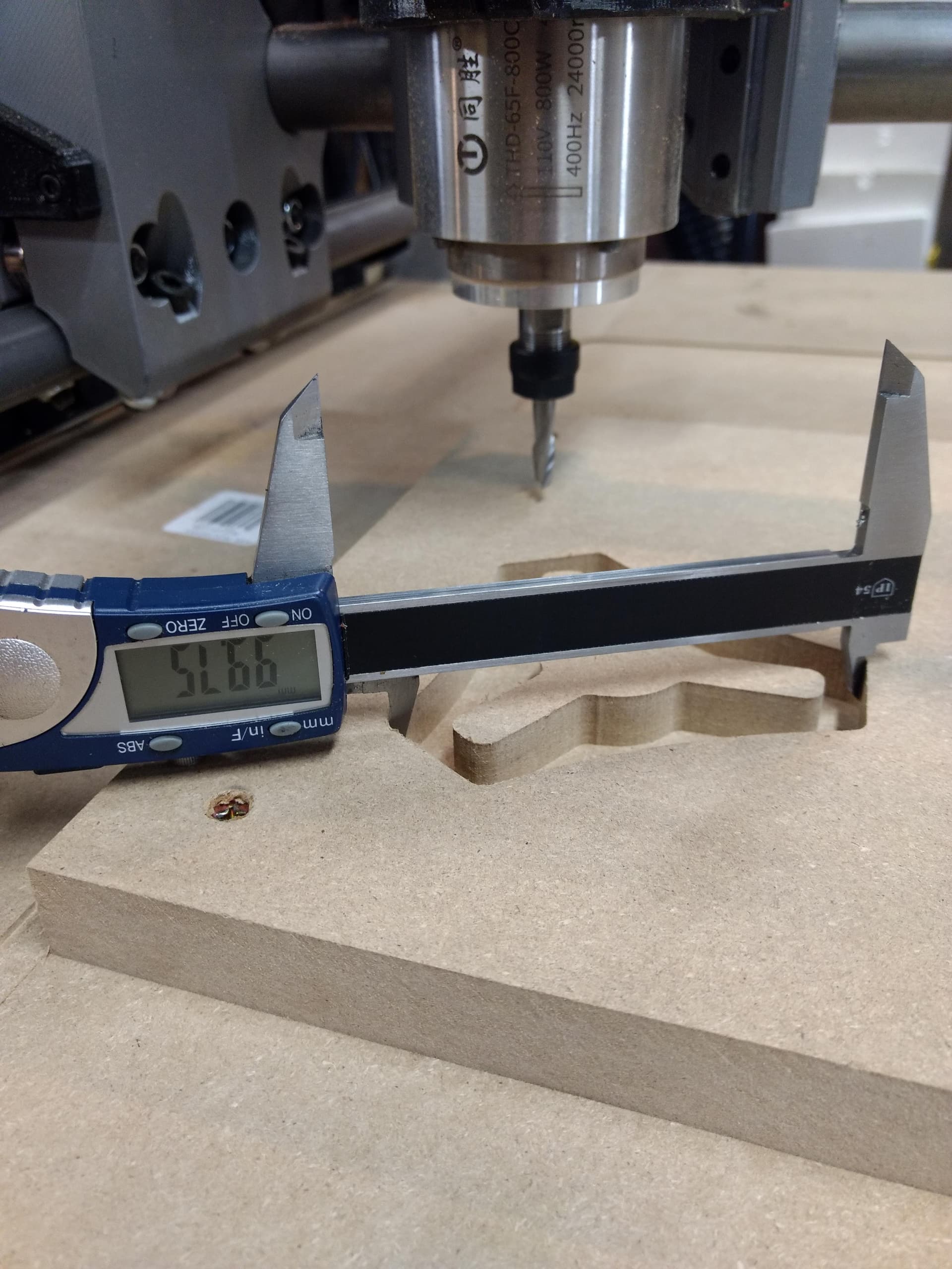
Tool height setter came in today, and of course you have to play with the new tool! Found the backlash to be a little inconsistent between up and down on the Z so I made a short walk over to the lathe and made a spacer to go between the spring coupler and the guide bearing. Backlash is now an even .002" both ways and now I know I will need to account for that .002" for the Z when making parts with a critical depth.
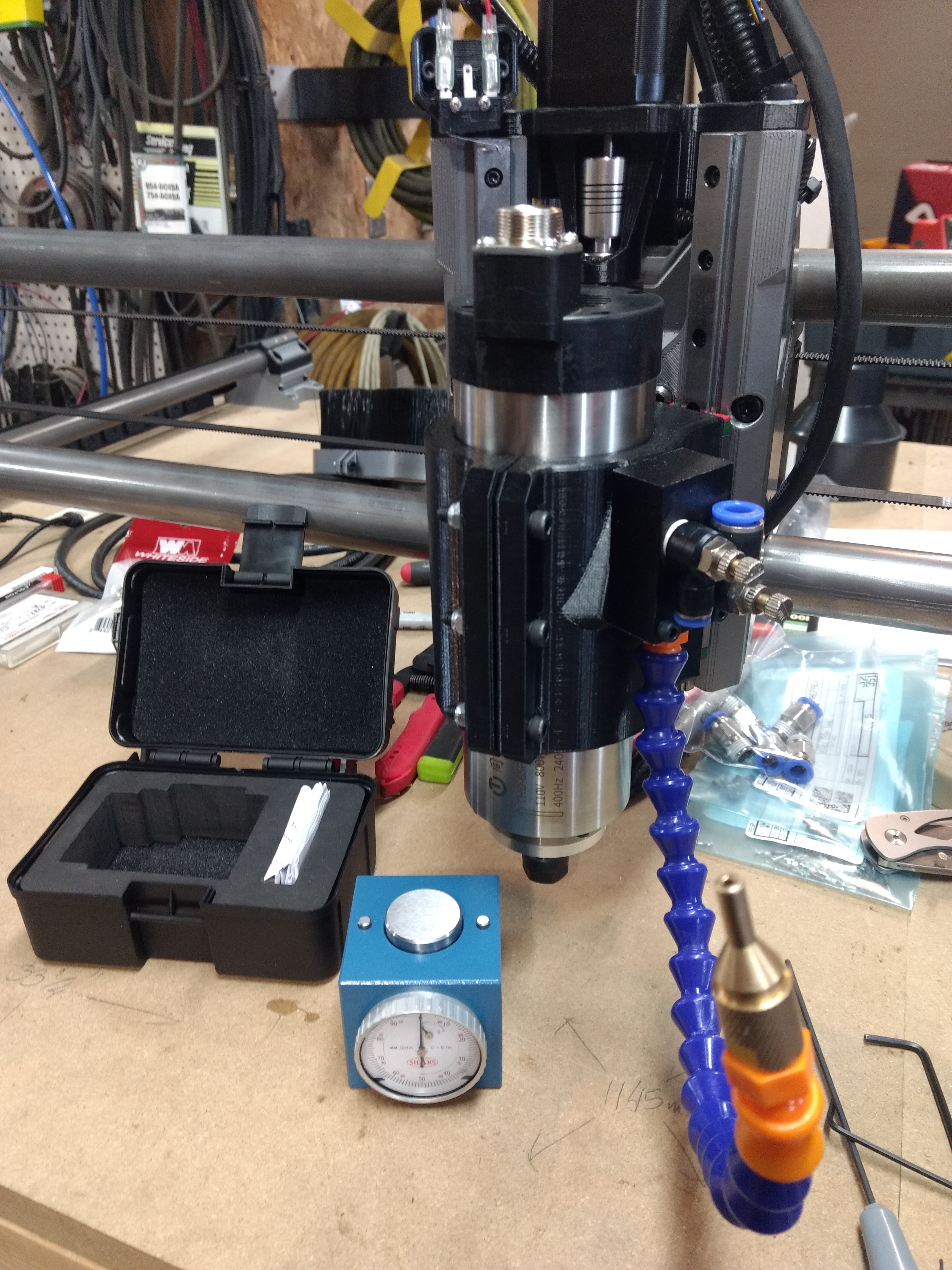
10 Likes
Impressive work
1 Like
Mpcnc amd onefinity making babies?
Looks nice, though…
4 Likes
Those types of couplers are horrible for backlash and critical movement.
You should take a look at Spider couplers.
2 Likes
Looks cool! Do you have a link for the spindle you’re using? I’m debating picking one up for my upgrade.
2 Likes
The way it is now setup limits it to basically just what is in the lead screw nut itself, so it is serviceable. Could just machine a solid coupler too lol.
For the spindle, it is just a run of the mill 800w chinese spindle off ebay like this 110V 800W Air Cooled Spindle Motor 4 Bearings Engraving Mill CNC Waterproof USA | eBay
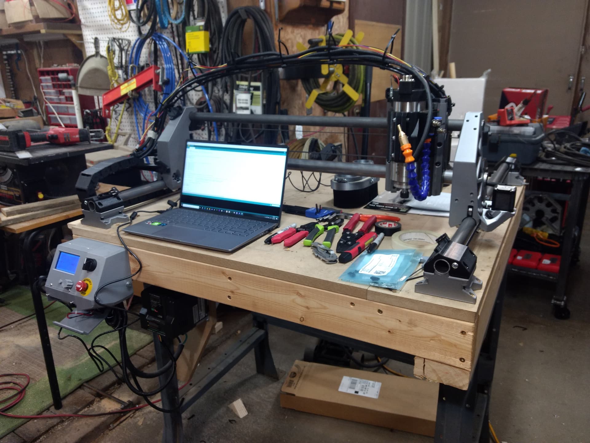
Did get the wiring all finished up today, then got the gantry trammed in perfectly. Ran myself through estlcam again, did an air pass for cutting the spoil board to test everything, then gave it an actual run! Found the hose I have is horrible for the dust shoe (suggestions for more flexible stuff?), and the self aligning part of the z axis worked out extremely well! With the 1" bit there is absolutely no tilt in the spindle and such a slight nod that you can just barely feel a step over if you are feeling for it. I think it is time to run a cnc drag race to push it a little 
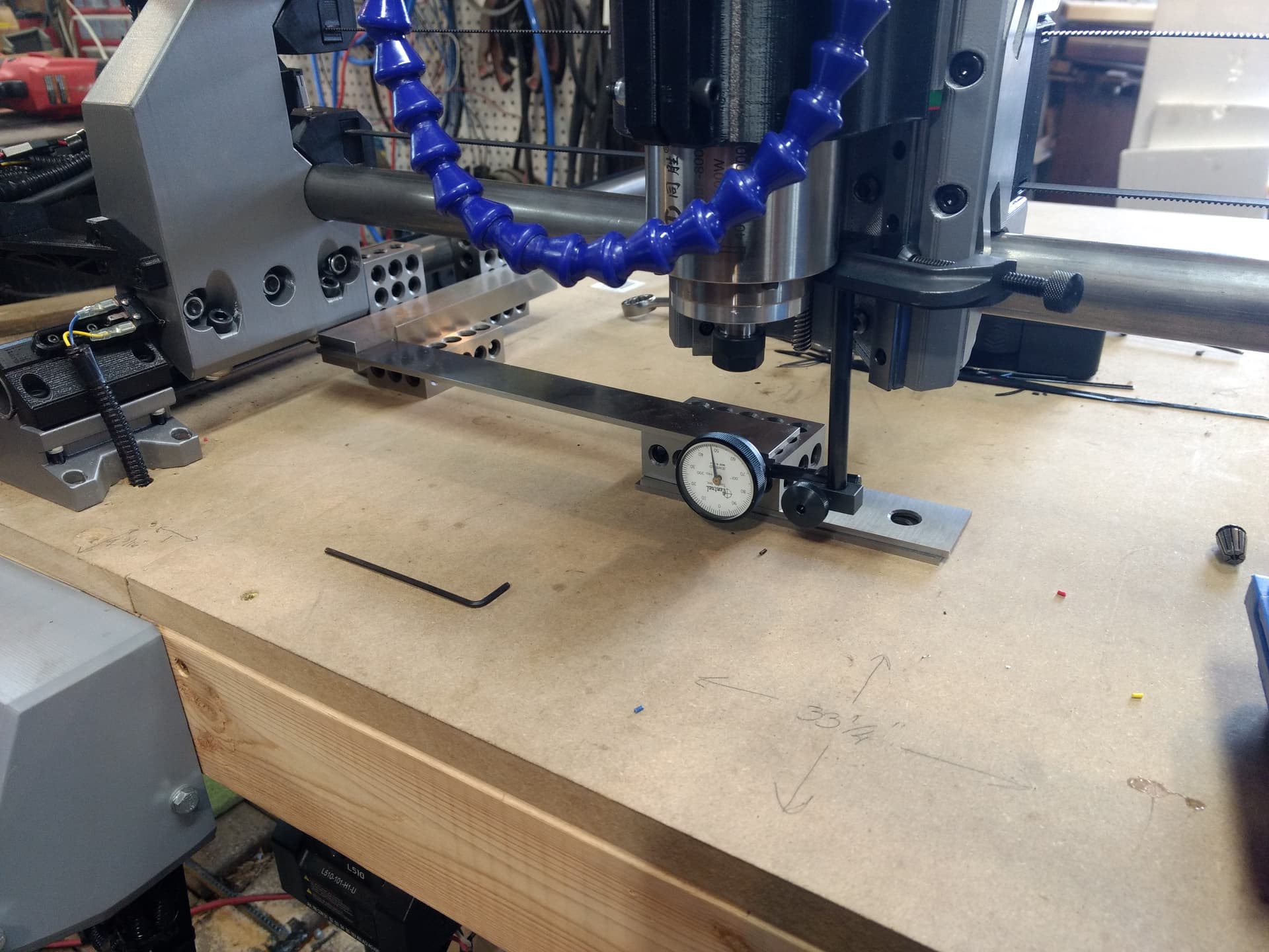
12 Likes
Heck yes. Looks like it will demolish the drag race! I think it is time to run two back to back or switch to aluminum or something. Can’t wait to see it go hog wild.
6 Likes
I think a 32-bit controller is in my future, the rambo 1.3 did not handle the g2 arcs well (random short pauses on the curves, on in test 1) nor is it winning any speed contest with g2 off on the curves. I will say the testing helped break in the belts in short order, were a fair bit looser than I left them after the 2nd run XD Tests had the X/Y at 50mm/s, 12mm DOC on a 1/4" carbide 2 flute end mill.
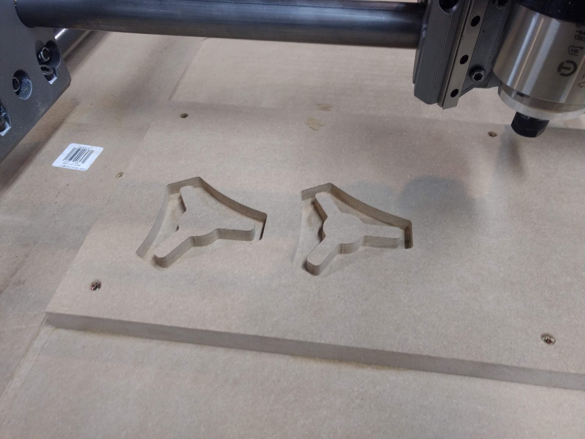


7 Likes
I saw some references to turning on arcs in the race thread. Before digging too deep maybe double check that the dxf is a smooth shape. I mean, it’s a good file that everyone uses, so this is probably not it, but it’s free to check.
I had an issue a while ago where I traced a circle and instead of tracing it WITH a circle, the software traced it with a bunch of tiny line segments. Then i was basically accelerating and decelerating from point to point. The calculations weren’t a bottleneck at all. It was all machine parameter limitations. Looked a lot like that.
Also, in mdf and soft wood, you can really helix in way faster without worrying much, so if you need to pick up an extra 3/4 second, that’s low hanging fruit for you.
Still, looks pretty awesome. Nice job.
3 Likes
Should have been going in faster (I think at least), 25mm/s z speed with a 45* ramp in angle. Still learning the CAM stuff, up until now it has been just CAD and turning handles on a mill and lathe. Thanks for the kind words!
2 Likes