That’s the way it goes some times haha, I know that all too well.
1 Like
Hey Alex…still running and using the Brutus. Currently watching it carve/cut out the bottom of a bowl. I’m still monitoring this to see what updates/changes you come up with.
Hope those ‘other’ projects get out of the way as quick as they get in the way, but as has been said…That’s the way it goes some times ![]()
![]()
1 Like
My indoor hobby season is approaching and I still plan on finishing up that update and doing a little testing on it, so not too much longer and I should be able to post an update!
3 Likes
No worries. Just letting you know there are a few of us watching ![]()
1 Like
I’ll second this, I’m still getting mileage out of mine! I think it’s due for a bit of a refresh, I’d love to get some parts replaced with aluminium.
I also came across these bits;
Cheap, but really seem to chew through aluminium - I thought I might be pushing it with 3 flutes, but it seems to work great - 3mmDOC 1000m/m
3 Likes
Ah man, went to use the brutus the other day and some more parts have cracked - at this stage I’m guessing flood coolant isn’t a go with printed parts. I’m considering the possibility of swapping out some parts for aluminium and seeing how I go.
I guess this is just a heads up to not use flood coolant!
3 Likes
After a closer, less frustrated look, it seems like the original black PLA (the white stuff was godawful and cracked first) is the stuff that’s cracked…Maybe PETG is okay with coolant?
Gonna try it anyway, as the parts I HAVE replaced with PETG all seem fine…
Not sure it is a coolant issue as much as just a PLA thing, but there are plenty of things that you can put in a PET water bottle that aren’t water without it failing.
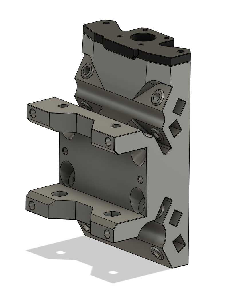
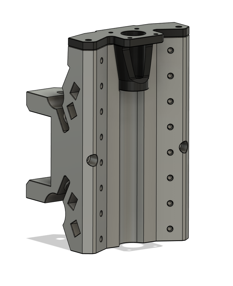
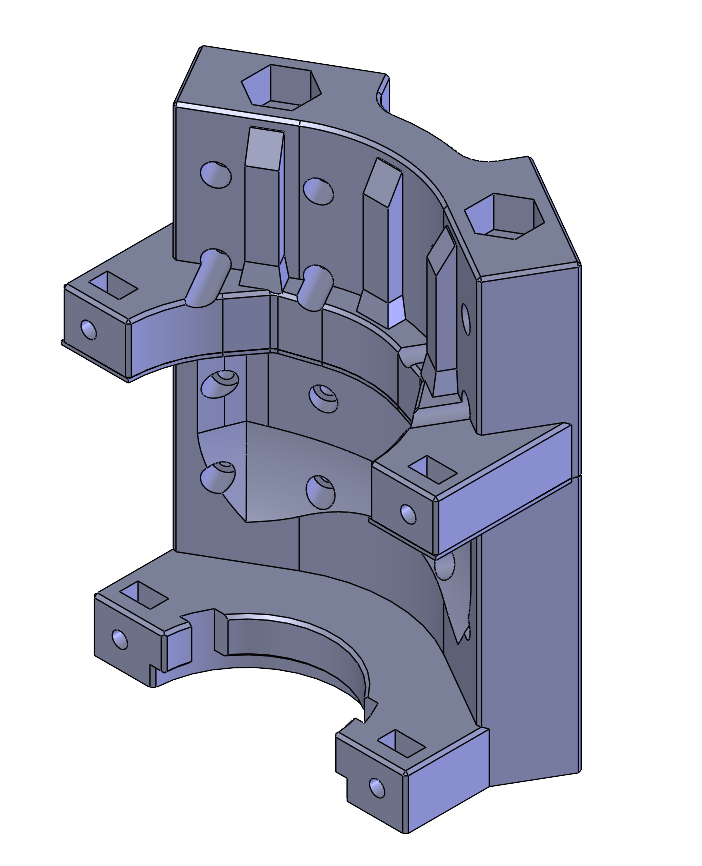
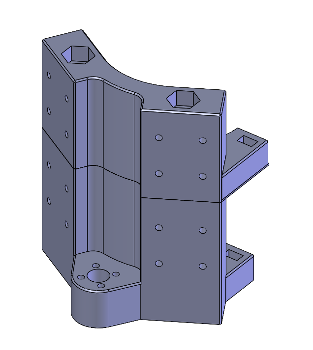
In other news, I have started back in on the carriage revision!
5 Likes
I’ve upped the perimeters this time, hopefully it holds up - when it’s running nicely it’s such a dream to use. This has come at a bad time as I’ve just sorted my tooling
It’s happening!
Little by little! I still need to work out a generic mount for dust collection, a mount for the z-end stop that works with the makita/dewalt mounts, and an idea from Keiz to give an option to have the y-end stops on the uprights vs on the “corner tops”.
2 Likes
It’s looking epic. I’d better invest in some filament to reprint this core.
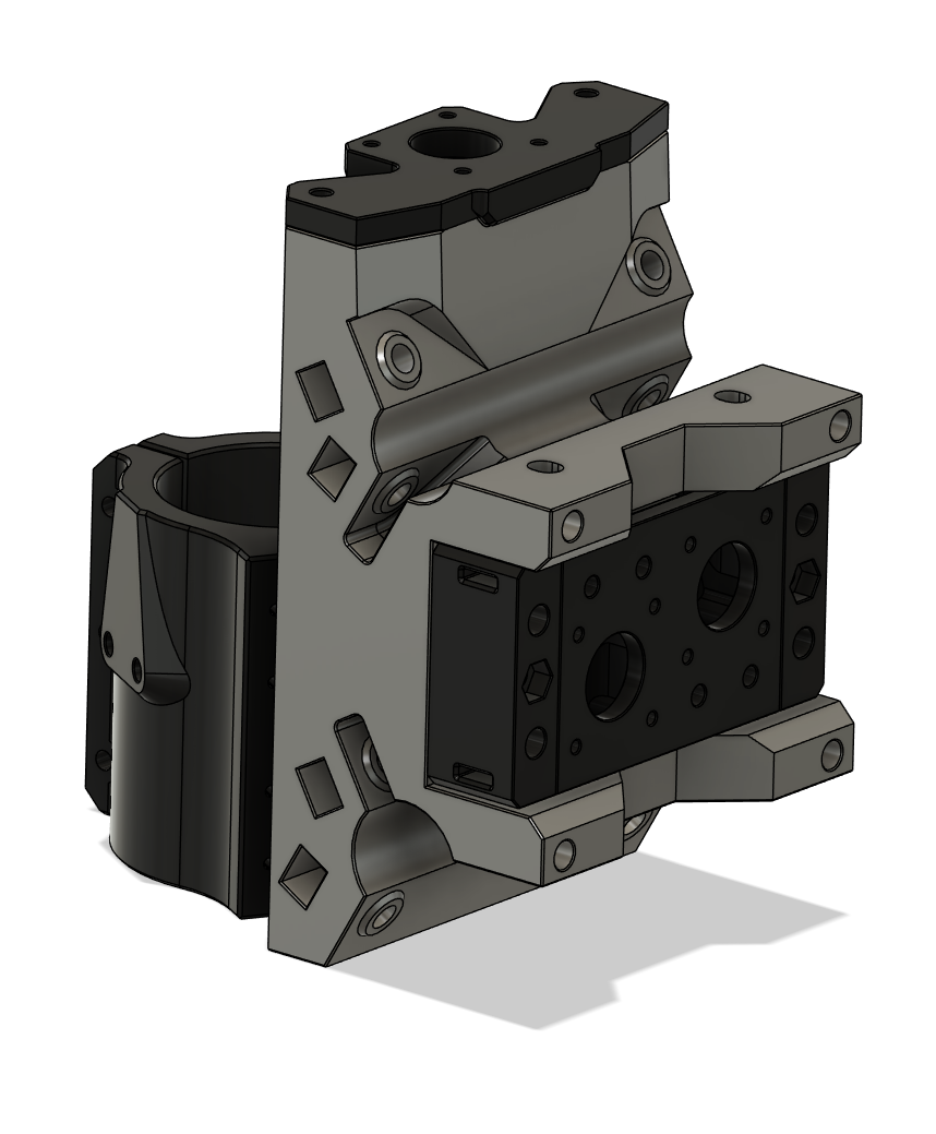
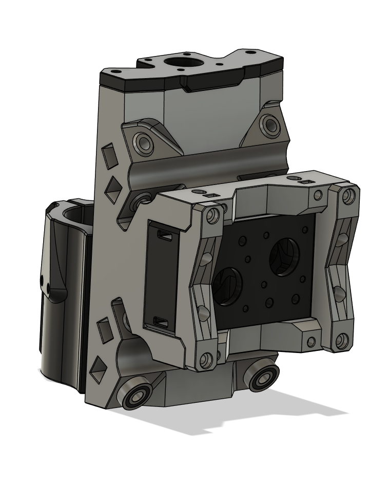
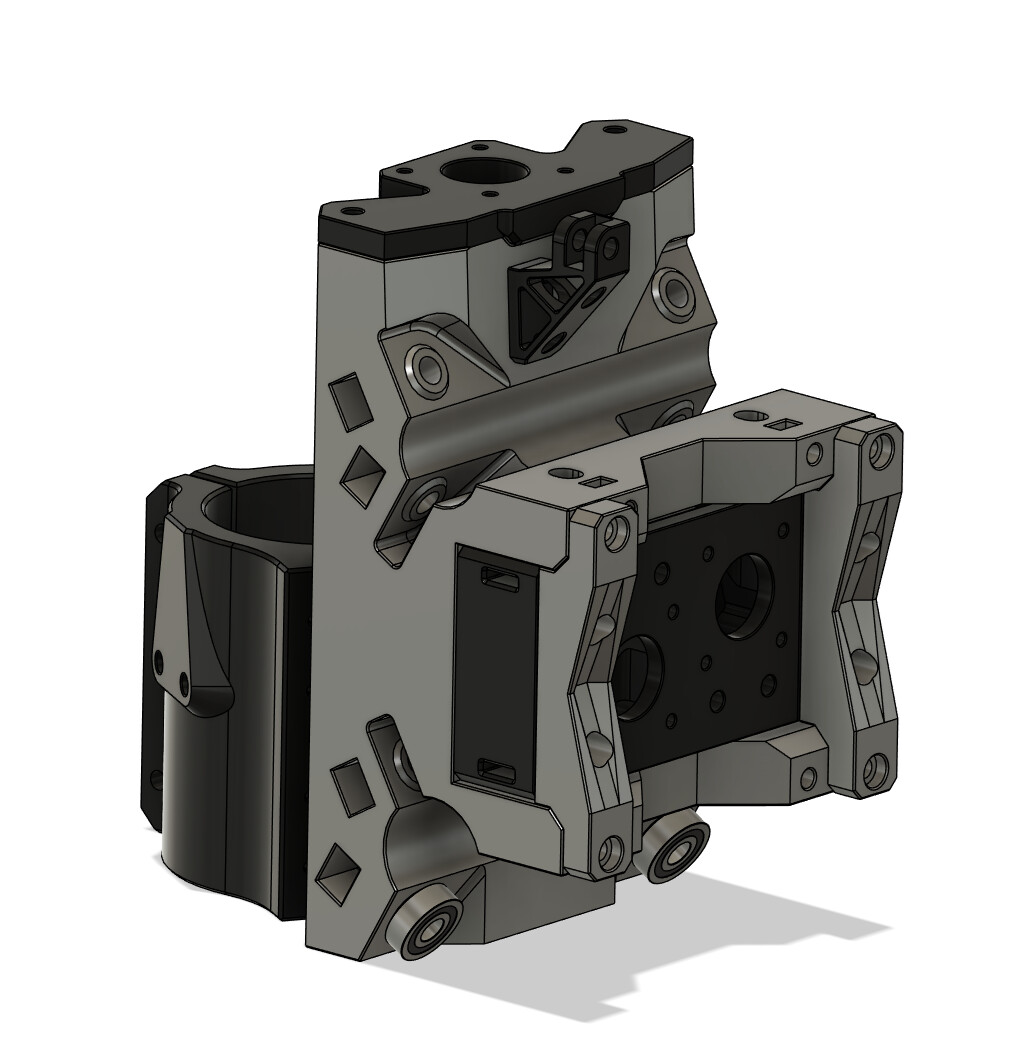
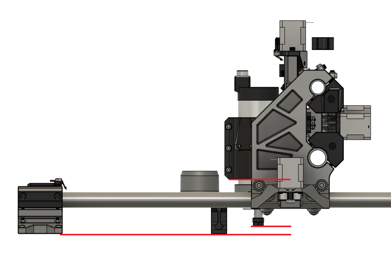
Down to the last thing before I print the parts for my initial testing, the mount for attaching a fixed dust collector. Initial idea is a bracket with a dove tail setup you can attach to but I would love to hear some thoughts on it.
And here are some blank pics if doodles work best for you for explaining:

And lastly, the cable guide mount that took me way too long to figure out one that I liked ![]()
4 Likes
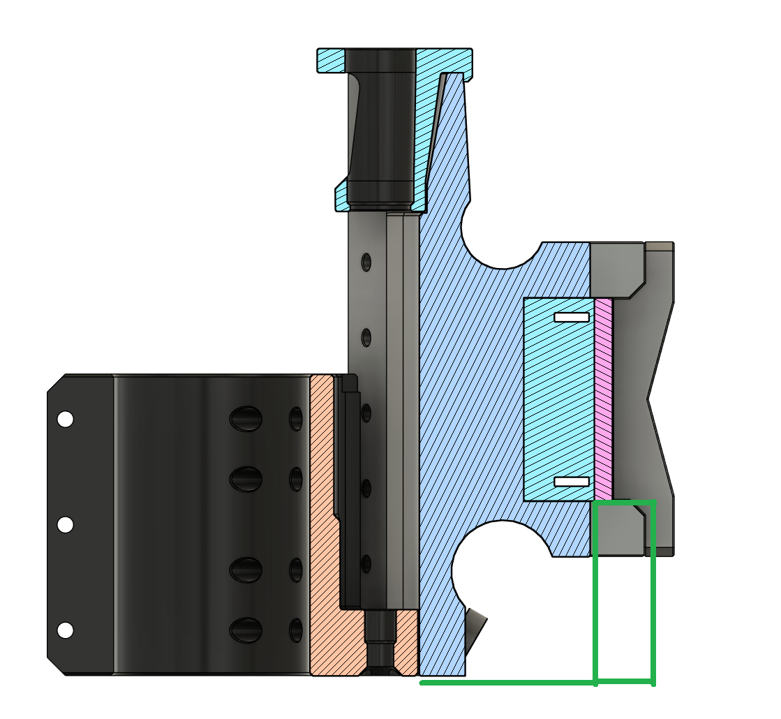
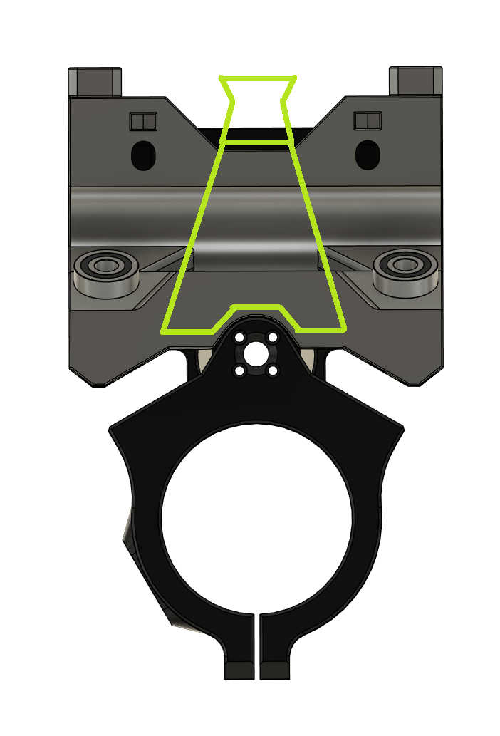
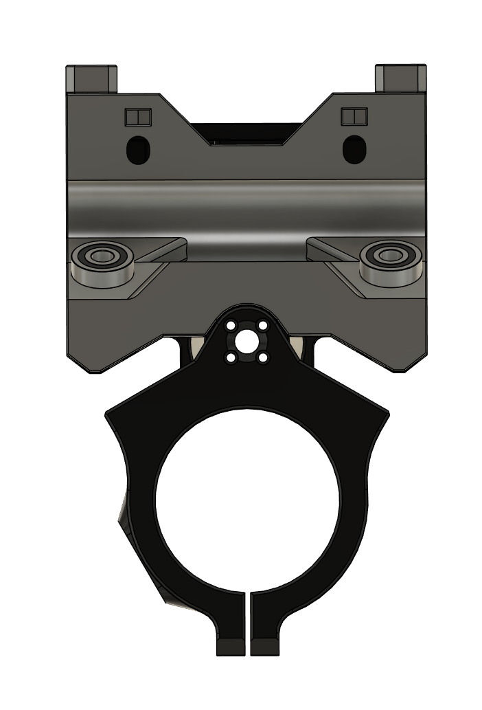
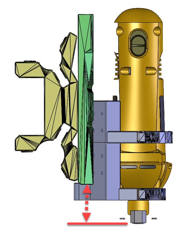
I am working on my build but have not decided to convert to a spindle yet and am trying to use my existing DeWalt DW660. I have started modeling a new mount and am not sure where the chuck should be positioned in the Z. For a spindle it sticks out below the mount clamp. Can’t really do that with this model). Does anyone have a good reference dimension for where the face of the chuck should be relative to say the bottom surface of the left or right rail mount (green)? Below is what I have so far (will print in two pieces and bolt together).
1 Like
Ideally that spacing should be 2.5~3" if working off the plane the bottom of the feet form, gives 1"~.5" of clearance from the collet to the work surface then when at the bottom of the travel. Can reduce it if you bring your work surface above that plane .
1 Like
I’m not 100% sure I’m understanding your thinking regarding the fixed dust collector, but that’s ok. I’ve been using this dust collector that just slips over the Makita so it doesn’t really matter to me (at the moment ![]() ).
).
Once you have things good, I’m hoping you’ll update your Printables entry. My Makita holder has cracked so while I reprint it, I’d like to reprint the new core and another other updated parts.
Thanks.
1 Like
Seconding this, also loving seeing the progress @Brute71! Can’t wait to get to printing.
Hi, I am having some trouble with the Z axis and the lead screw binding up during assembly. I am at page 21 of the instructions where I am assembling the Z Stepper Assembly to the X Carriage. I have the lead screw started in the lead screw nut and when the Z Stepper Assembly is not yet mounted to the X Carriage it all turns pretty easy. However, when I go to mount the Z Stepper Mount onto the top of the X Carriage, the lead screw immediately binds up (even before the screws go in). Is this somewhat normal? There is not much available grip to turn the lead screw so it is hard to tell how bound it really is, but definitely much harder to turn (even at coupler) once the parts are just placed together. I cannot see any clear culprits for mis-alignments. The fit of the Z Stepper Mount to the X Carriage is a bit snug, but does not seem bad or unintentional. The router mount and rails seem to be moving fine prior to assembly as well. And I have lubricated the Lead Screw (Silicone Grease). Any thoughts? Thanks in advance.
Have the lead screw in the nut but out of the z-stepper mount bearing, set the z-stepper mount in place and see if the top is lined up with the bearing. If they arent lined up, either the lead screw is bent, the nut isnt sitting square in the router mount (or isnt machined right), the z-stepper mount isn’t seating against the rail mounts, or the router mount surfaces the linear bearings mount to are just a little to far out pushing the nut out of alignment with the z-stepper mount.
1 Like