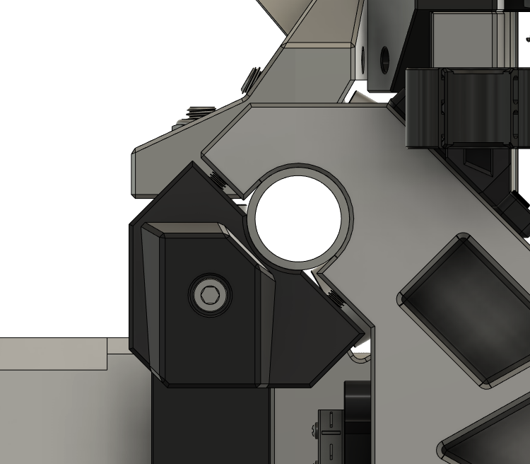
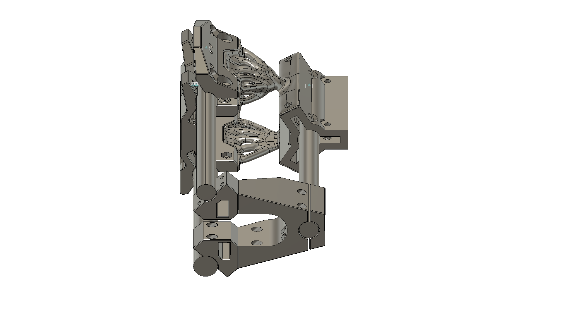
Reworking the mount for a Bosch 1617EVS. Minor deflection while using a 3/8" ball nose bit / 10mm DOC / 2000mm/min. The deflection seemed to be at the linear rail block. I was a bit surprised, but then again I purchased inexpensive rails. Extending the mount height to add two more blocks (4 in total). Maybe that will reduce the deflection. Otherwise I need to look into better linear rails.
You may want to print off that brace I posted earlier too. That is a lot more router and end mill than I originally intended (ball mills tend to have higher cutting forces), curious to hear more about how it is doing with that unit on it.
I was building the gantry right when you posted the brace. It was an easy addition.
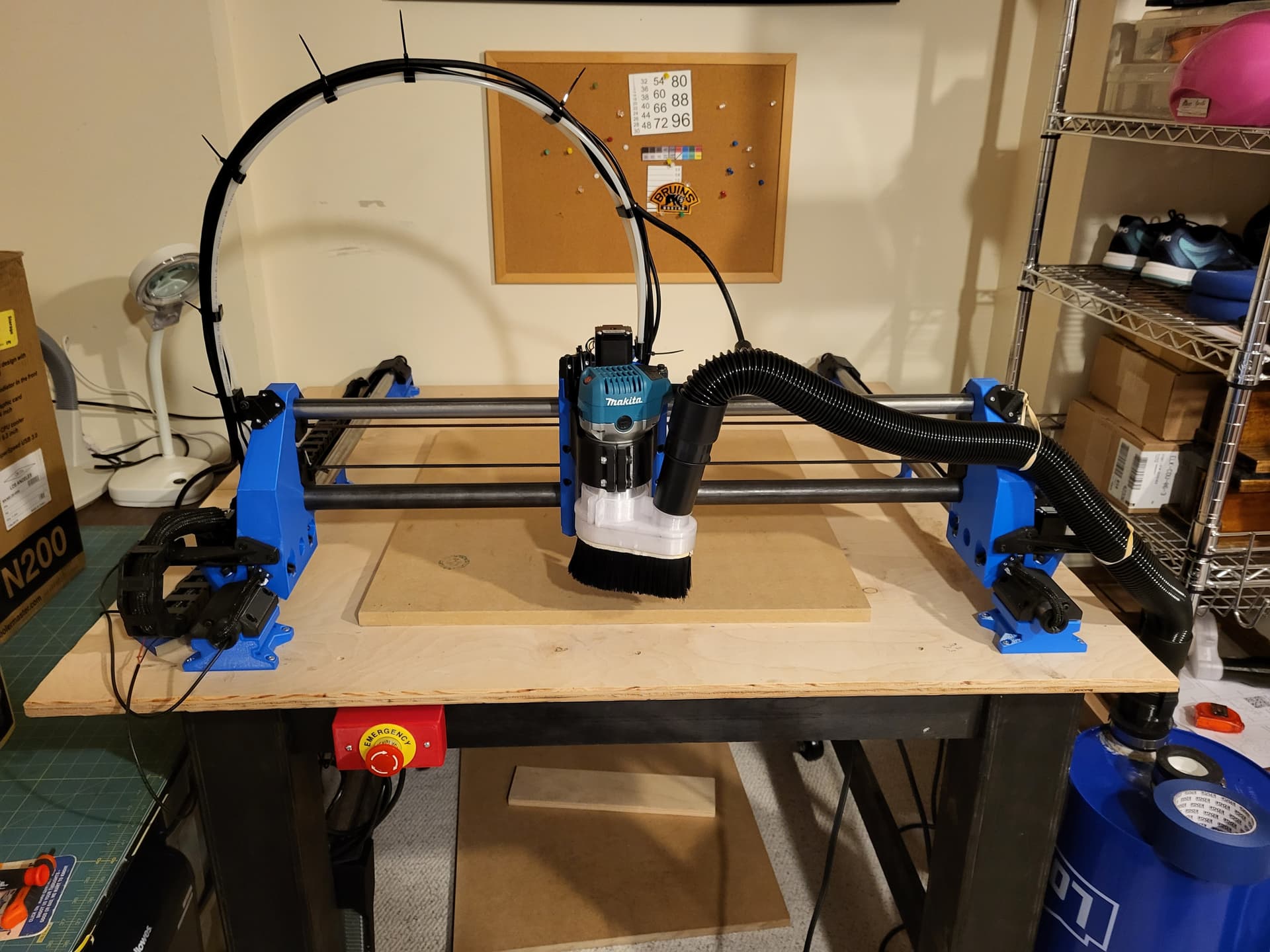
Well, my build is 50" x 150". A bit larger than your intent indeed!
The test cuts I just performed all went quite well. Very few quirks to work through. I might add an additional tube (form a triangle) across the back and somehow make that function as the cable chain guide too. Not a design guru, but I do have fun tinkering in CAD.
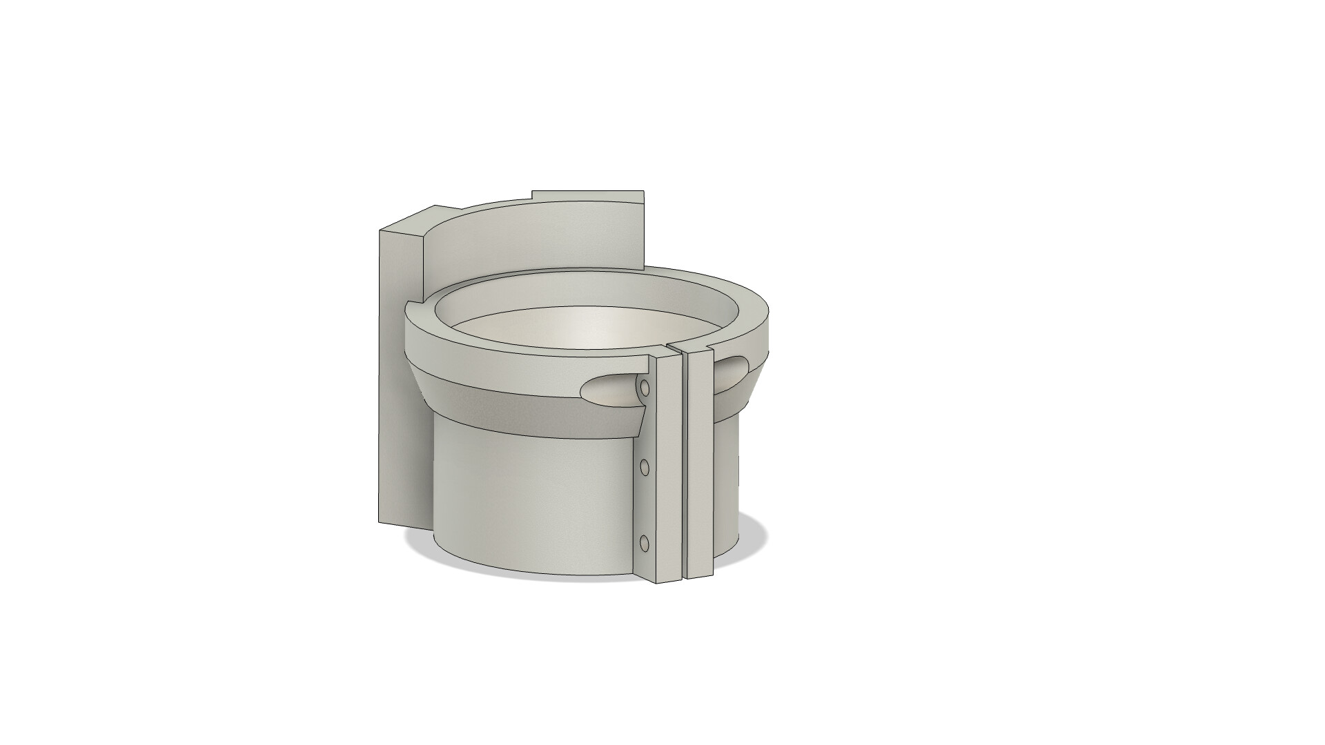
I’ll post a video when I get the vacuum mount situated and functional.
That is a monster size! Bigger than the bench I have my mill and lathe attached on Tinker away! Might help someone else that decides on a machine that size!
That’s how I was taught to terminate them as an apprentice (working on baggage handling systems) We would only terminate at the VFD/Control side, and to leave the shield unterminated at the motor end.
From what I’ve read online, people seem to be saying to earth the VFD shield at both ends. Which throws me a little.
I’m assuming the shield is to be connected to an earth source at the VFD, and the interior earth to be connected to the same point.
On the spindle end it gets a little foggy…3 phase pins and 1 earth pin. Except the earth pin isn’t physically connected to the metal of the spindle.
As I mentioned before, I’ve connected the shield to earth at the VFD/Control, but if the single core earth isn’t connected at the shield and spindle side, I don’t think I’ve earthed the shield at the spindle side.
Time will tell, I may end up joining the shield and earthing conductor at the spindle side, as I’m hoping to use the spindle as a GND reference for my touch plate. I’m thinking I may get some mis-triggers if the VFD is introducing interference - Then again, the spindle won’t be spinning when using the touch plate so maybe it will be fine.
Still making tweaks. But, for the most part it will be nuance from here. 6000 mm/min is as fast as the board will let the CNC go without pausing. There is a bit of chatter at the entry/exit point to work out (amongst other things too).
Question about the new Top X carriage brace, do you still need the two M3x6 that goes into the Z stepper mount assembly (securing the Carriage Cable Guide Mount to it)?
I’m assuming the two M3x6 screws that used to go into the X carriage are no longer needed (they don’t attach the Carriage Cable Guide Mount anymore since it is now removed/replaced with the new Top X carriage brace).
Hi guys, long time lurker first time poster I think. I’ve been running a LR2 for many years and have to take my hat off to V1 for an amazing design and just a great bit of machinery. I’m currently upgrading to the LR3 but have become side-tracked with Brutus. I know this is not a trouble shooting forum for Brutus but I was hoping Alex might be able to clarify a simple one for me.
I’ve printed the left and right gantries as well as the top and bottom caps in metric - the caps don’t appear to have the same radius as the gantries - is this by design? I can’t comprehend how it will be able to secure the horizontal rails - or have I somehow printed the imperial caps with the metric gantries or vice versa?
Sorry for the lengthy first post - honorable mention to Jeffeb3 who without knowing it, has trouble shot so many problems for me over the years.
They should be identical, might not look like it since the cap is supposed to have a gap under it to the gantry side. There is only a .2mm difference in radius between the metric and standard versions.
Sealed up as much as I could, need to seal a bit more…
I’m wondering if I should be sealing the wire entries into the stepper motors. but now I’m also concerned that moisture will get trapped in them from not being sealed - To be honest the coolant is going nowhere near the motors.
The big one is the door - I have coolant leaking out the front, I added a catch to the middle of the door, but I think it might be better placed at the bottom.
Surprised with how quiet this machine is compared to the Lowrider, I guess thats a watercooled spindle?
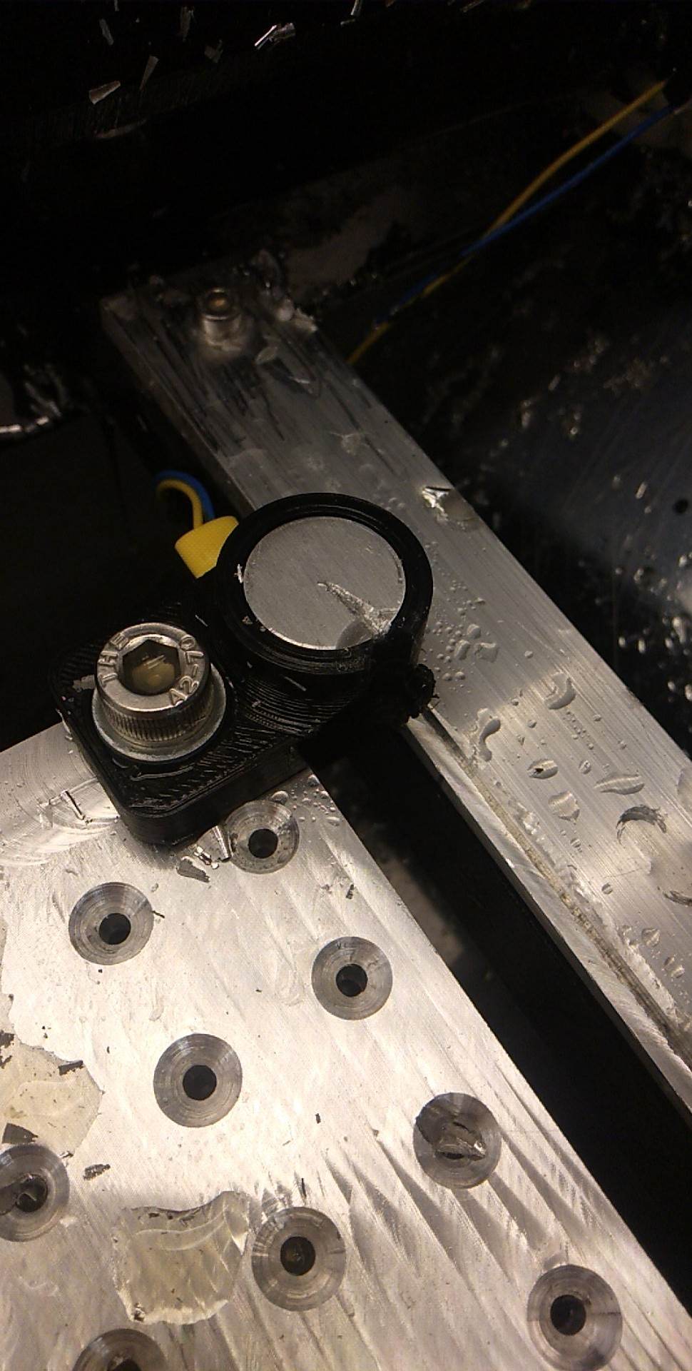
Anyway, I’ve faced the struts where my aluminum fixture plate will be mounted. Hoping to get the plate in the next week (and hopefully that’s the last expense for a wee while)
Pleasantly surprised with how well the straight bit worked (and $25NZD for 4 of them!)
I mucked up the measurements of the struts a wee bit, so can’t face all of them and my cutting area is slightly reduced. Maybe it’s something I will take care of later. at the moment it looks like 205mm*500mm, which I think will be more than enough.
That first pass definitely took a good bite! As for the steppers, as long as where the wires exit are away from the coolant flow or point down, should be fine without sealing. Maybe do a small deflector to prevent the unlikely event of some stray coolant finding its way in there.
I’ll have to go back and reread instructions. I would think if you attached the shield to the ground wire on the motor and then attached the shield to earth ground by the VFD, that the ground wire and the shield would cause a ground-loop. Not sure if that matters in the mechanical world, but if this was audio, that’d be bad
Well, my Brutus isn’t anywhere close to looking like JJWHarris. With the gifts that I gave (no, I mean my wife) gave me, it’s at a point where I can cut. I tried out some insulation foam yesterday and it seems to cut very well ie: 5" = 5". Had to increase the Feed speed since some of the insulation foam was getting melted. Lots of fund and lots to learn and getting the g-code sender set up for bit changes (using a Windows desktop version of CNCjs). Happy Holidays everyone.
 Tinker away! Might help someone else that decides on a machine that size!