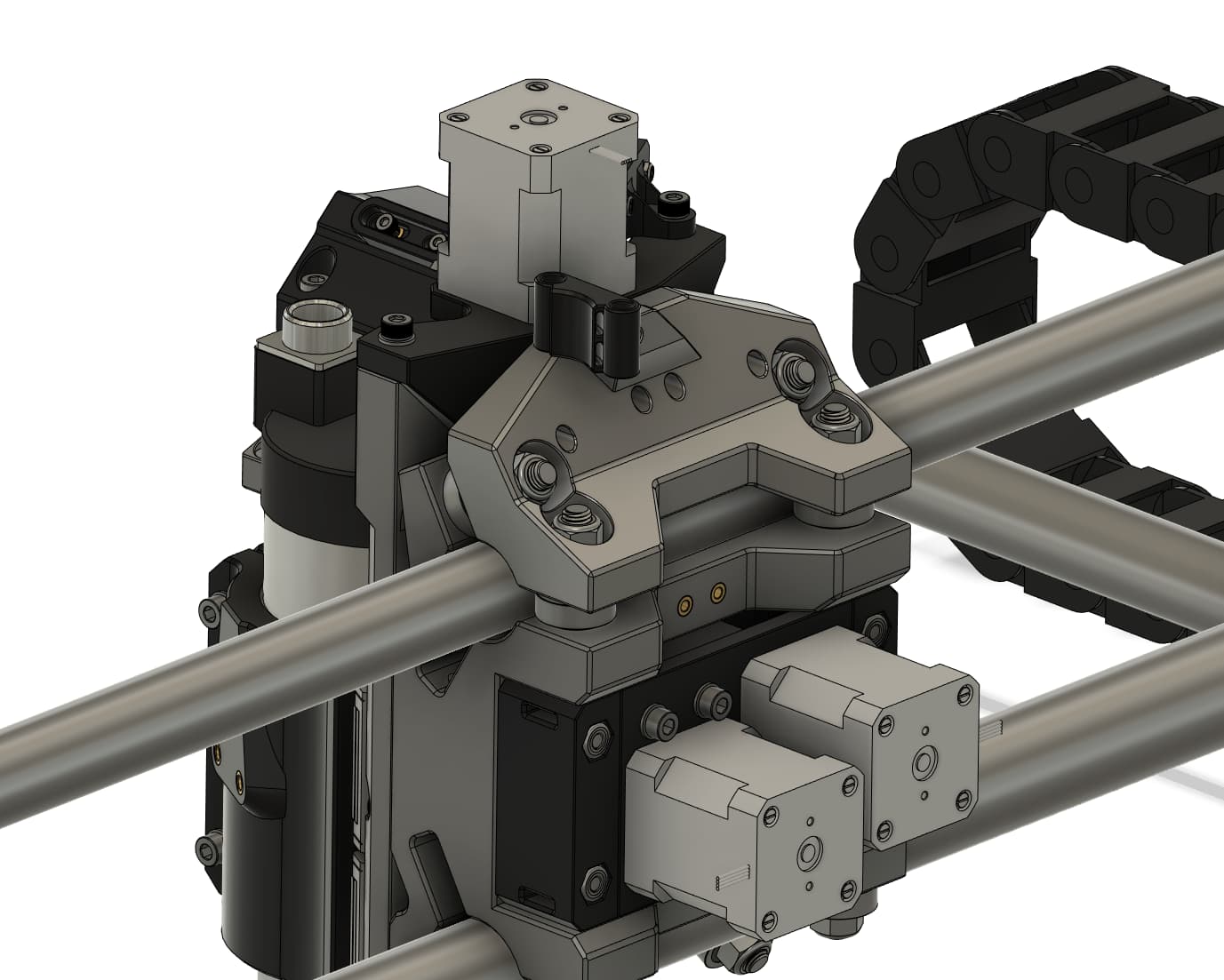
Small part update, added a top x carriage brace to the files, helps address a rigidity issue I came across while pushing it in aluminum. 4 M8X45mm hex head bolts will be needed to install it, I will be working on updating the instructions as I have time.
6 Likes
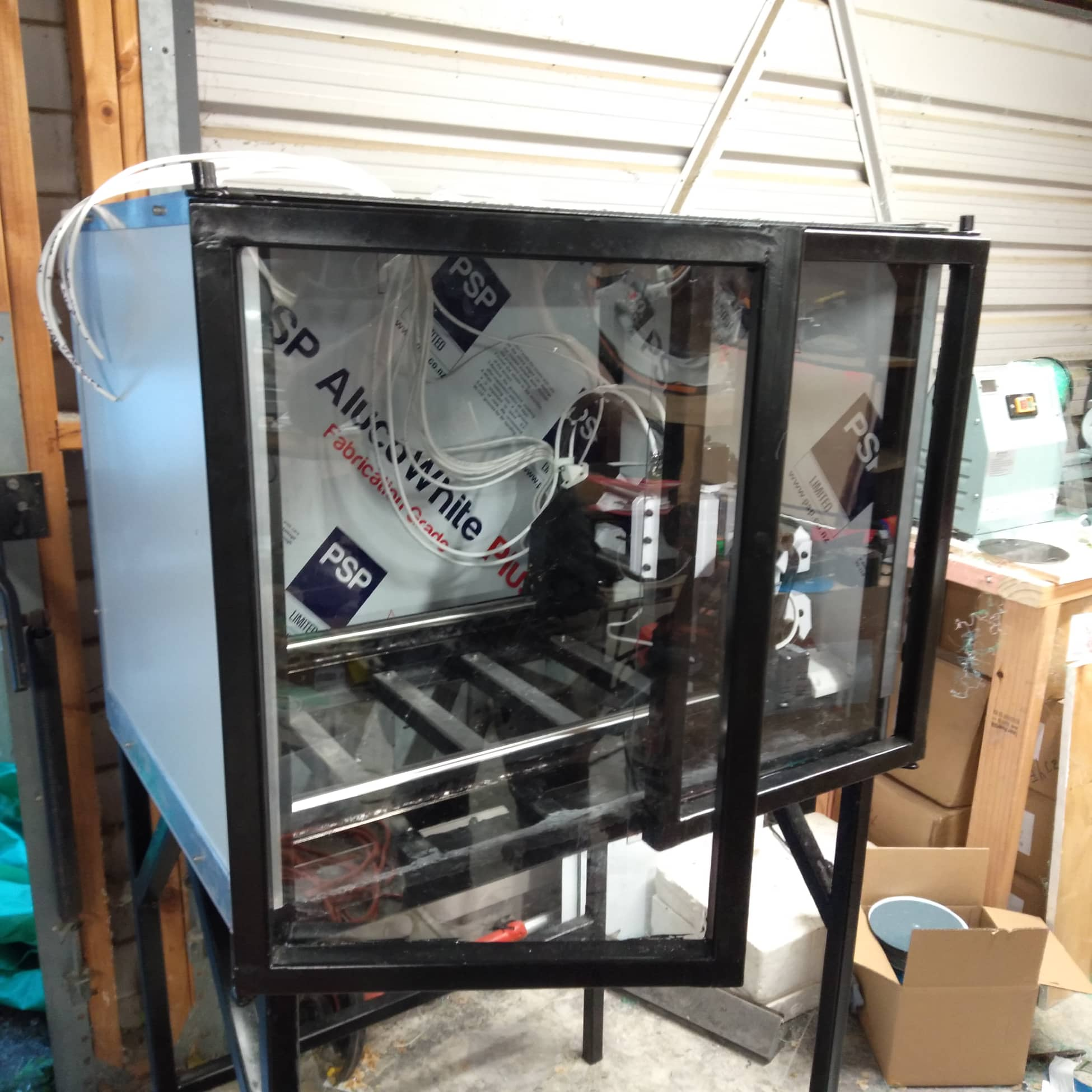
My inserts arrived and it’s all cabled up and mounted. Need to get the real lighting in, but I’m feeling content. I stupidly only ordered rails with 2x MGN12H bearings, when I need 4, so now I’m hoping it’ll be ready for christmas. I need to tidy up the garage and LR3 table so I can cut an enclosure for the electronics.
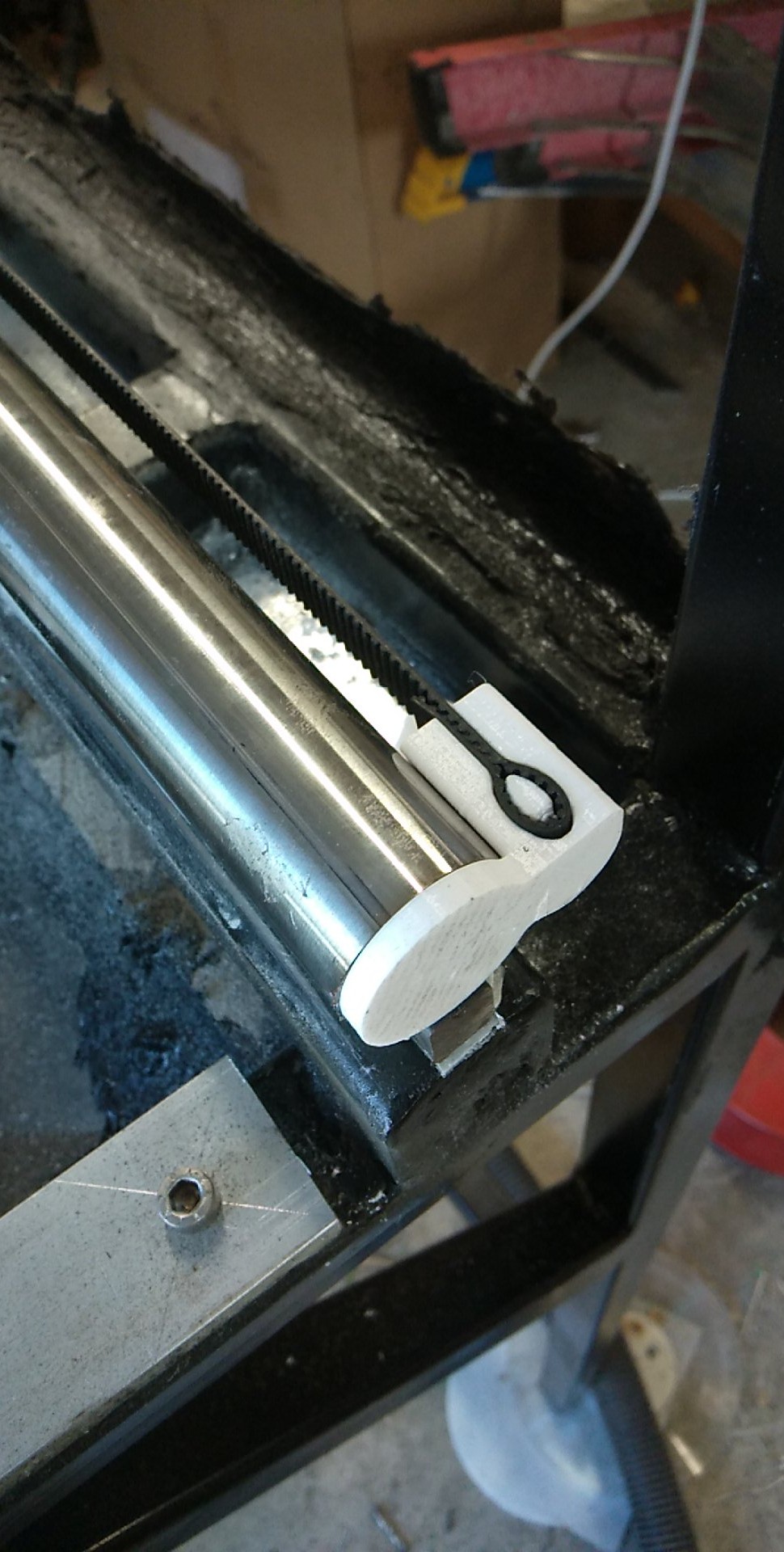
I packed the rails out so they are both in plane (or I hope so!) and then filled in the gaps with epoxy putty. Bit of a stupid move…I think I could have used my fiberglass epoxy bog much more easily.
I would have liked to mount them, below the CNC, but I’m worried about leakage.
So I think I will try to have the liquids below/behind and the electronics on top
I redesigned one side of the belt mounts and made the belt tightening screws accessible from the other side.
I have my coolant pump, and I’m inheriting a spindle pump. Unfortunately I am out of 4C+E cable for the spindle. (Which turns out isn’t actually earthed through the earth pin!)
I’m thinking of mounting a touch probe to the spoil board, having that hooked up to the signal pin, and bridging Earth/Ground to the DC - on the PSU. There seems to be continuity to the end of the spindle. Does anyone know if there are likely to be any issues arising from that?
Hopefully I can dry run it soon, but I’ll be holding off cutting until the bearings show.
I’ll try get hold of some screws for the new mounting part - it looks like it will require some disassembly.
4 Likes
What changes did you make to the firmware to get the single X axis end stop and Z max end stop working correctly?
Slides 52 and 53 of the manual go through all of the changes needed
1 Like
Ahh yep… RTFM
Sorry I haven’t looked at the manual for a while, been spending some time running all the wiring and tidying up the electrical side.
1 Like
I will forgive you if you post some pics of your progress 
1 Like
I’ll hopefully have something new to post tonight…Just wiring up the last of the things.
I’m curious about the V1 manual, it says to not connected the 5V on the limit switches, I have the 5v+GND+Signal line connected on the LR3, and it’s working fine, but I’m wondering if I should disconnect them now…
If the 5v gets closed to ground by the limit switch it can damage the board, the switch has no need for the 5v anyways.
The powered switches need it, we don’t typically use the powered switches.
They should be slightly better, I think they have some noise filtering built in.
1 Like
Ah cool, I thought it may have been that. I’ve had the experience before with a megaboard doing that and it’s never fun.
1 Like
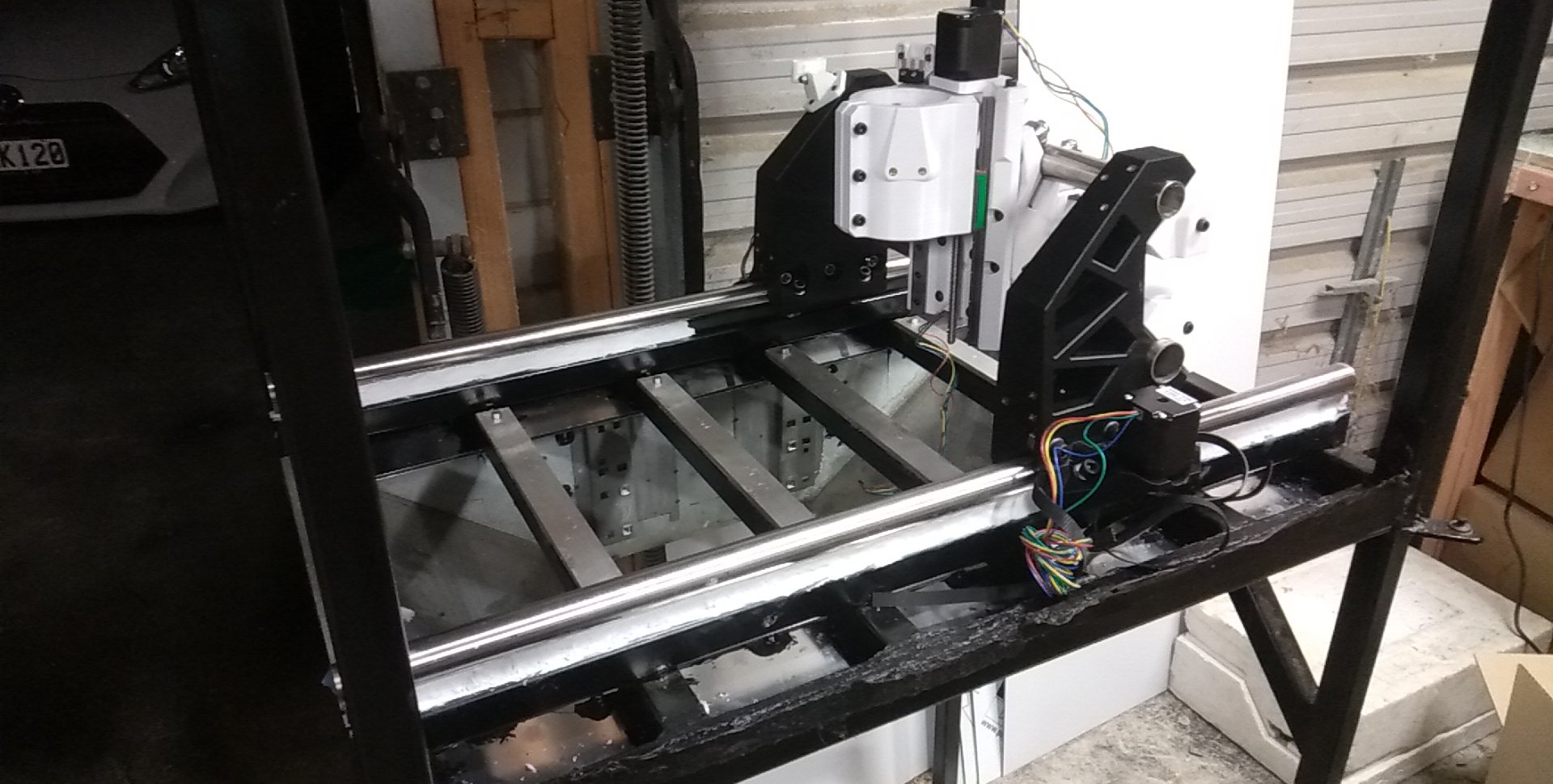
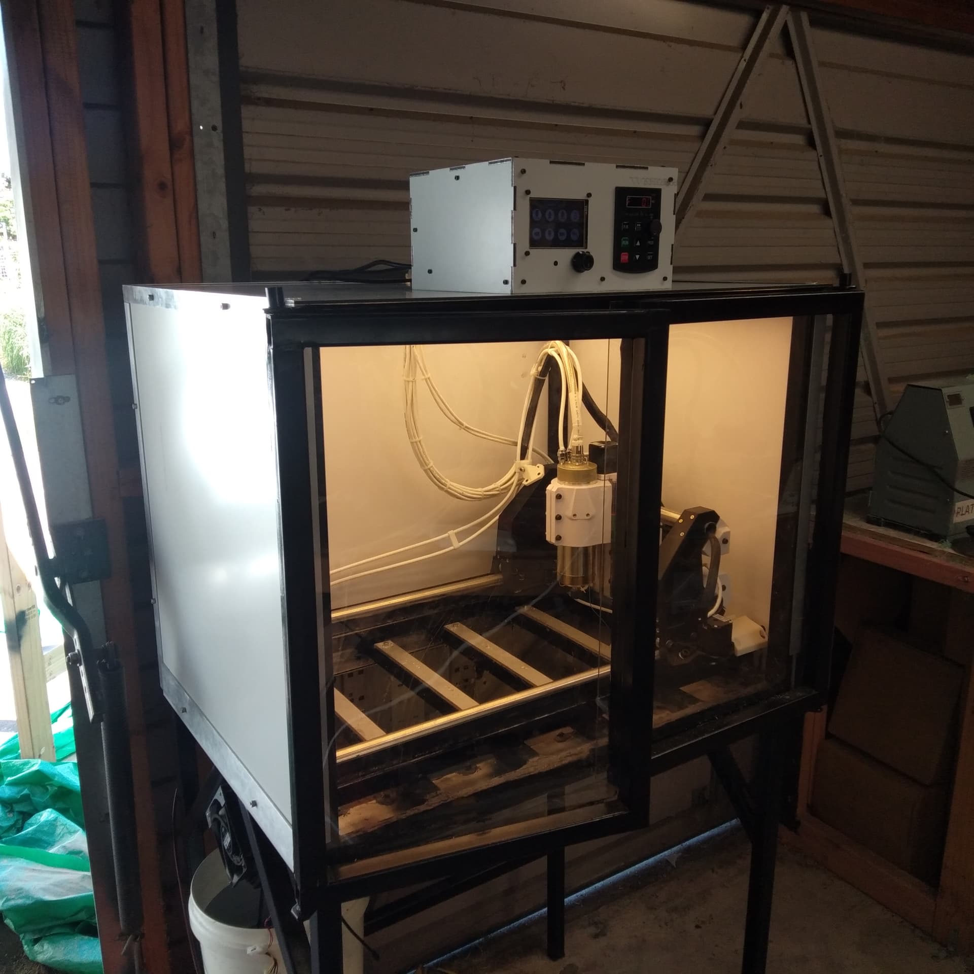
As requested some photos of the machine. It’s pretty much completed. Just have to finish putting all the screws in the feet and do some final calibrations, but our tests so far prove it is a beast if a machine.
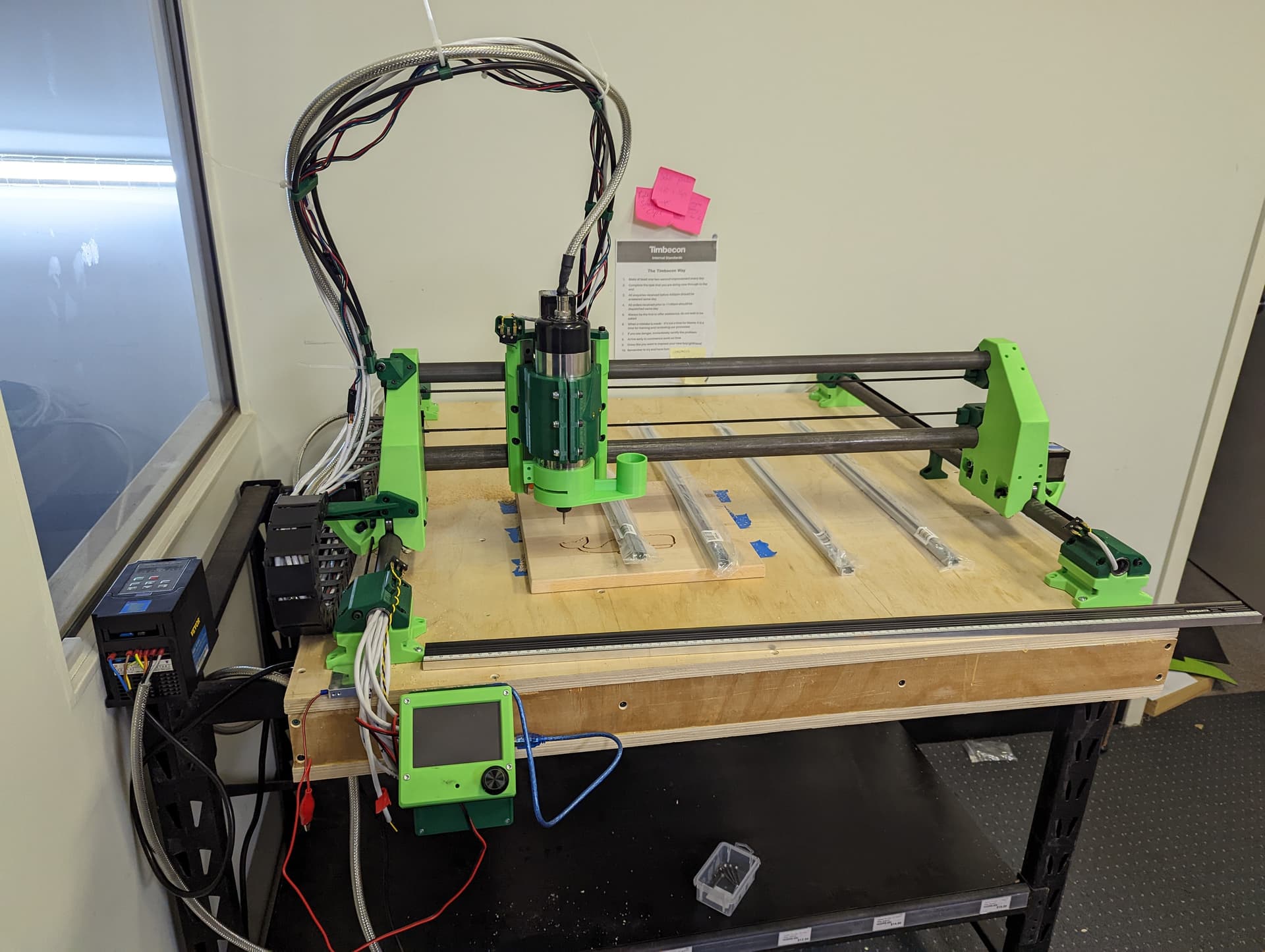
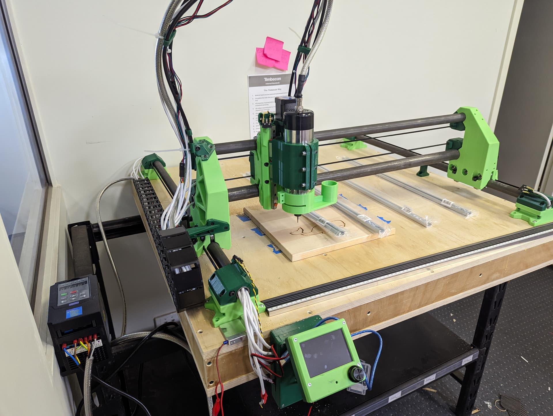
You can see a prototype dust boot installed. Works really well even with our masking tape bristles… Hopefully have that sorted once we find a donor brush.
6 Likes
I’m scared to try cutting anything with the missing bearings, but it’s wired up and moving.
I still need to tune the acceleration and speed limits, but I can’t really see it reaching very high speeds with the relatively small cutting area.
Alex; are there recommended Marlin speeds and accelerations?
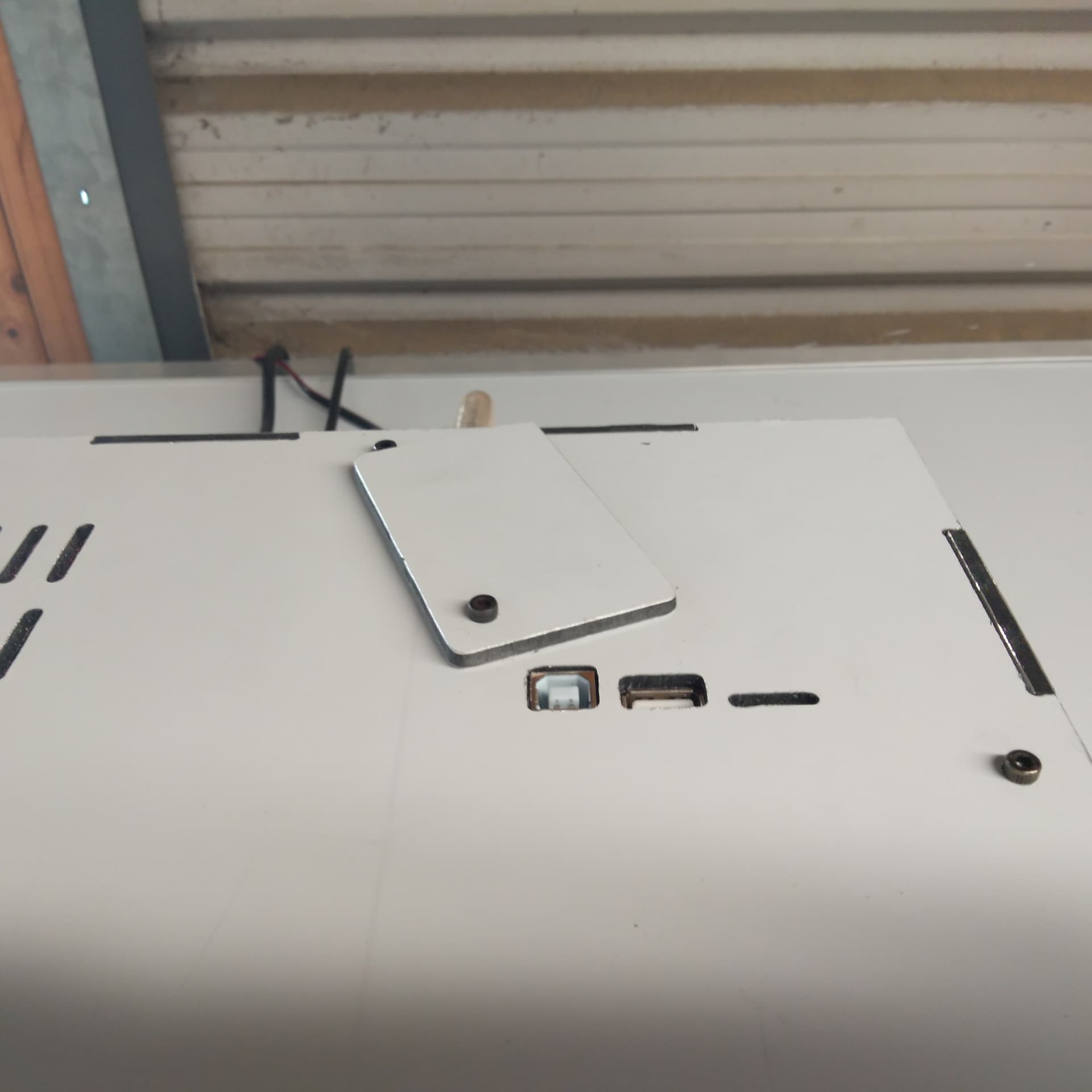
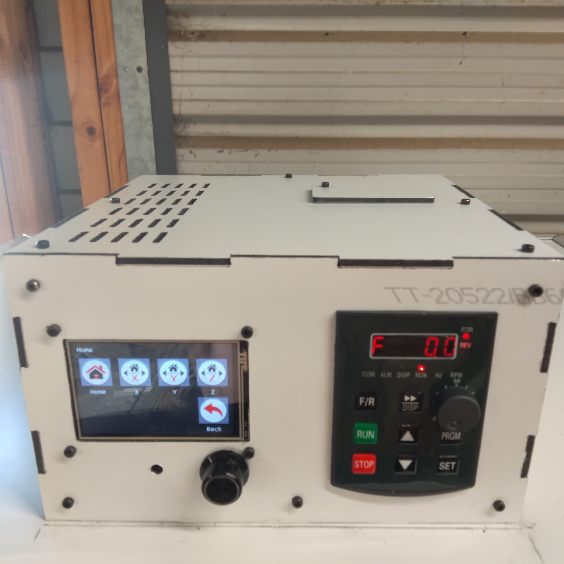
I’ve forgotten to make the SD card slot accessible on the screen, so I might just be running it from repetierhost which is a bit of a bummer.
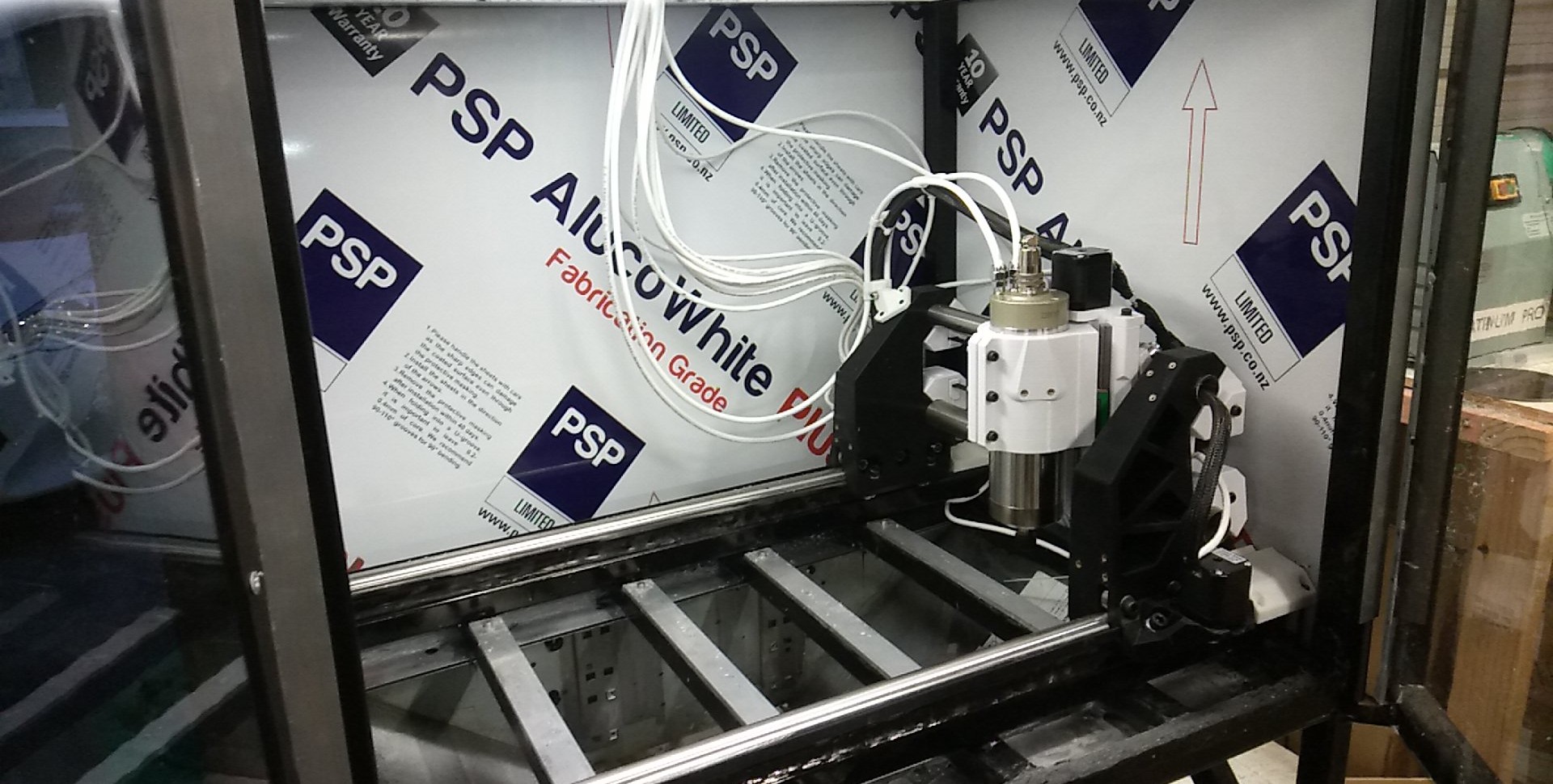
I’ve found the electronics for spindle control from the skr on AliExpress, I’ve wired the cooling pump directly to the VFD so it’s always on when the machine is running…
To be fair there isn’t much reason to have spindle control from the SKR board, the VFD control is easy enough
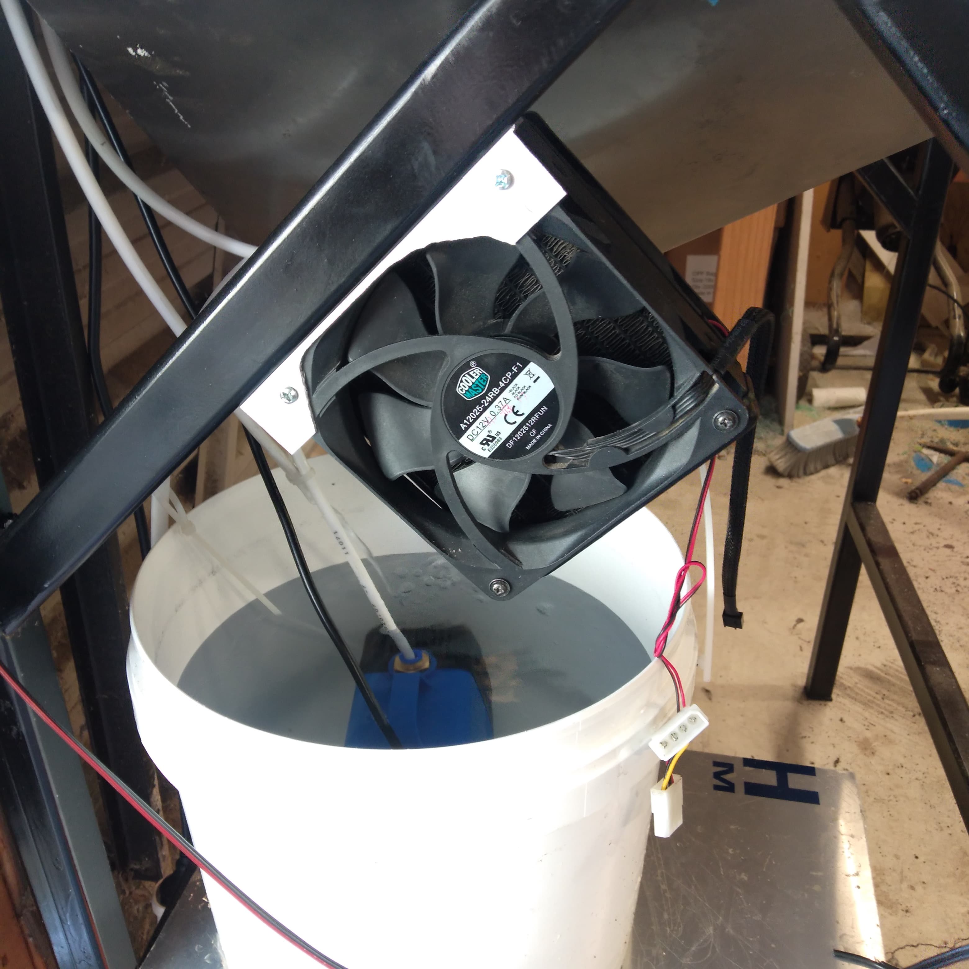
Still need to connect the radiator for the water cooling and make a shelf and grill to hold everything.
It’s a pretty rough and ready setup at the moment
2 Likes
I’ve personally ran up to 800mm/s/s accel, turned back to 500mm/s/s accel on X/Y since my table was rocking at the higher accel, with a 24v PSU I dont see why you couldnt do that 500+ accel rate. So far max cutting speed has been 100mm/s X/Y, personally I have the FW limit at 150mm/s. Very much a ymmv thing since your setup isnt mine (CNC race was 500mm/s/s accel x/y, 100mm/s feed x/y, 30mm/s feed z, my Aluminum speed test I got up to 95mm/s feed x/y). Z speed/accel should be the same as the Primo/Burly/etc since Brutus uses the same lead screw.
I have found just the bristle part of the dust shoes on ebay, can probably find them on amazon as well. Used them for my dust shoe.

After a few goes, I am finding that I am missing steps on the Y axis. I suspect a belt might be a little too loose.
But I was running at 20mm/sec, 5mm DOC and 180mm/sec accel before it started skipping. It was a pine plywood, but I think it was hitting trouble when it got to glue voids. I was doing a linear pocket pass for some rebates. Bit was a 1/4" 3 flute coated with ZrN.
Any ideas where else to look? My steppers are still at stock voltage, I am not sure if it’s worth playing with that as well?
I would recheck the belts regardless after a bit of running as new belts will loosen a bit as they settle in. If your steppers are cool as a cucumber on a fall day, definitely worth playing with the voltage/amperage to get the most out of them.
Turns out it was more than just belts. After partly breaking down the machine, we discovered a number of loose bolts. They were tightened and had a dab of loctite added to prevent them working loose again. Then we developed an issue with the Z- Axis binding, but after adjusting the linear rails, that seems to have resolved itself. Also found a flaky pin on the dupont connecter on the X-Axis and will be fixing that in the morning.
Oh and I also made fire, was testing some speeds and feeds on the plywood sheet that started causing me trouble and quickly discovered the lower limits of mm/sec when it started smoking…
Hopefully once that is done, I can get back to machining things again. It started out great, but after making a couple of mistakes testing feeds and speeds (and one decent crash), I seem to have found a number of gremlins…
Same thing happened with my MPCNC, I ended up rebuilding it from scratch after encountering a whole host of issues (mostly my doing).
3 Likes
Which bolts worked loose? I’ll add a note to use thread lock on them if I haven’t already (I personally thread locked the linear rail screws and linear bearing block screws, don’t remember if I noted that in the manual off hand).
1 Like

Having a good time making this. Excellent instructions. Will disassemble and apply thread locker when tests are done. Everything moves, homes, and works. Decided I must have dust collection before trying it out. I hope my dust collector doesn’t fail miserably. I really, really need to get back to my projects.
2 Likes
I’m glad I’m not the only one using shielded cable…I bought it out of habit working with VFDs as an apprentice, but had to do a bunch of reading up to refresh myself on why/how to connect the shield.
The spindle I bought was a bit of an odd one - had a terminal for what I assume is a safety/protective earth, yet it had no connection to the exposed metal of the spindle, however the shield was connected to exposed metal of the spindle.
How have you terminated your shield?
I use 6-wire shielded cable for motor runs and end stops. The shield at the “motor” end of things is not connected to the frame or spindle in any way. The shield is connected to ground/earth inside the controller case by way of a connection to the ground pin of the mains power jack.
1 Like