Finally got a crown. Used F-Egrave to generate gcode file. The GRBLcrown gcode I downloaded from the Milling Basics docs seems to be incomplete. So here it is…
Finally got a crown. Used F-Egrave to generate gcode file. The GRBLcrown gcode I downloaded from the Milling Basics docs seems to be incomplete. So here it is…
That is making some legitimate robot noises. My grandkids would LOVE it.
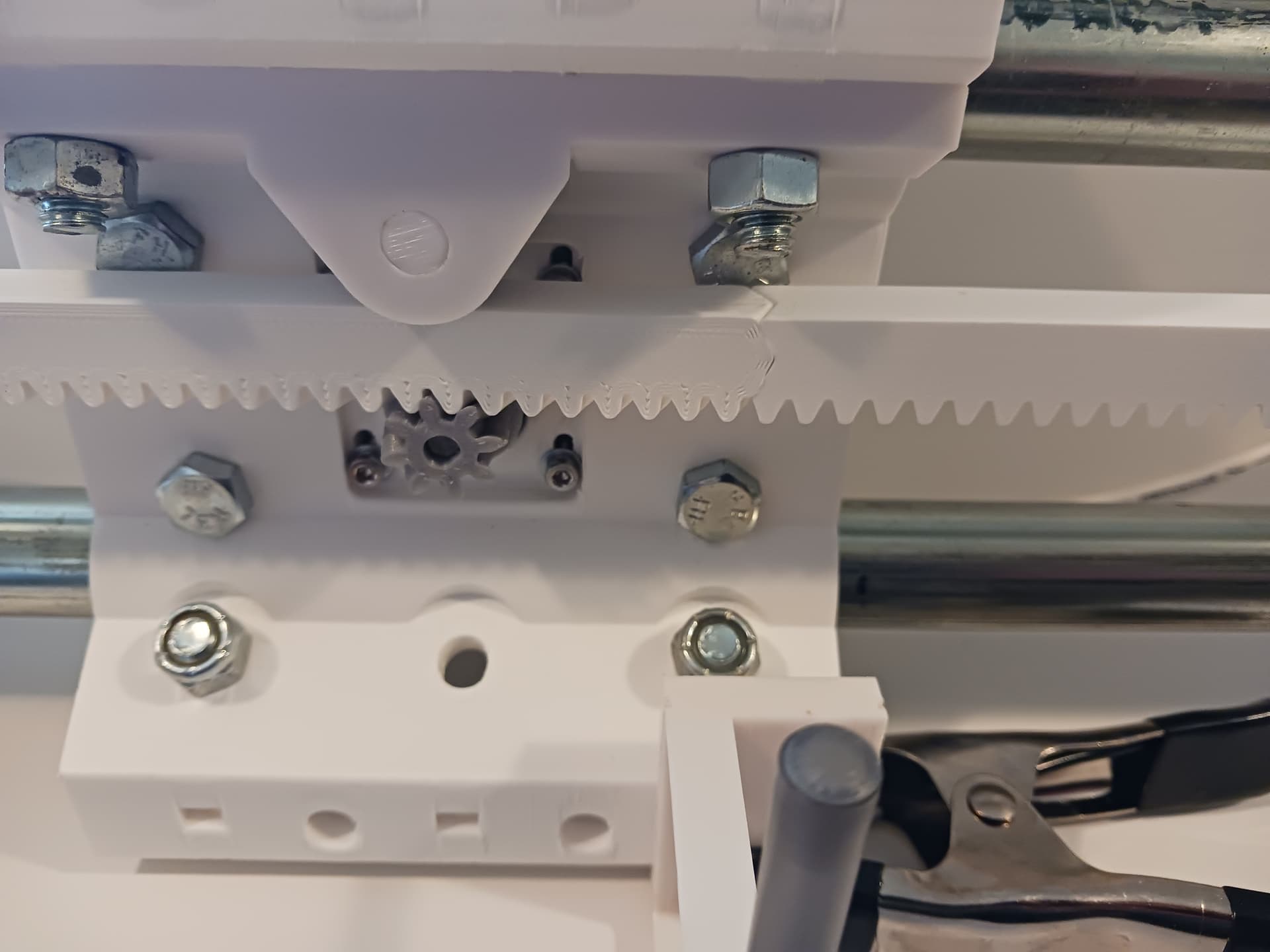
How did I not realize the Y axis had ring and pinion? ![]() All of the parts being the same on all axis is pretty slick.
All of the parts being the same on all axis is pretty slick.
Yeah, modularity was a goal. The original MPR&P had these linear stages but ultimately a different gantry… and more unique parts. When @MakerJim and I started talking about “what if we put a LR4 beam and lift setup on the MPR&P Y-axis linear stages”… it actually simplified the gantry and made for fewer unique parts required.
It initially “tarnished” the idea of R&P on all three axis (which was an original goal)… but I was never really happy with the R&P Z-axis on the original MPR&P anyway. I like the modularity of V2 better… even if the Z-axis is leadscrew driven. LR4’s beam and lift setup and reputation for rigidity swayed my thinking.
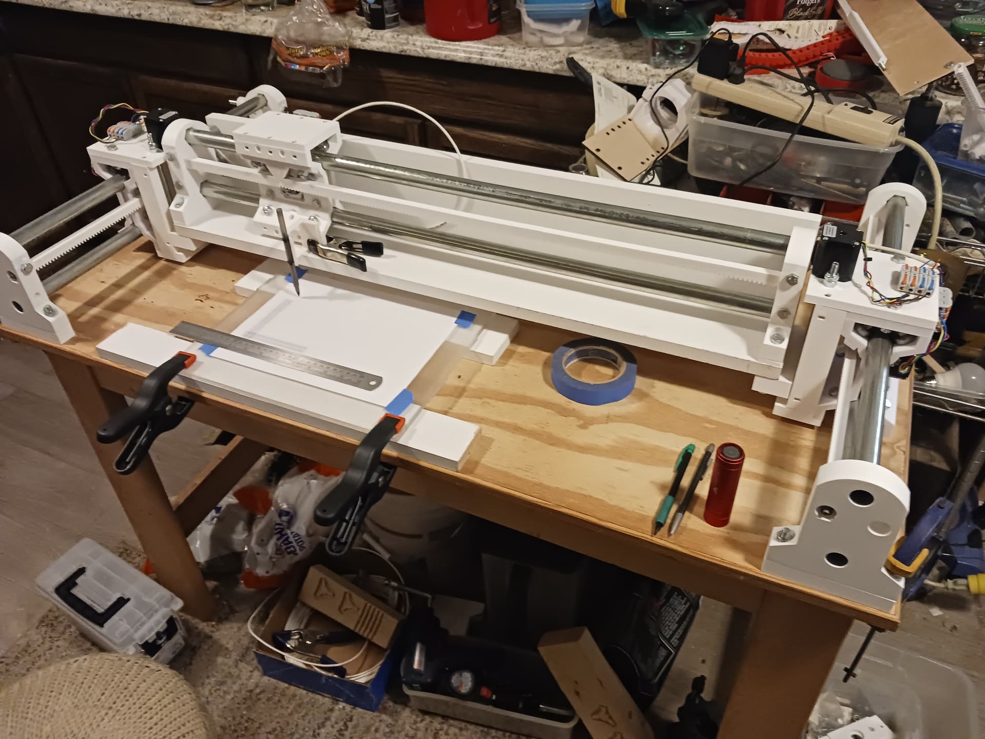
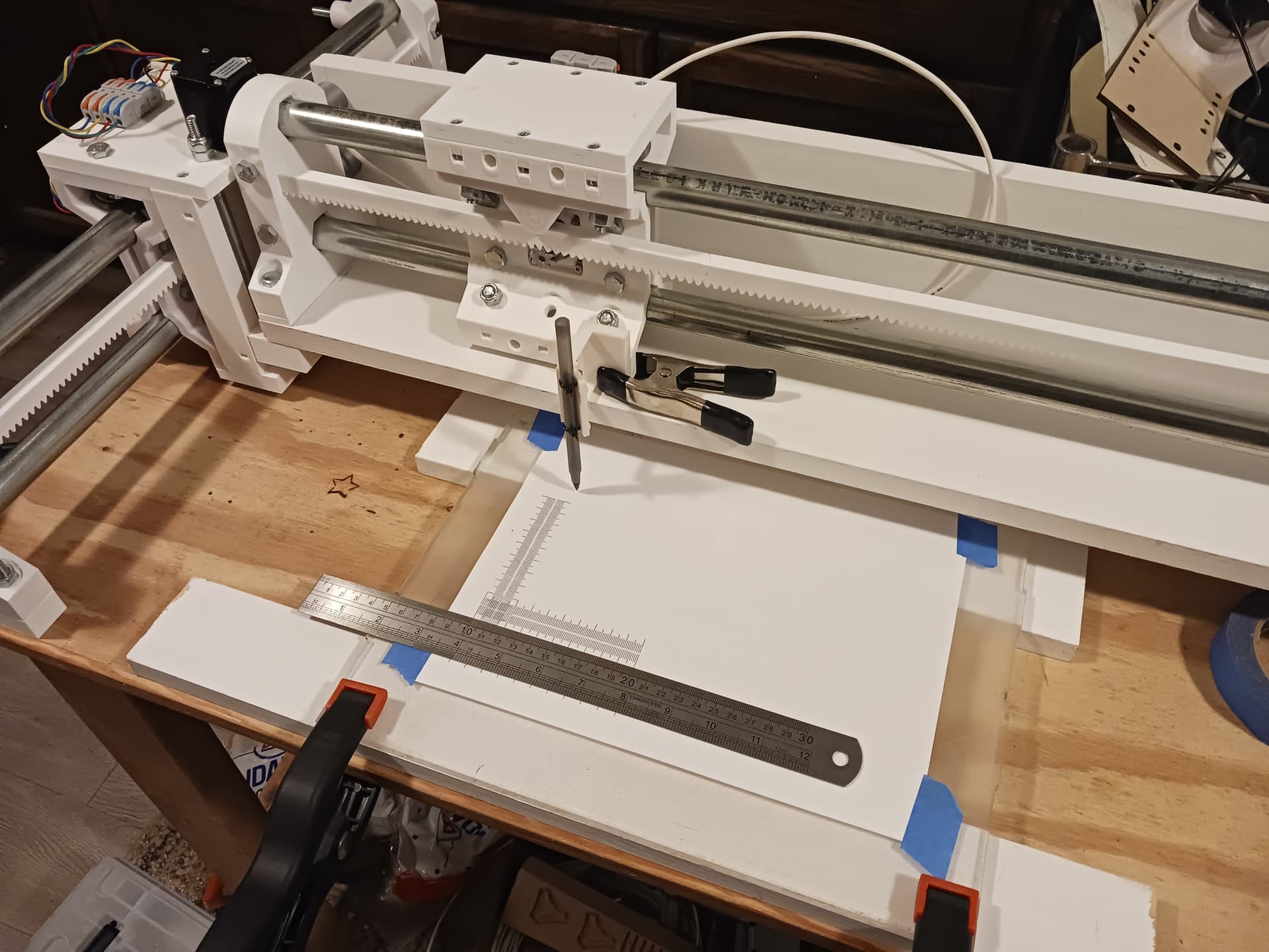
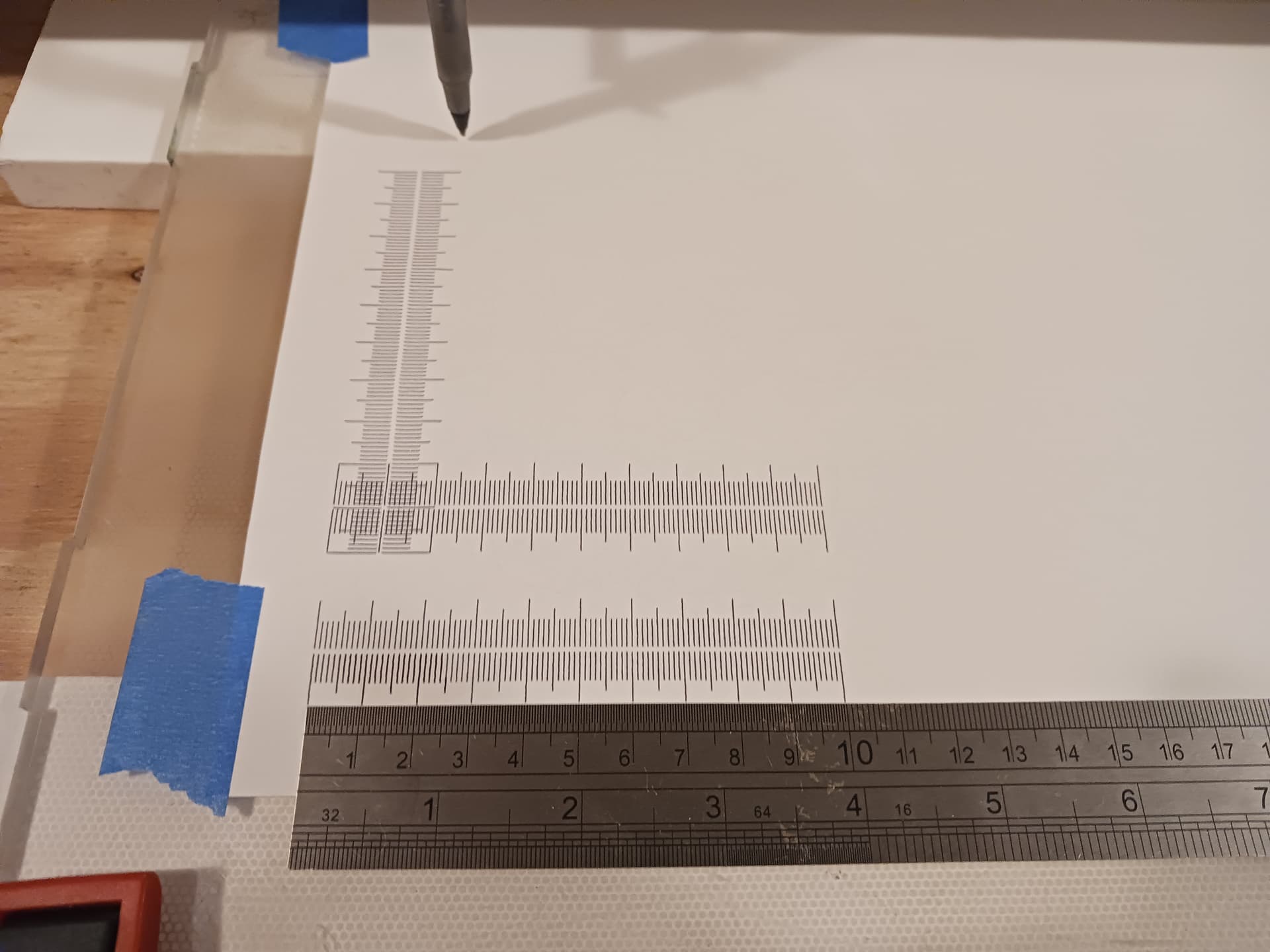
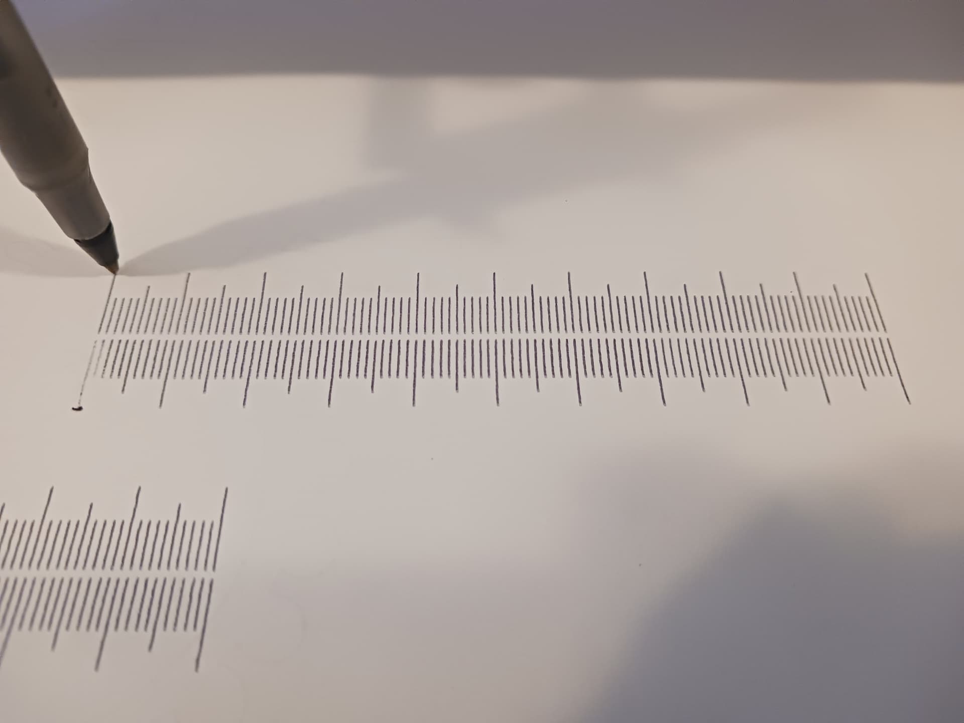
Benchmarking with Jamie’s rulers…
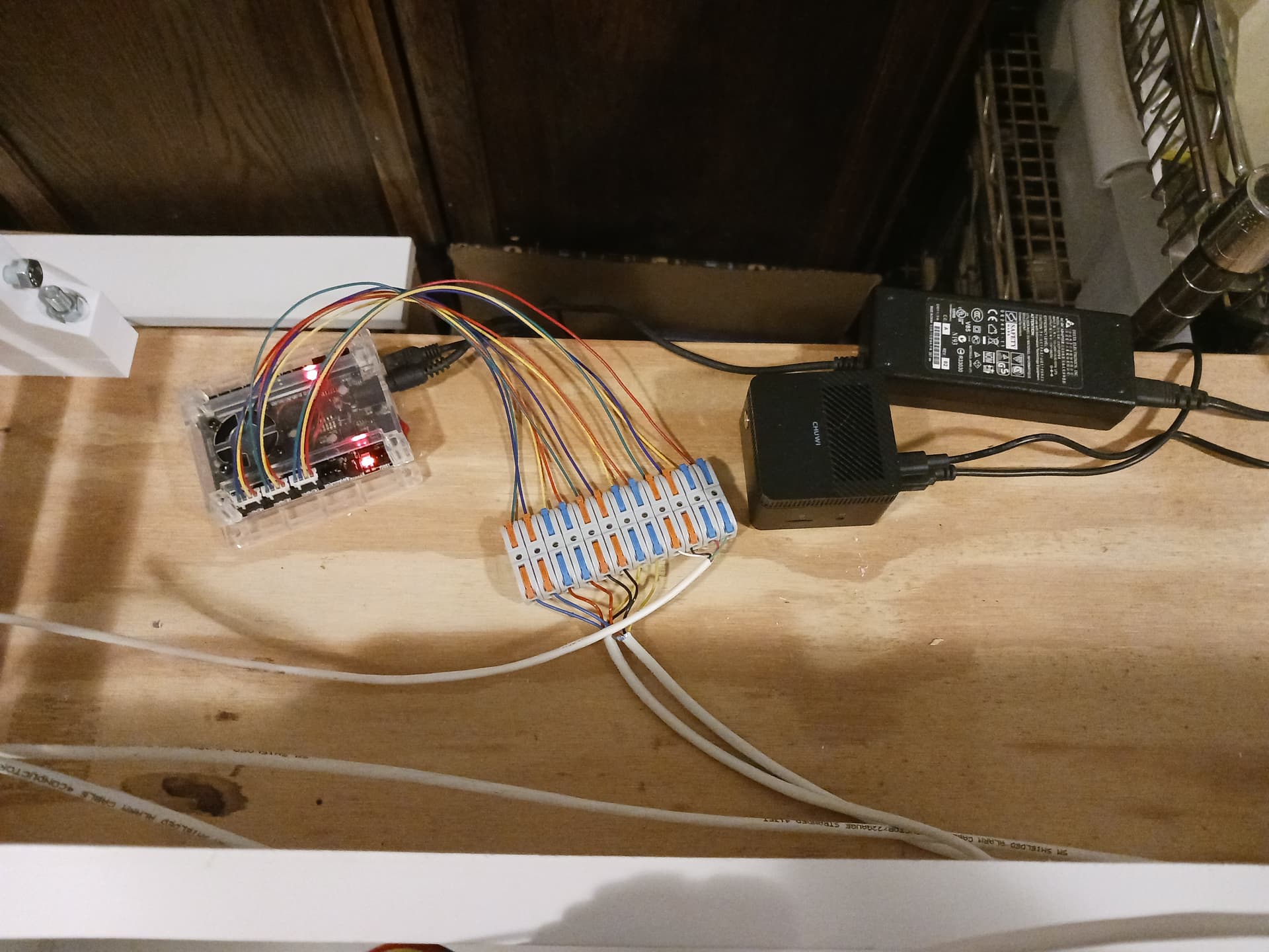
Larkbox Pro miniPC running Jamie’s test pattern gcode in UGS and connected to inexpensive GRBL controller through USB. Y and Z motors are series-connected and it’s all running on 12 volts…
MPR&P-V2!
Printed rulers with commercial metal ruler…
Pretty pleased with the way this machine has come together… I’m really starting to like it. I don’t know what a threshing machine sounds like but this surely must sound like one… and it’s interesting to hear what sound each axis contributes to the mix.
Later.
This. Me too.
So impressive. Amazing.
Right proper robot noises.
What a great refinement of the MPR&P.
Looks like it is just about ready for publishing?
That is fantastic.
I’m curious, at the seam between the rack segments, if there is any discernable anomaly in the ruler. Theoretically there could be print defects that affect the length at the butt joint but they might not manifest in your instance.
Are you talking about putting it out on Printables? That’s on the agenda for – hopefully – sometime today.
In that second ruler test video above, it looks like the 100mm mark stopped just short of a rack seam. I have all that set up still… should be able to move the origin slightly right and print another ruler that has to cross the rack seam. Should be able to do that today as well…
Thanks, guys, for all the kind words, encouragement, and ideas for further testing.
This has truly been a fun project. I’m printing a tool plate right now and should be able to show a router mounted on it soon… though I’ll not try to do any cutting today.
Later.
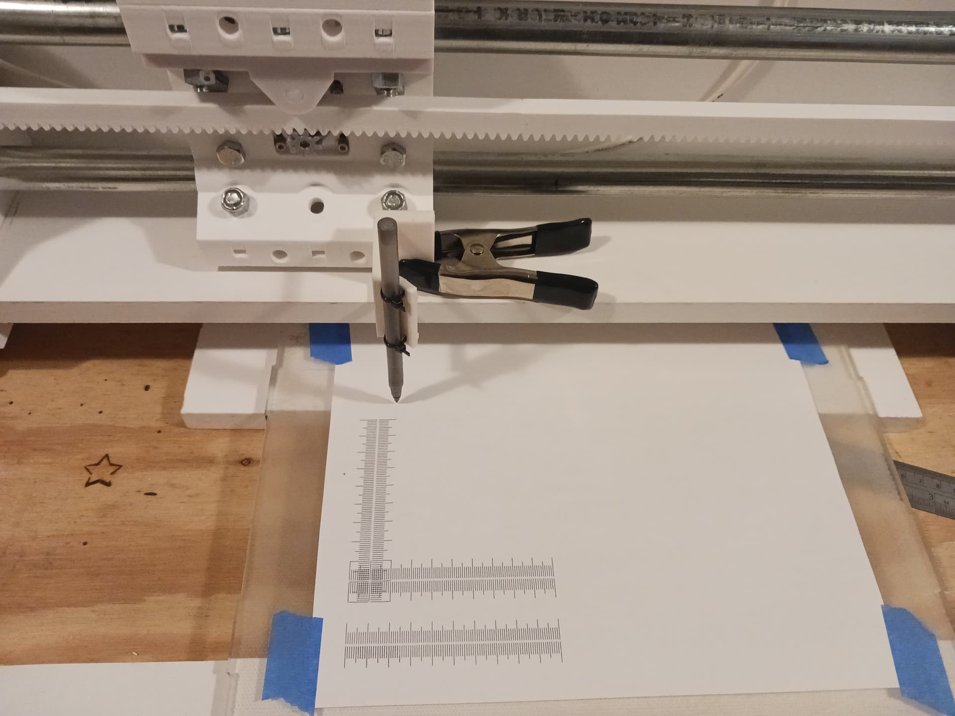
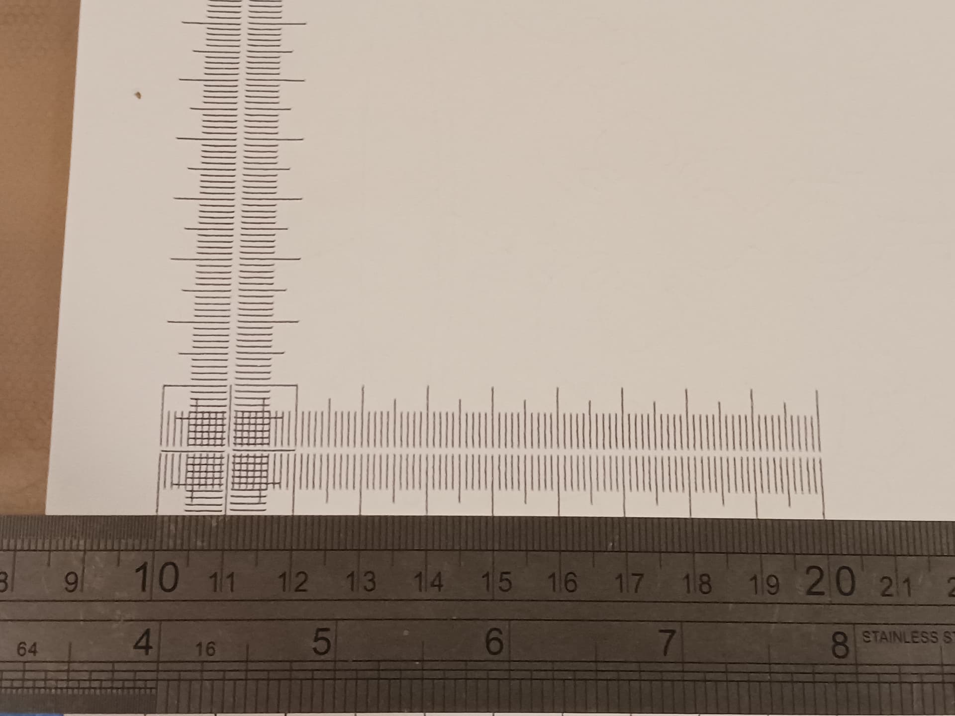
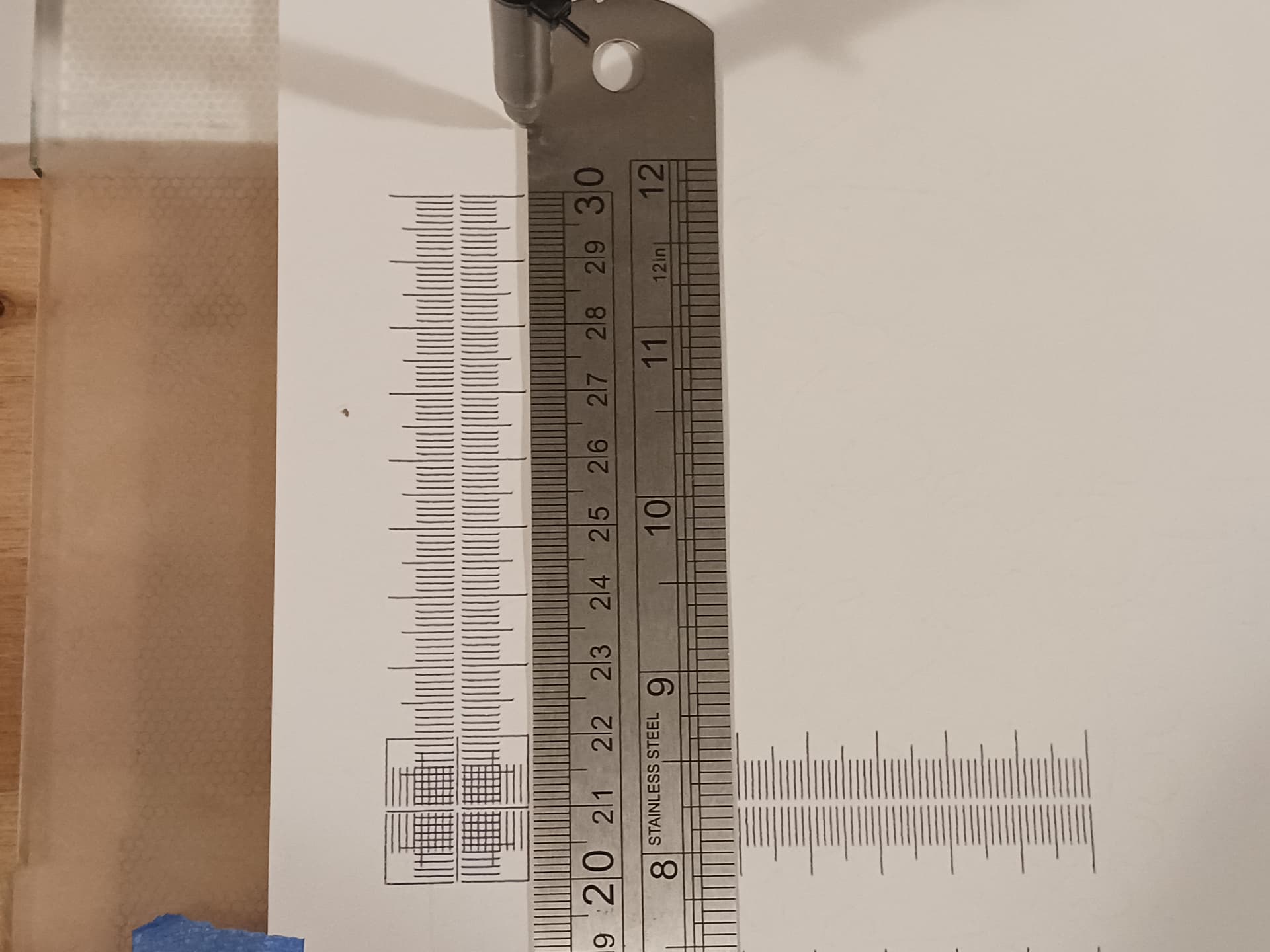
Here’s a 100mm ruler plotted while running across a seam on the X-axis rack…
Shown here is the pinion about 8-9 teeth from the seam at the ruler start position… and a little over 5mm (actually 5.236 mm) between teeth.
Any seam-related anomaly should show up somewhere between 40 and 50mm…
See anything?
![]()
Looks perfect to me. Anything about 0.1 mm or maybe 0.05 mm would show up for sure.
Love that ruler test
I do, too. Thank @jamiek for that!!!
I’m calling it good for a first cut. I think this is pretty complete but is still obviously subject to change…
I’ve omitted the bottom and side panels/boards/stiffeners since they are probably not gonna be printed and are cut to length to accommodate whatever the dimensions for desired footprint or work area. I suppose I could/should provide printable jigs to help locate holes relative to the ends of those panels… it’s difficult to match-drill through wide plastic parts that are probably already bolted in place. Also, with the round spacers and holes through the end supports I’ve thrown in, the side plates could be extended all the way down to form a debris wall on any/all sides.
Please “holler up” if you see something I’ve missed or have questions.
I appreciate all the kind words, encouragement, comments, and ideas that have been shared… not only for this project but for the entire time I’ve been a part of this forum. You are a fun bunch of folks to be around and as I’ve said before… this is “home” for me. Y’all are by far some of my finest friends… even though in most cases we’ve never met face-to-face. Funny how that works! ![]()
Have fun!
– David
First thanks for posting this, its really interesting. Couple of questions:
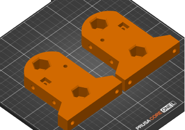
The files named ‘Carriage-V12 - Y-end_support-right’ and ‘left’
Thanks again for this - I’m printing a rack piece now.
What would be the maximum build size?
Yes, the same end-supports – left and right – are used on all linear stages.
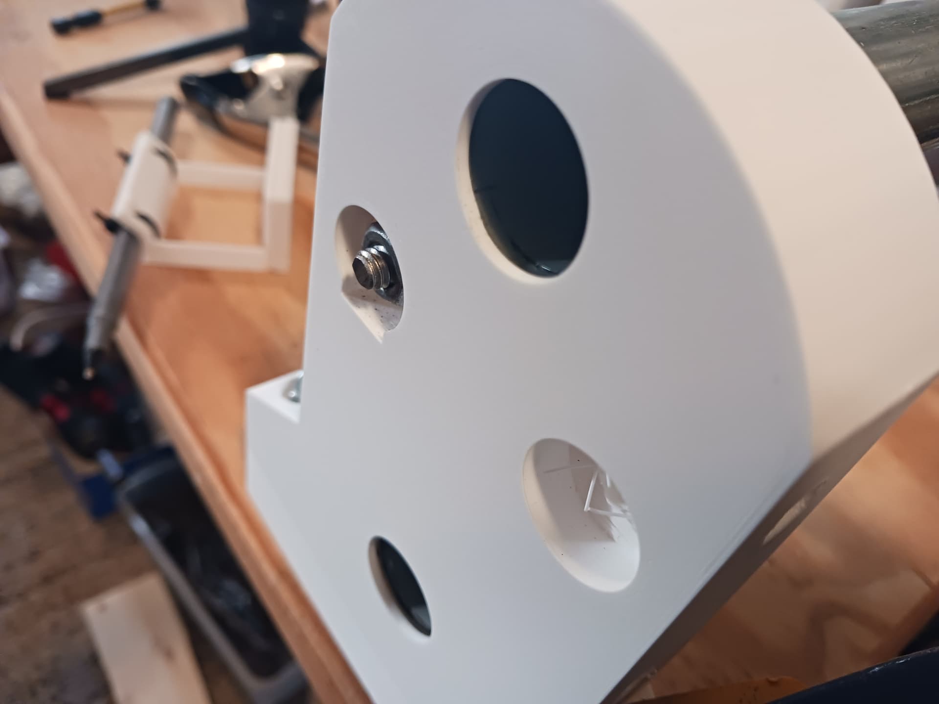
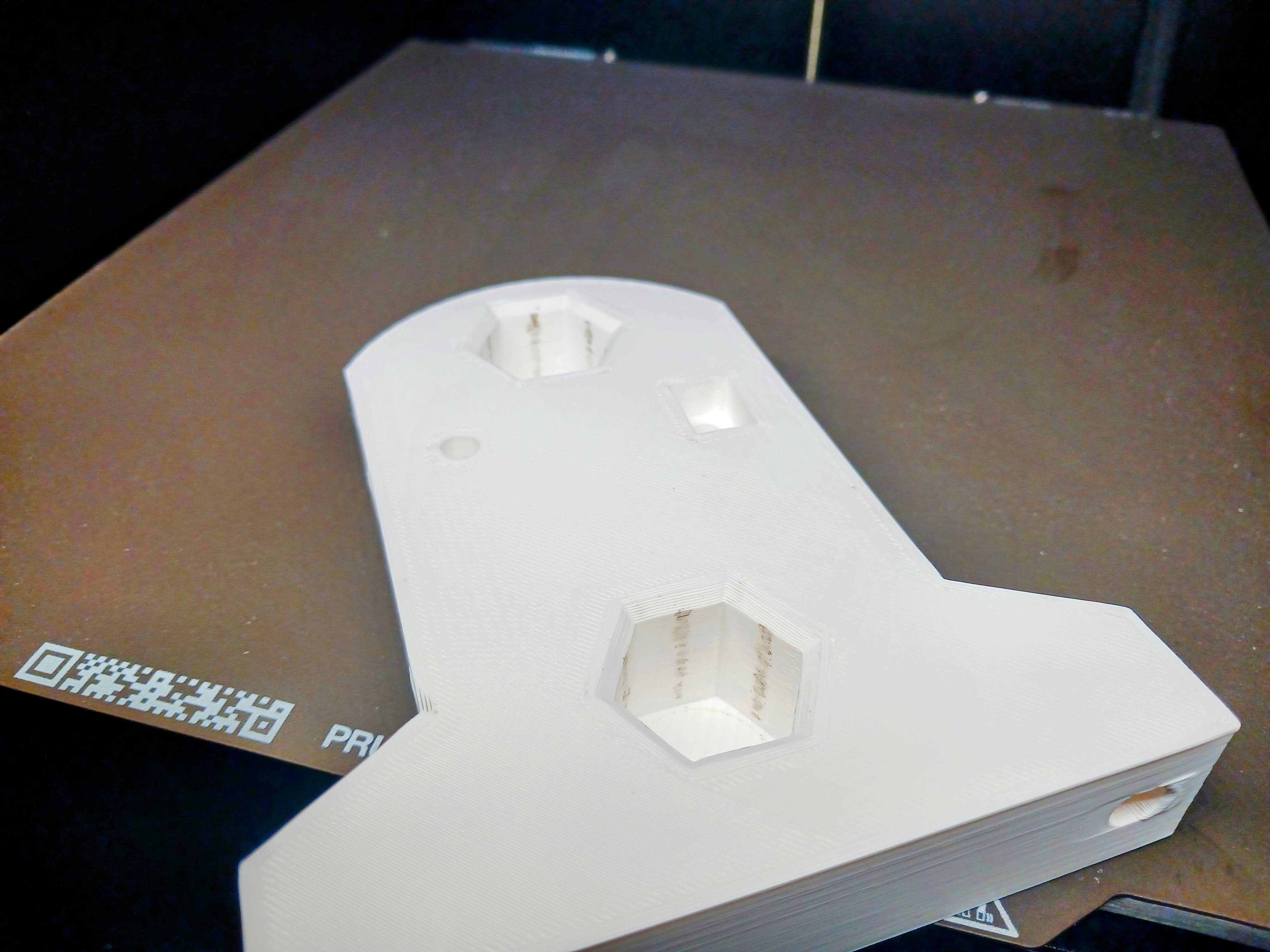
The “keyhole” was originally rectangular just like the other side to accept the ends of the rack and have a single symmetrical part that could be used on either end. That changed with V2. The round part of the recess was added so that the 1/4" nut (and washer?) can be fully recessed into the part and still be tightened to pull the end of the rack tightly into the rectangular recess on the other side using a socket. There is a 1/4" hole there but has a one-layer bridge to allow cleaner printing without support… most all holes on the printed parts will need to be finished/“reamed” with a drill bit, depending on how dialed in your printer is.
Print these parts with the rectangular recess up…
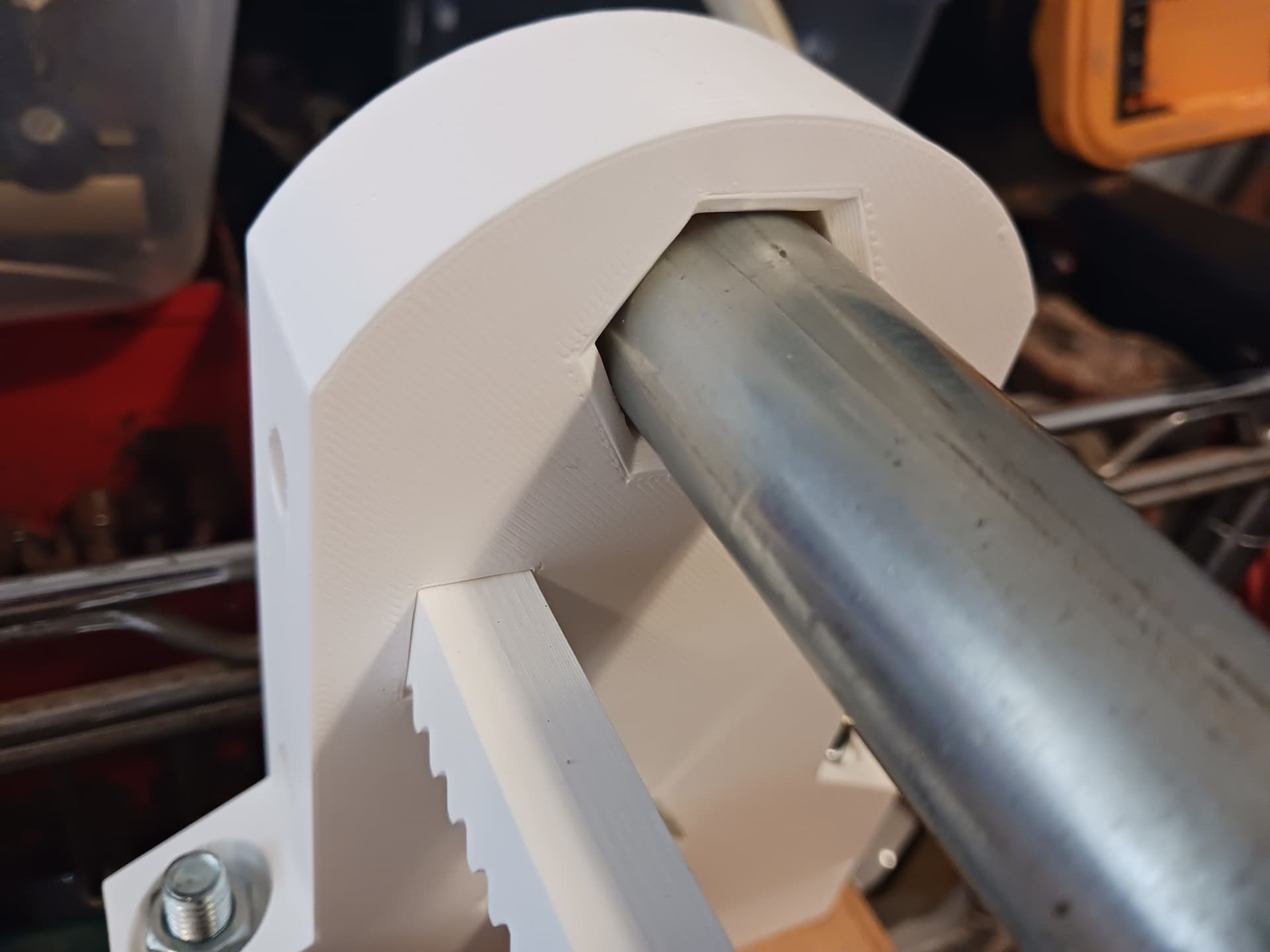
The hex recesses receive the ends of the conduit with a slip fit until it fully seats against the stop. Printed “hex holes” is a printing “trick” that allows far easier precise fitting than trying to print precise “round holes”… there’s less area of contact and a little “give” in the plastic to make allowance for different printers.
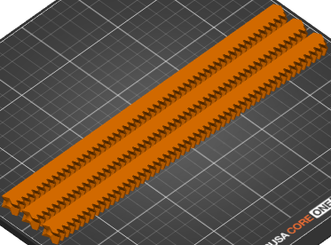
Print the rack sections on their side…
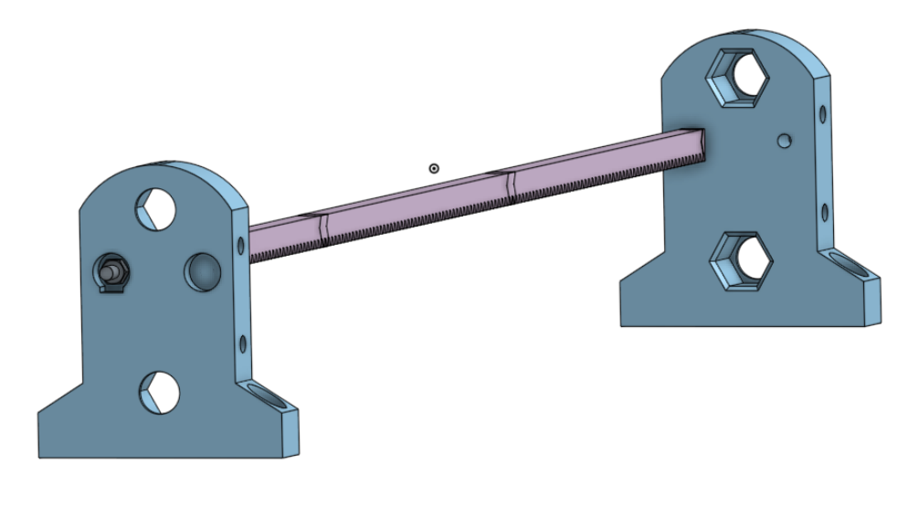
Start assembly with the end supports, rack sections and threaded rod.
Draw the rack sections and end supports firmly together, setting the overall length of the axis. Carefully measure through the hex holes from end stop to end stop with a tape measure… or maybe better, a dowel “story stick”. Cut your 3/4" EMT rails as precisely as you can to that length.
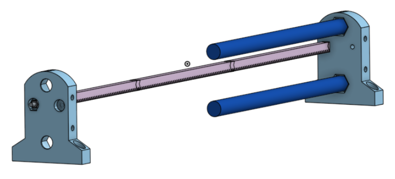
Now you are ready to start printing and assembling the carriage.
Hope that helps.
It does, thankyou.