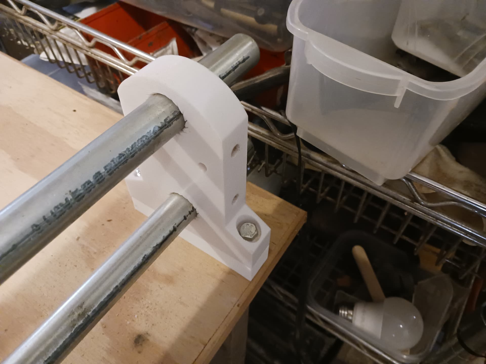
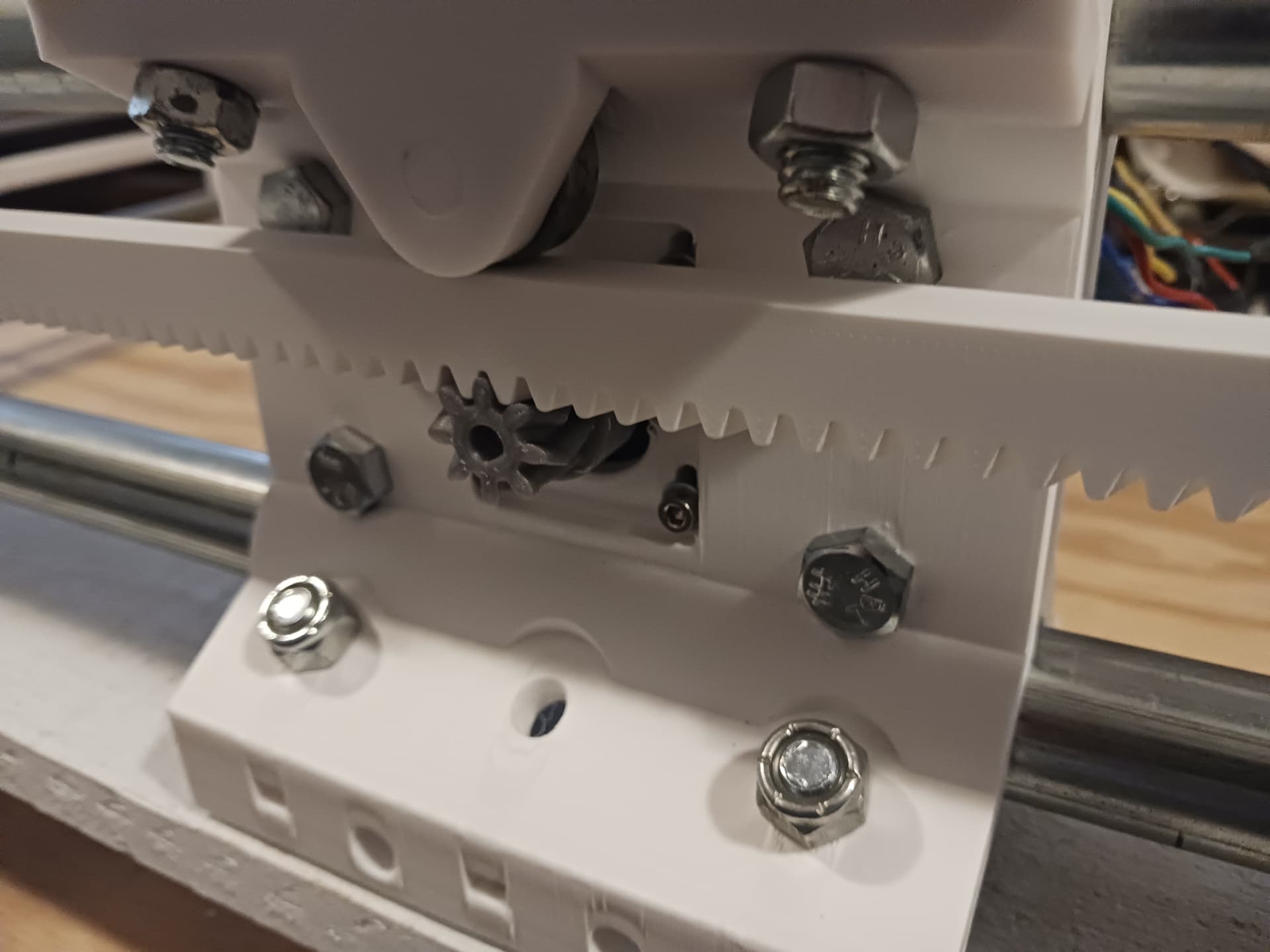
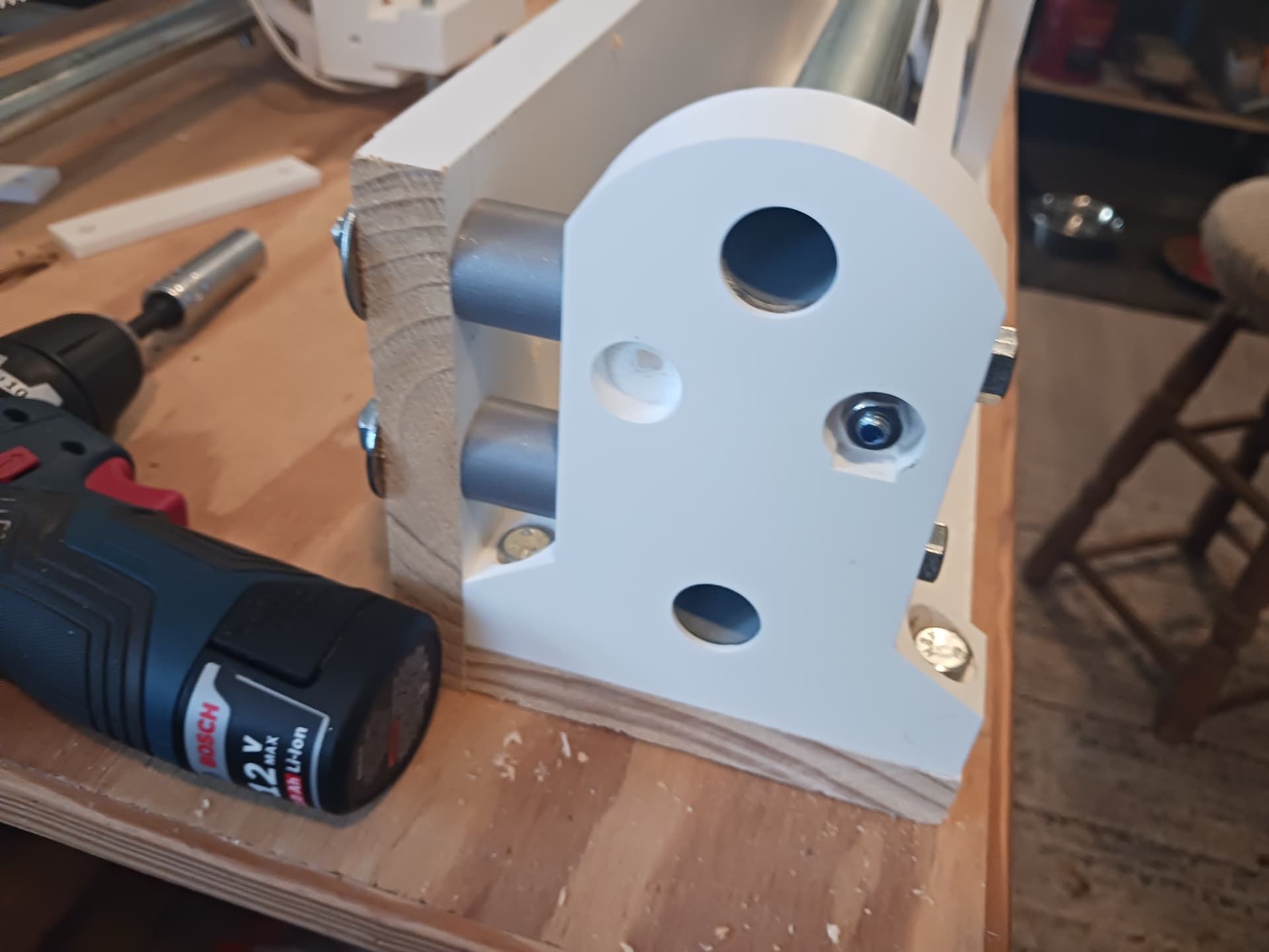
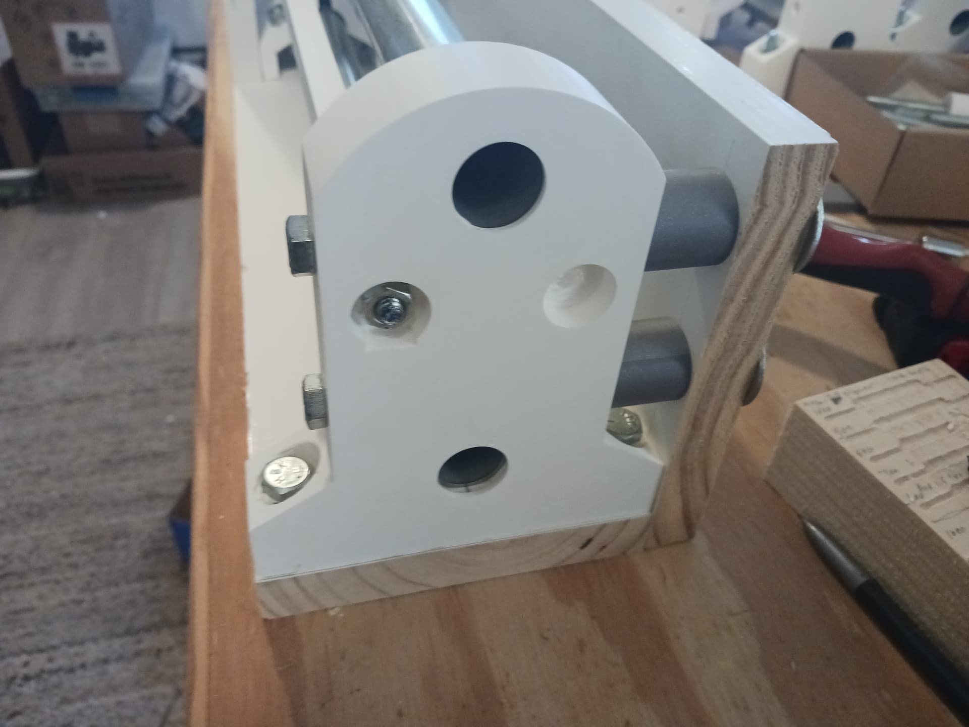
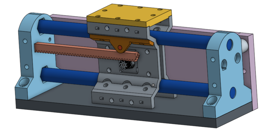
after printing some test pieces, the bolt and printed bearing setup is the way to go.
There’s far less mucking around with fiddly layer settings, print orientation, and part clearances. It’s much easier to get a consistent result with the bolt and printed bearing.
All garden-variety stuff from the hardware store and online… and I’m still working from my junk box, except for filament. Stepper motors, skate bearings, and two or three rolls of PLA/PLA+ filament… no expensive specialty stuff.
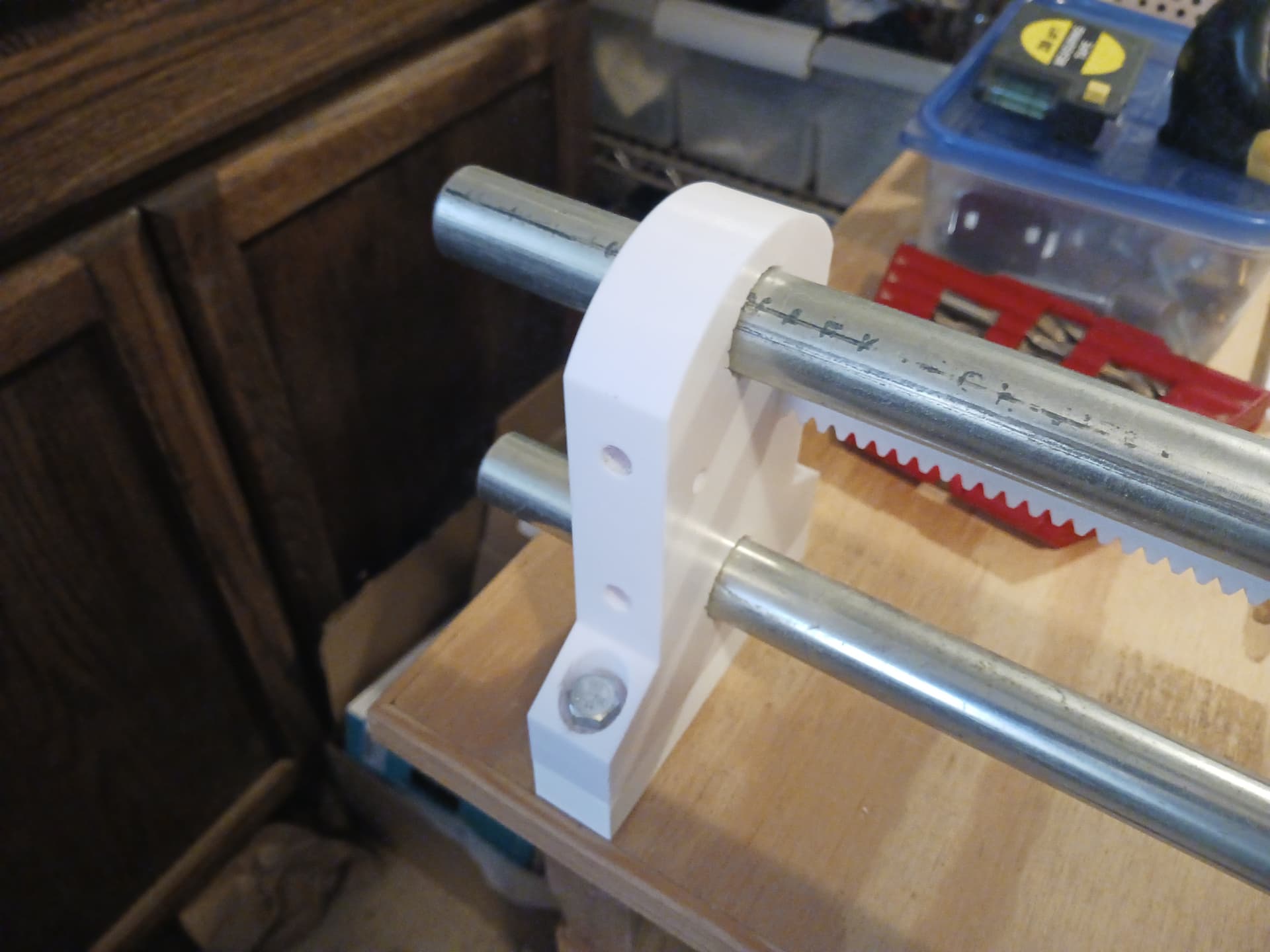
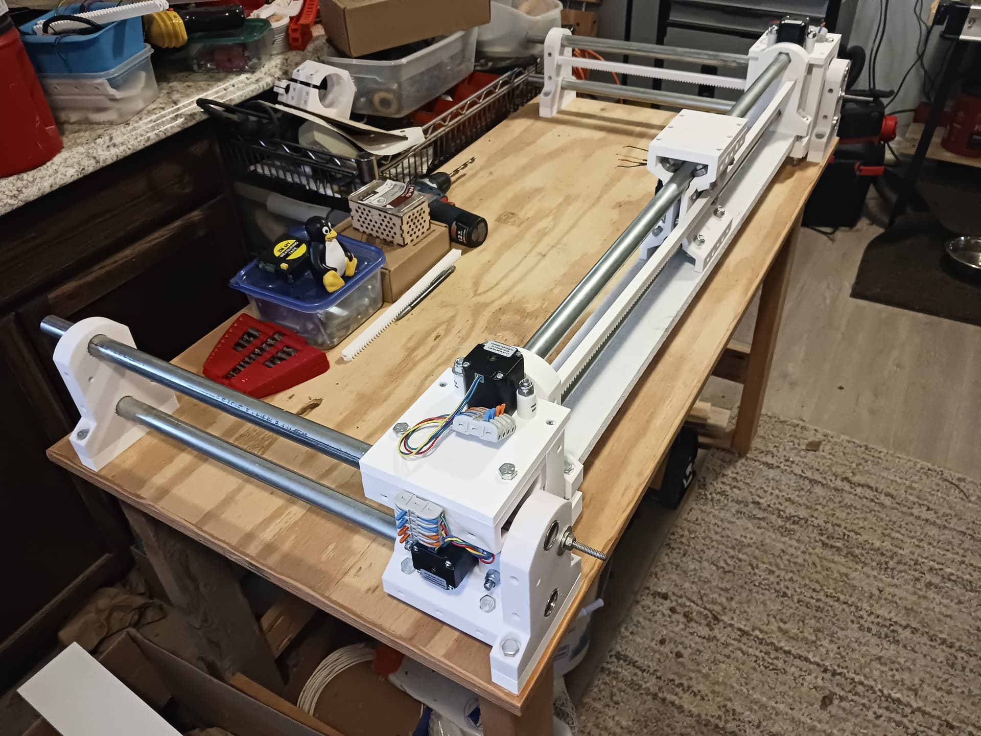
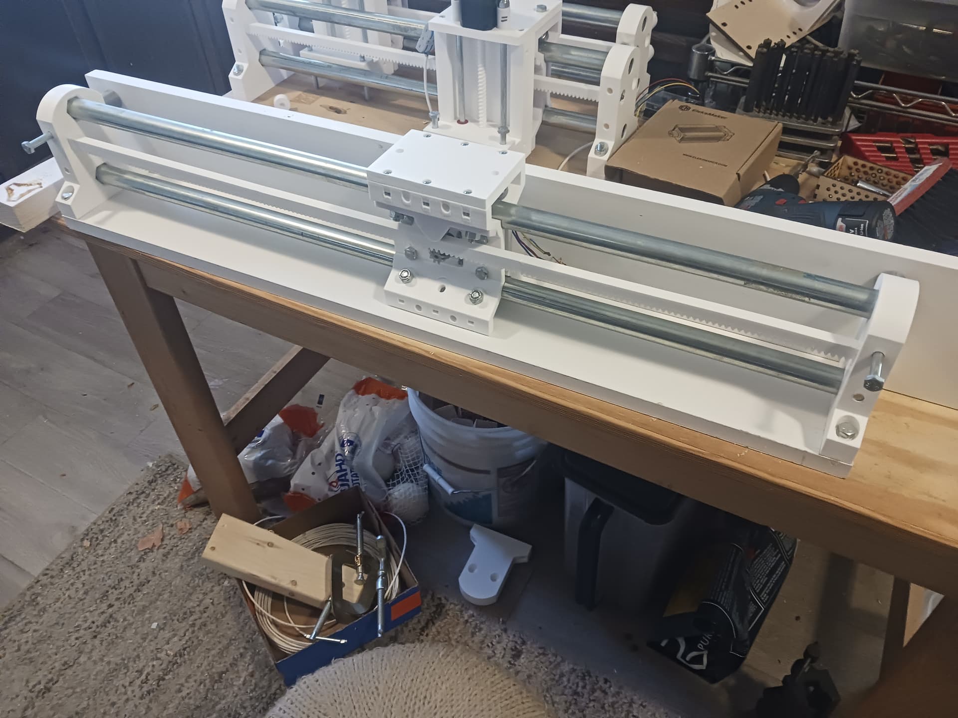
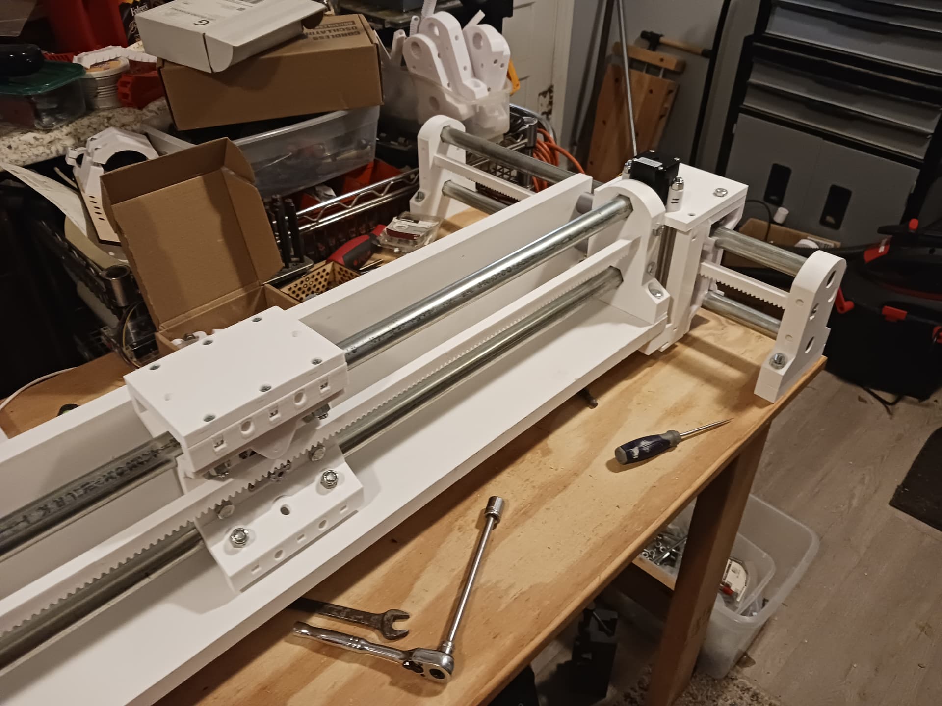
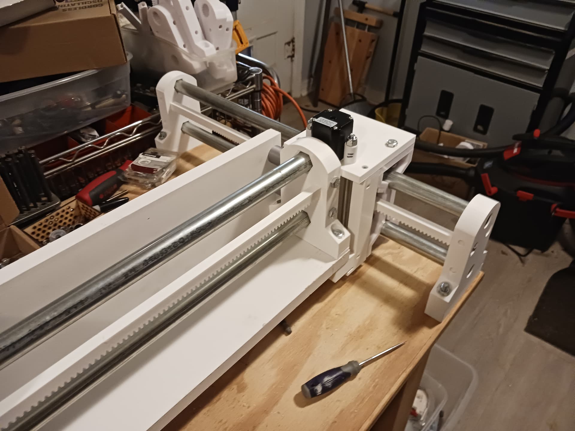
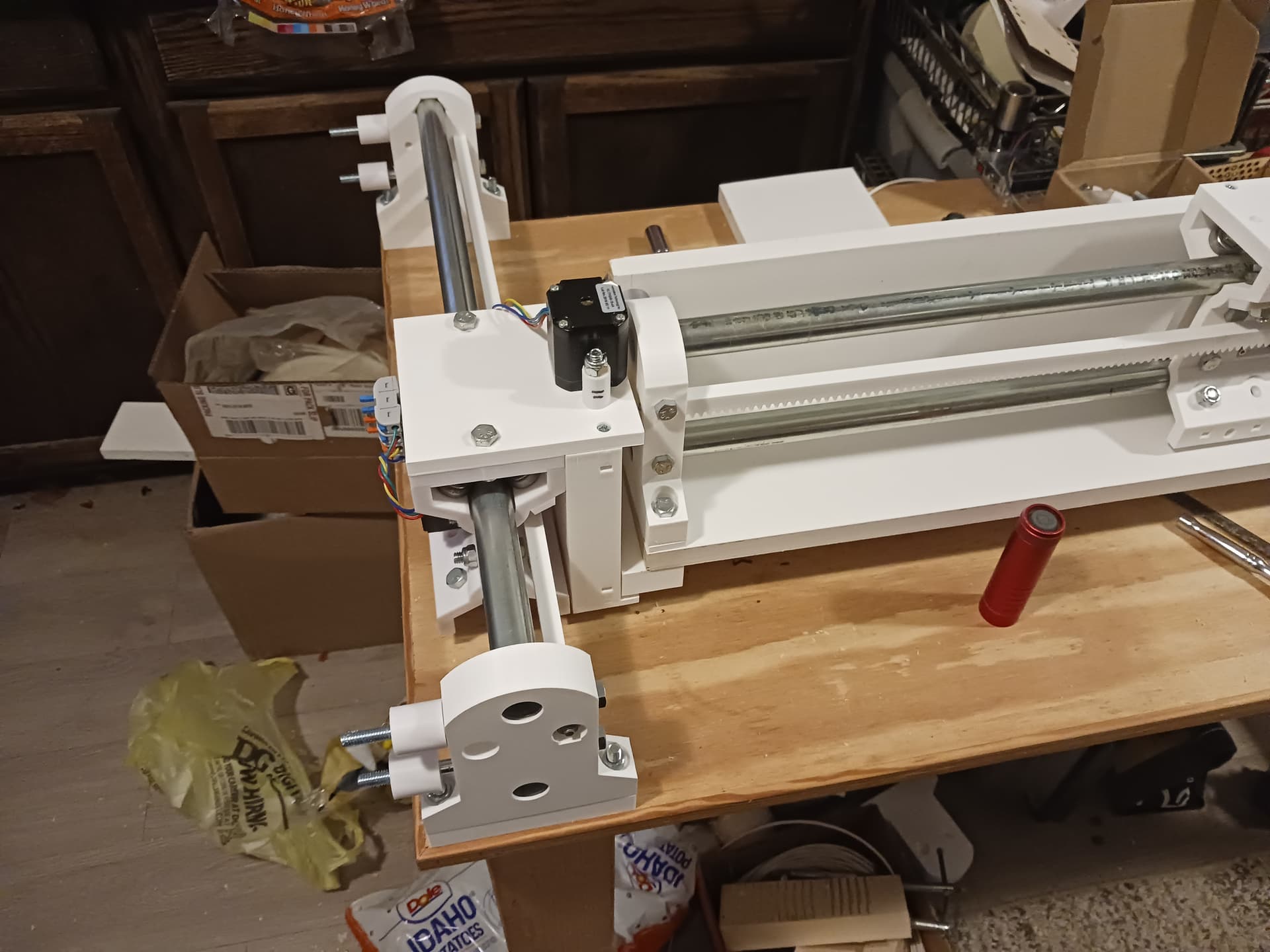
I’ll need to wire it up, of course, and see where all the interference and slop is… spacers, spacers, SPACERS! The Y-axis “wheels” are from the original MPR&P and slight part modifications – primarily the end supports – are needed to bring those up to date… but the gantry beam is now identical to the other linear stages; i.e. it’s a simpler design with fewer unique parts.
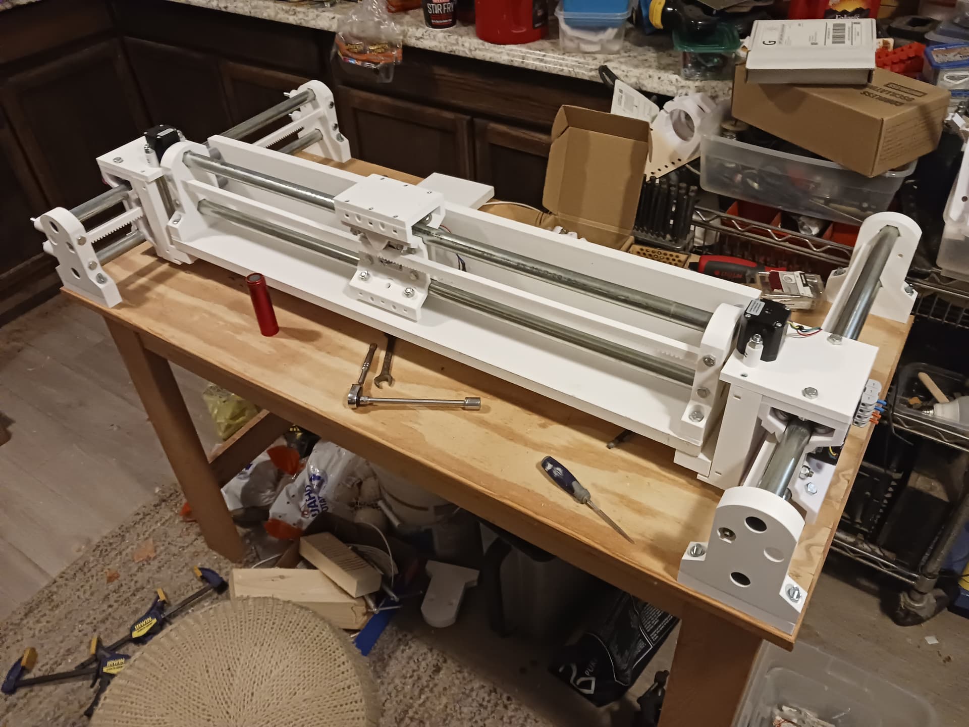
I think that with stiffener panels/boards (that’s a standard 1" x 4" board under the gantry beam… another could go across the back at 90 degrees to the lower one) in place it would be feasible to just buy 5’ joints of conduit and 6’ lengths of 1/4" threaded rod (always used in tension) from the big-box store (I know Lowes carries those…) and print enough rack sections to use the conduit as is, with no cutting… and wind up with close to a 4’ x 4’ cut area.
SIL used some very nice pre-finished/primed finger-jointed planks from Lowes during my grand-daughter’s apartment remodel project… and I found a 8-foot 1"x 6" in my scrap pile. Though I had intended to use 5mm ply panels to stiffen the linear stages, I started looking if I might use the “1-by” pre-finished lumber instead… it’s very flat and straight… and it’s already white! It’s already growing on me…
I’ll get another plank of the pre-finished stuff to put stiffeners on the Y-stages as well and start wiring it up. Been looking at the LowRider4 docs and that looks like what I should do here as well; i.e. mount everything on the back of the gantry. Obviously, it’s starting to look a little less printed now with all the “heavy lumber” attached… but since it’s already shown it can lift weights, maybe it’ll be in good enough shape to move itself around.
I hope everyone is having a very enjoyable holiday season… and got everything you wanted/needed in your Christmas stocking.
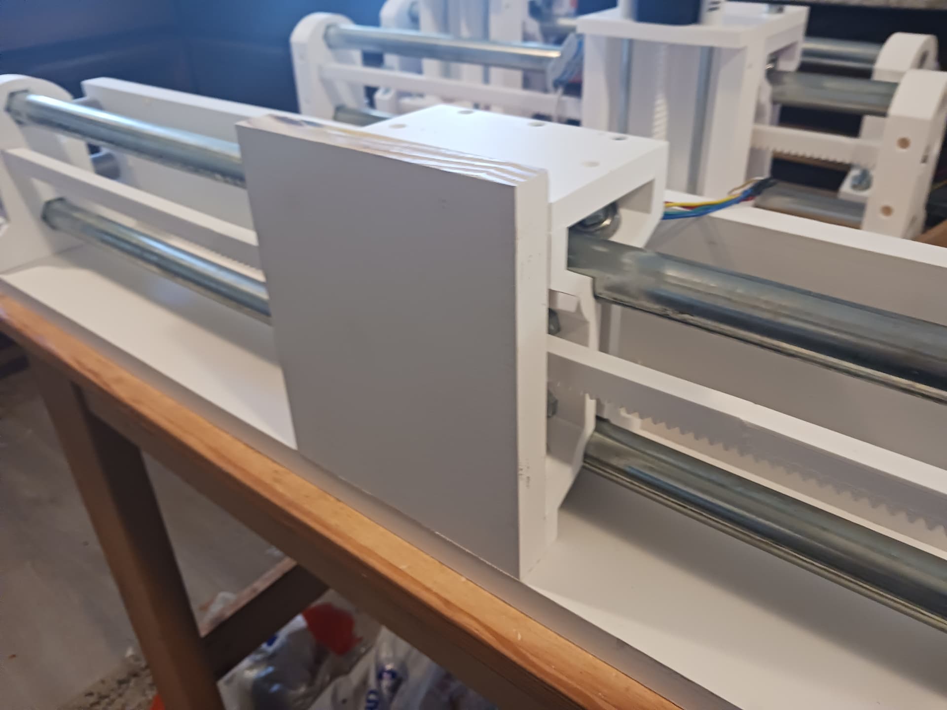
Don’t go too long with the unsupported EMT rails, they twist and flex very easily. The LR1-2 had this issue that is why the 3 and 4 have a “beam”, boxed in rails, to minimize single rail flex.
The bottom rail closes to the cutter will take most of the force, the top one basically just stops the core from twisting.
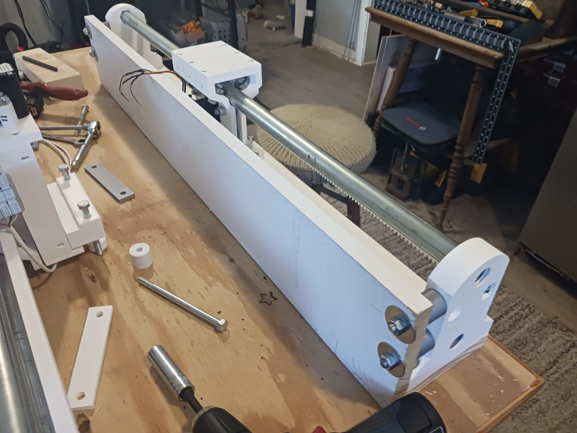
I certainly don’t plan on going any larger on my own machine… and I guess I was really just thinking that the threaded rod and rack can be as long as you want. I made this machine to fit the top of the bench it is sitting on… and the gantry’s threaded rod is an uncut 36". I was being lazy…
As far as supporting these smaller 3/4" EMT rails… attach the bottom and back board stiffeners to form an “angle beam” and put training wheels (bearings) on each corner of the lower “ears” of the carriage that track on the bottom board?
This is a legit machine. I also hate comments that talk about 3D printed CNCs as “toys”.
However… I do wonder if this could be smooth enough and cheap enough to actually use it with kids. You would want to reduce the stepper motor current to almost nothing and add in a playstation controller. Replace the tool with a washable marker and you would have a fun, educational robot that could do weird fun etchasketch style drawings. Or put on a servo and have a fun way to organize the markers or pom poms or roll dice or something. That would be pretty great.
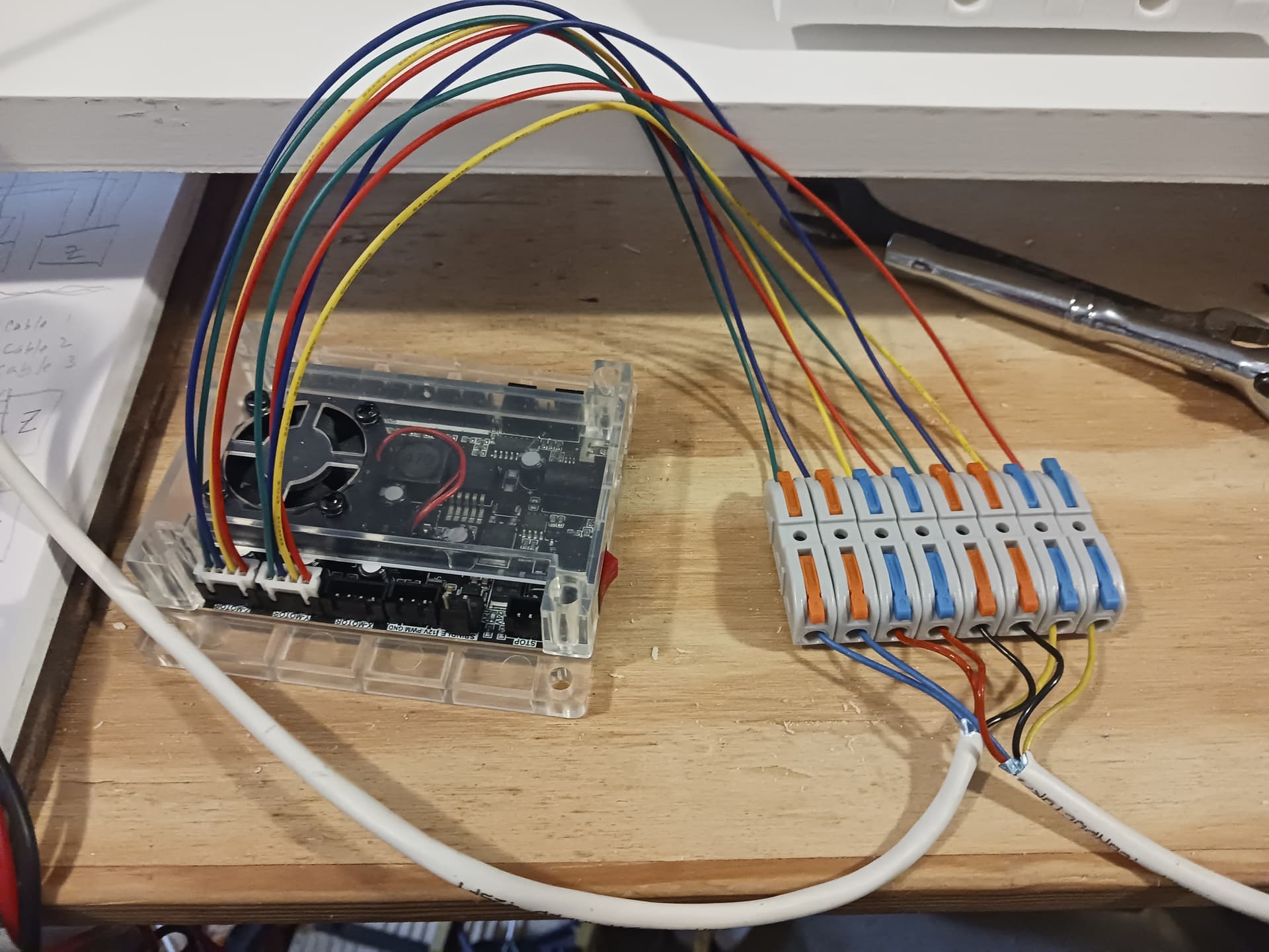
I’ll start wiring in the morning. The controller I’m gonna use is an inexpensive GRBL controller (most often found on 3018 desktop CNC machines) with three integrated A4988/DRV8825(?) drivers that I’ve used on several projects before. I did have to up the reference voltage to just over 0.7 volts and the steppers were connected in series… and that’s was enough to do the 16 lb lifting exercise in my last video.
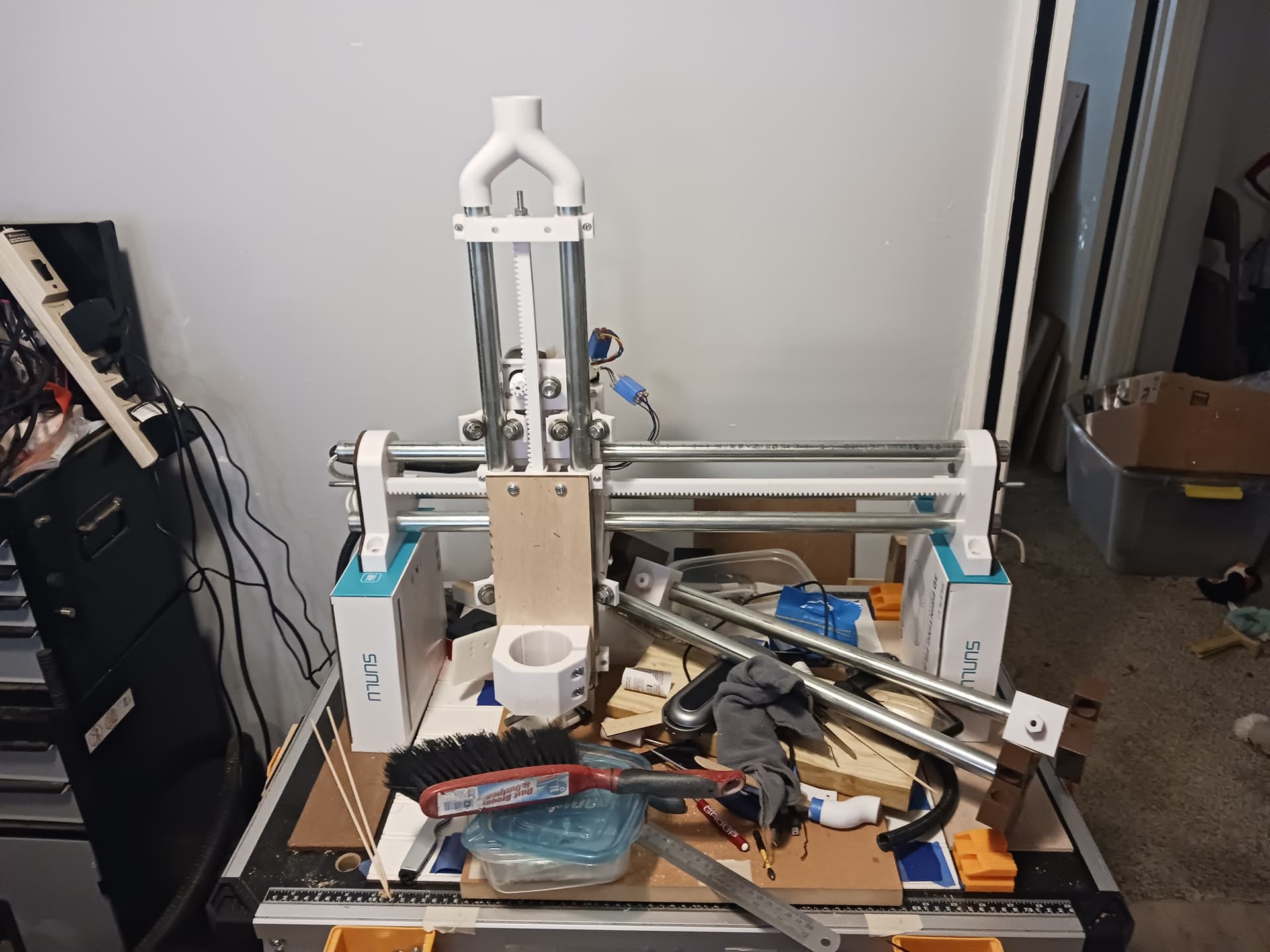
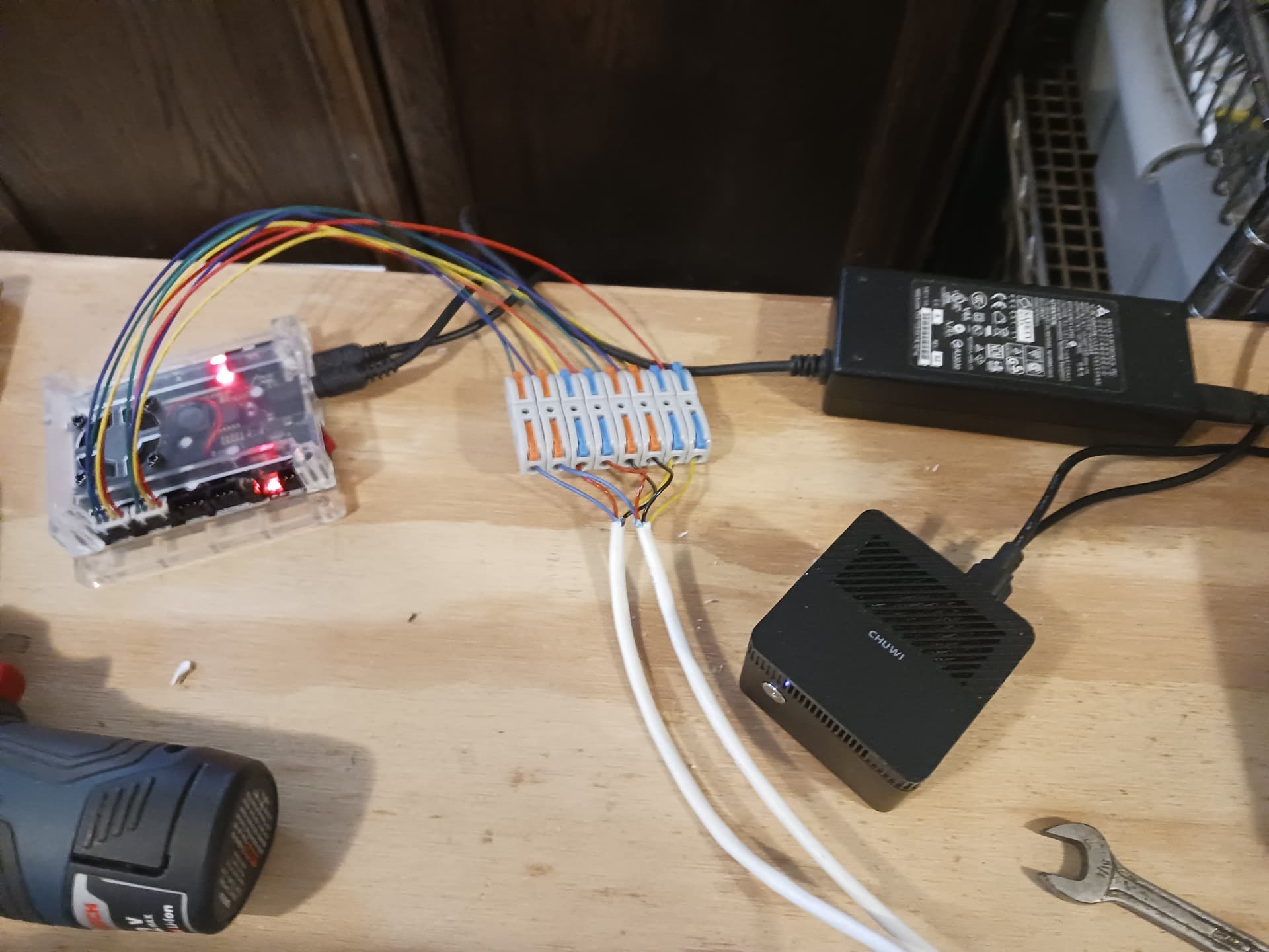
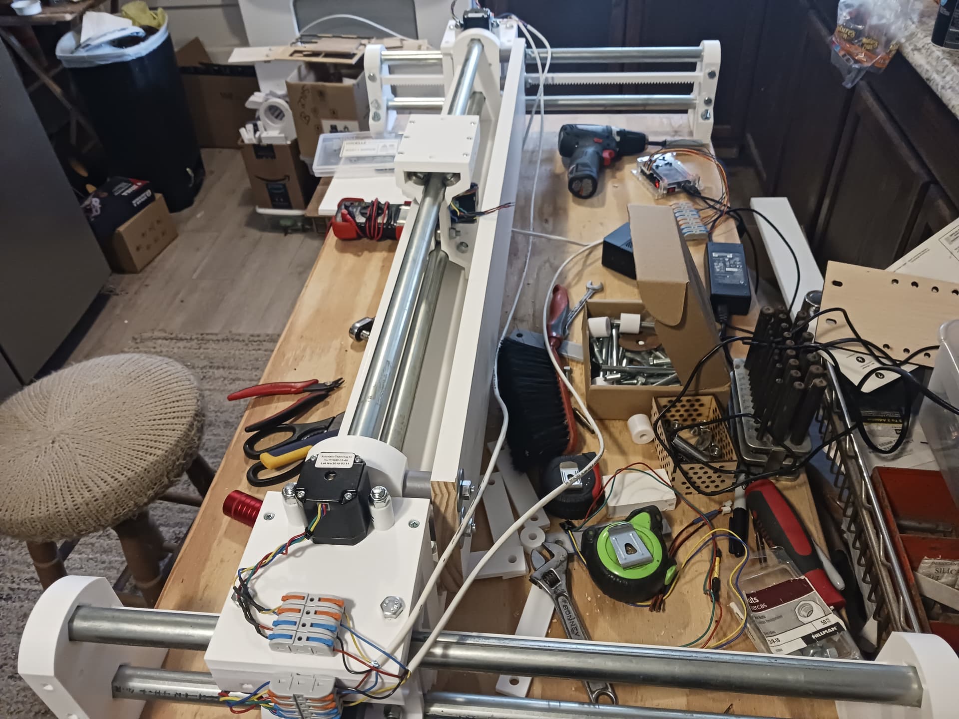
Got the series-connected Y and Z axis wired up and running initial tests on MPR&P-V2. Crappy video shows each axis traversing a 125mm range at 1000 mm/min. I’m using a headless Chuwi LarkBox Pro miniPC running LinuxMint-DebianEdition (LMDE6) and UGS Platform as the gcode sender. My cellphone is serving as a pendant for machine control. An inexpensive GRBL controller is connected to the miniPC through USB.
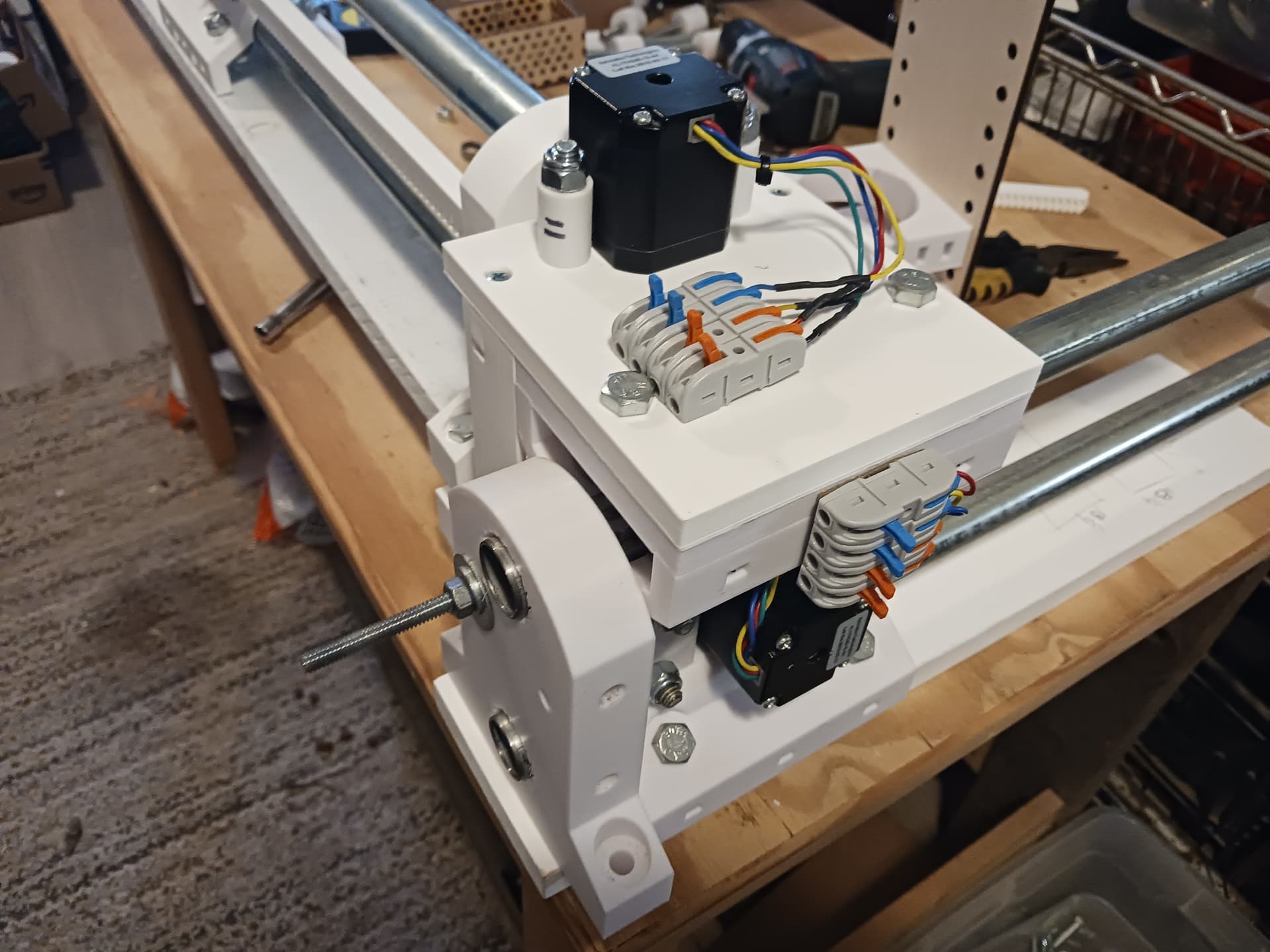
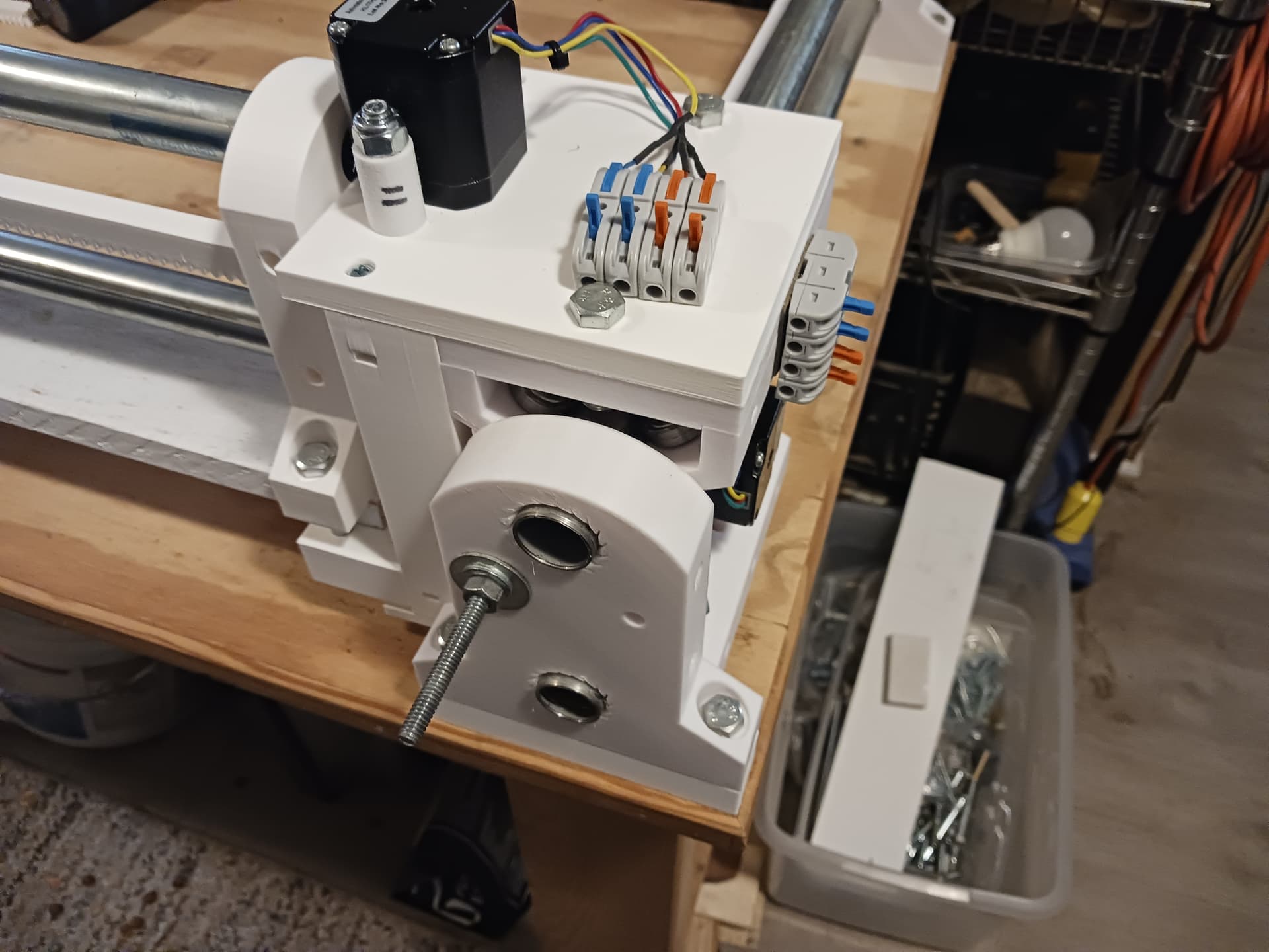
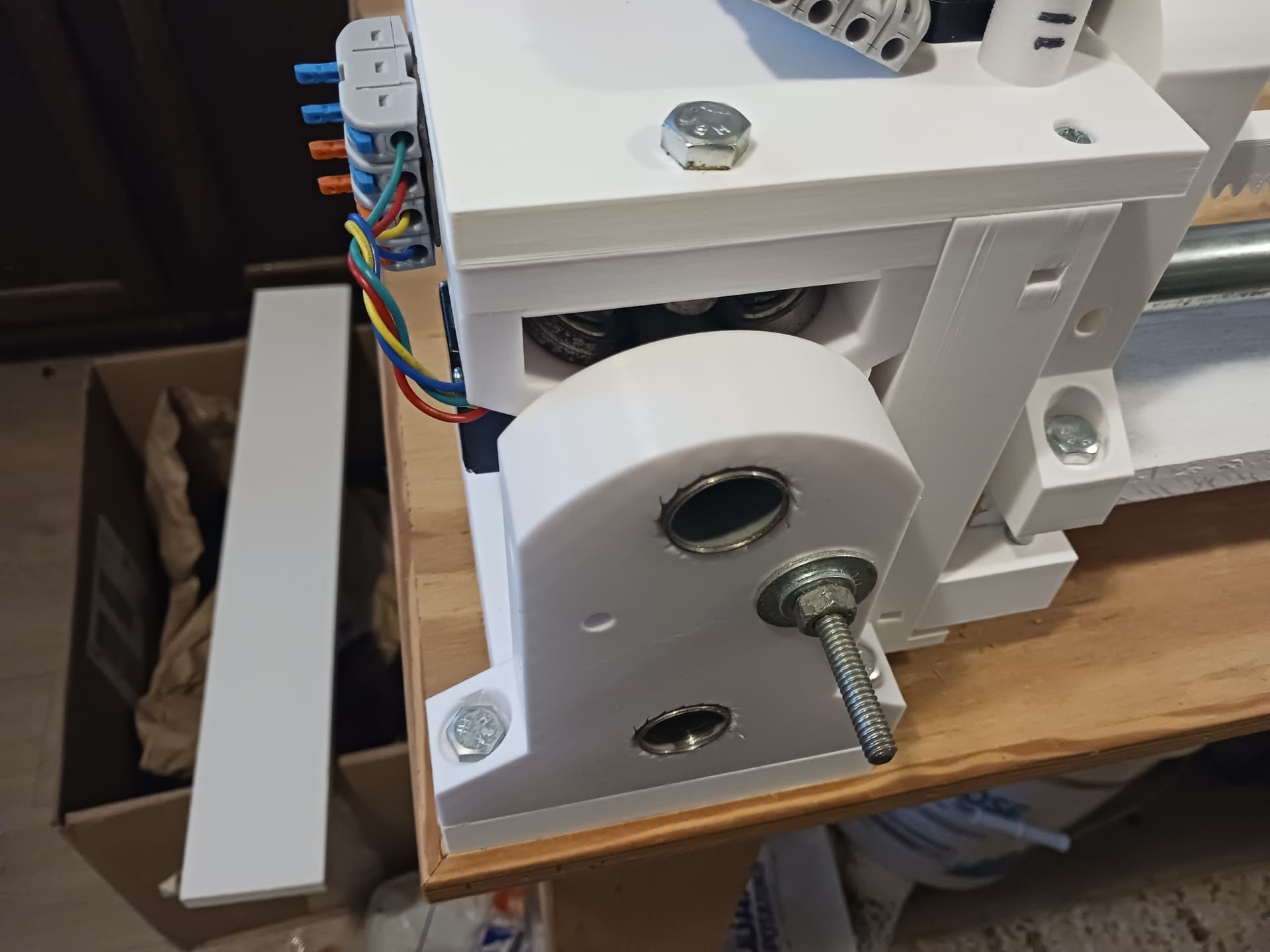
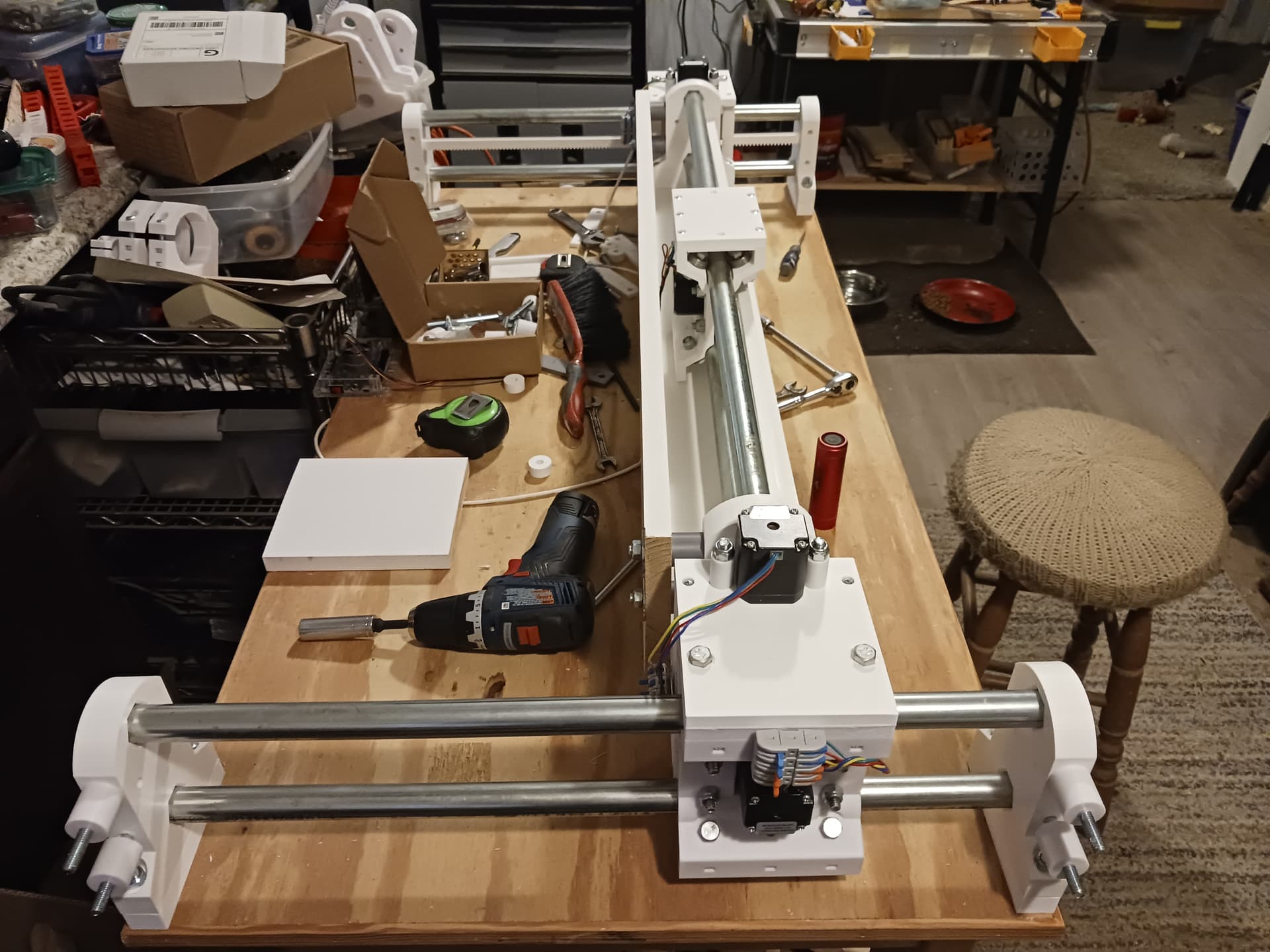
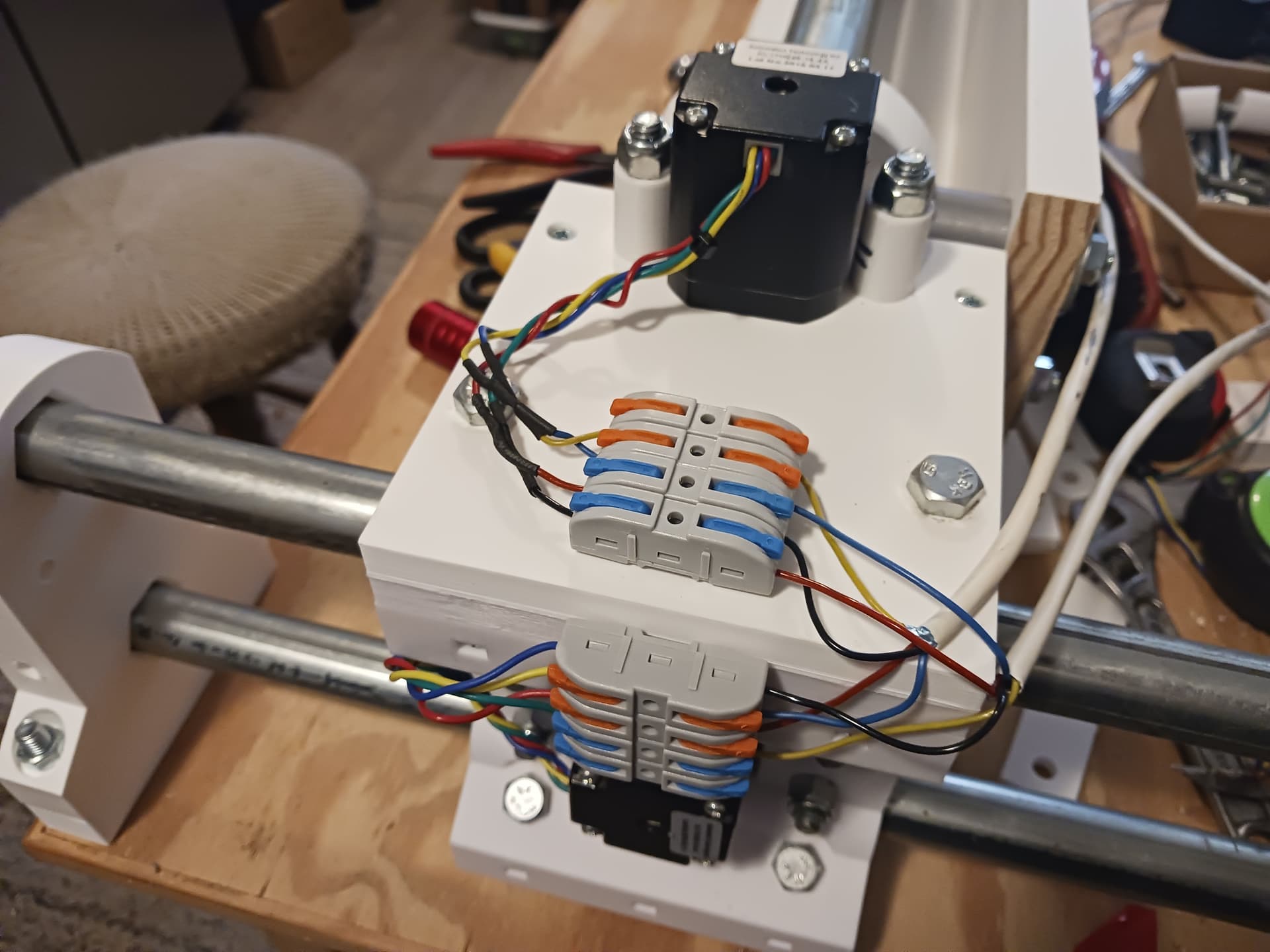
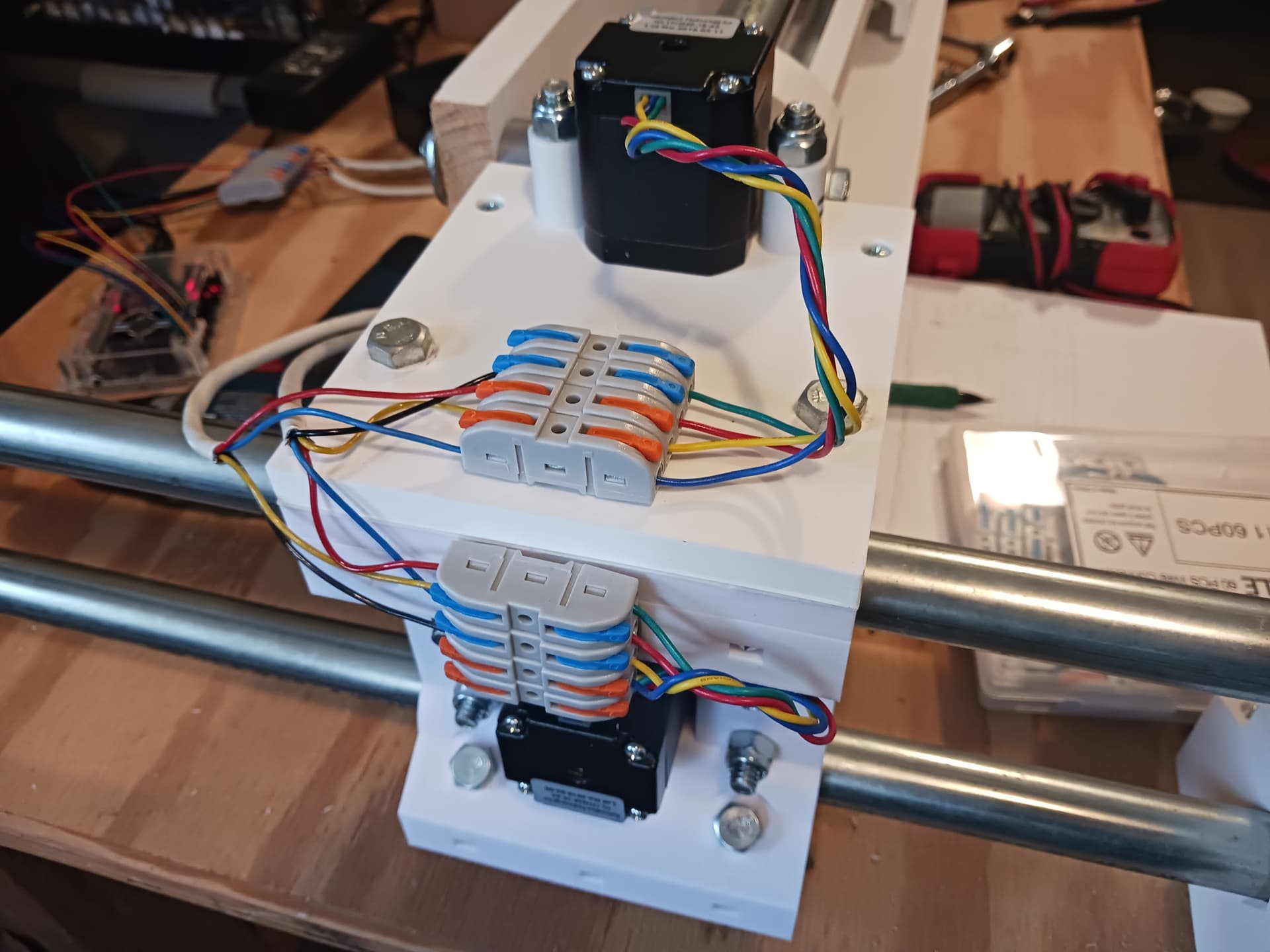
Miscellaneous photos of wiring so far… love those lever wire connectors!!!
Looking pretty good so far. The X-axis is next of course and should be straight-forward. Need to work on the wire routing and come up with a tray of some sort to mount the miniPC and GRBL controller on the back of the gantry… ala LR4.
The flat parts, would there be any benefit in those being metal?
The way the steppers are mounted means there’s plenty of room to swap them for closed loop versions. Hmm…
You could probably walk around in the big-box store and find lots of stuff that would work and look nice. Sadly, I’ve reached a point where I get anxious and nauseated when I go into a store and try to just “wander around, looking at stuff”. If I know what I want beforehand, go straight to it, grab it, and checkout as quickly as I can… I’m okay. Normal folks won’t have that problem.
Initially I was thinking thin plywood… maybe some 5mm underlayment? I can laser cut that on my Roly 30W laser machine but it can have considerable warp?
Some manufactured solid wood finger-jointed panels and boards are really nice… flat and straight. Sealed against humidity and moisture, surely they can work.
Tempered hardboard? Might be flatter than plywood? Lots of wall paneling stuff would work, I’m sure.
Sheet steel? I’ve bought some of that for worksurfaces under my laser machines.
How 'bout metal drywall studs? I’ll bet there’s all kinds of neat metal stuff back in that department.
After playing around with the pre-finished finger-jointed boards, I’m beginning to wonder if it would be best to fasten the back and bottom panels/boards together to form a “wooden angle beam”? Being as the gantry is being lifted by its ends, it seems to me that the gantry should be as stiff as possible?
I suspect any number of things would work. Use what you’ve got on hand or can easily get at the local store. That’s the fun of it for me.
Got the X-axis working and cobbled together a crude pen-plotter… with the pen and mount doing quite a bit of flexing. The Spongebob gcode file was an existing file for another machine so the Z moves are really clunky yet. But it seems to be going through the motions… so that is encouraging. Didn’t have a crown gcode file handy…