With my prototype MPR&P now languishing because of a lack of motivation and hatred of the noise and debris… a new Prusa Core One L printer has rekindled an idea bandied about during that fun first build.
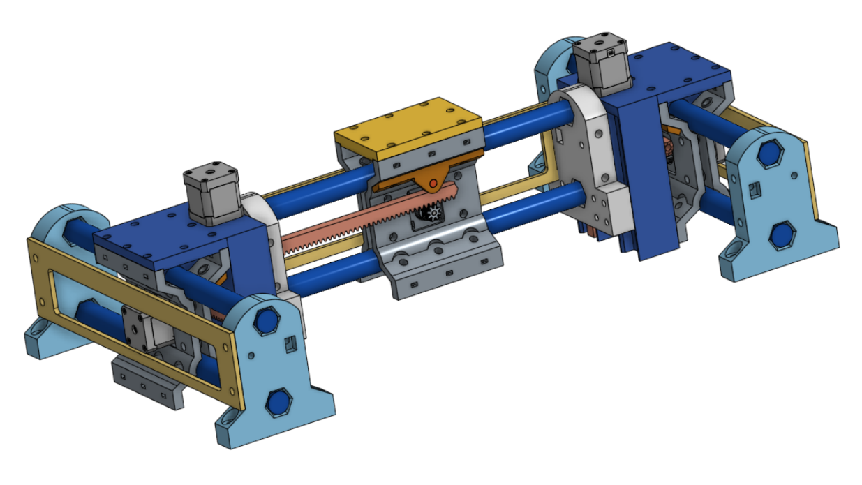
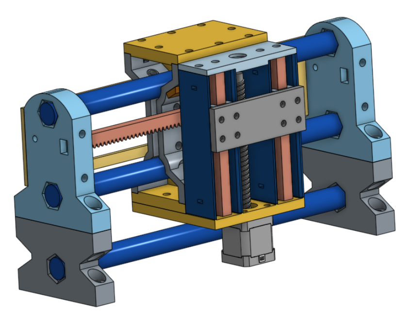
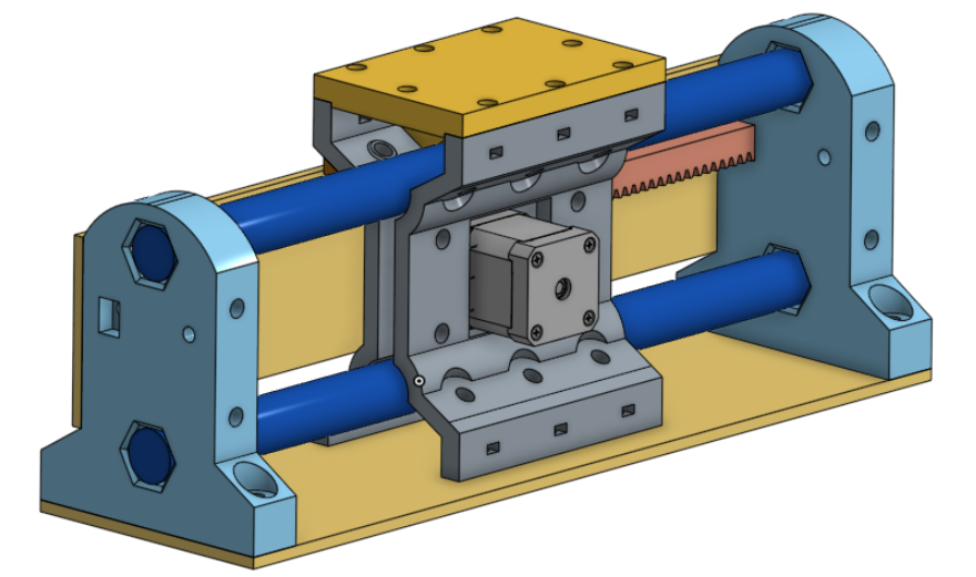
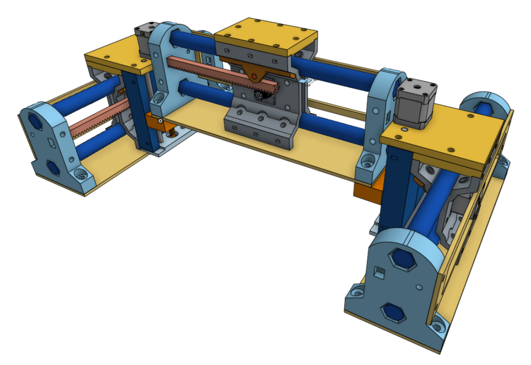
What if we married a LR4-inspired beam and lift assembly with MPR&P’s “standard” linear stages?
Much lower COG and rigidity at the expense of bulkier gantry ends?
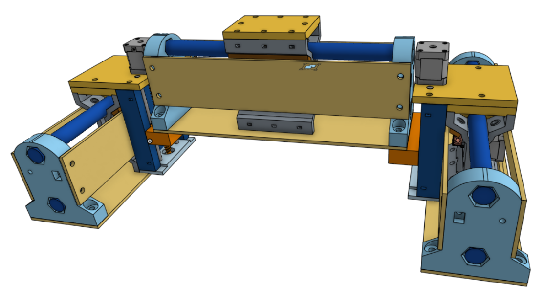
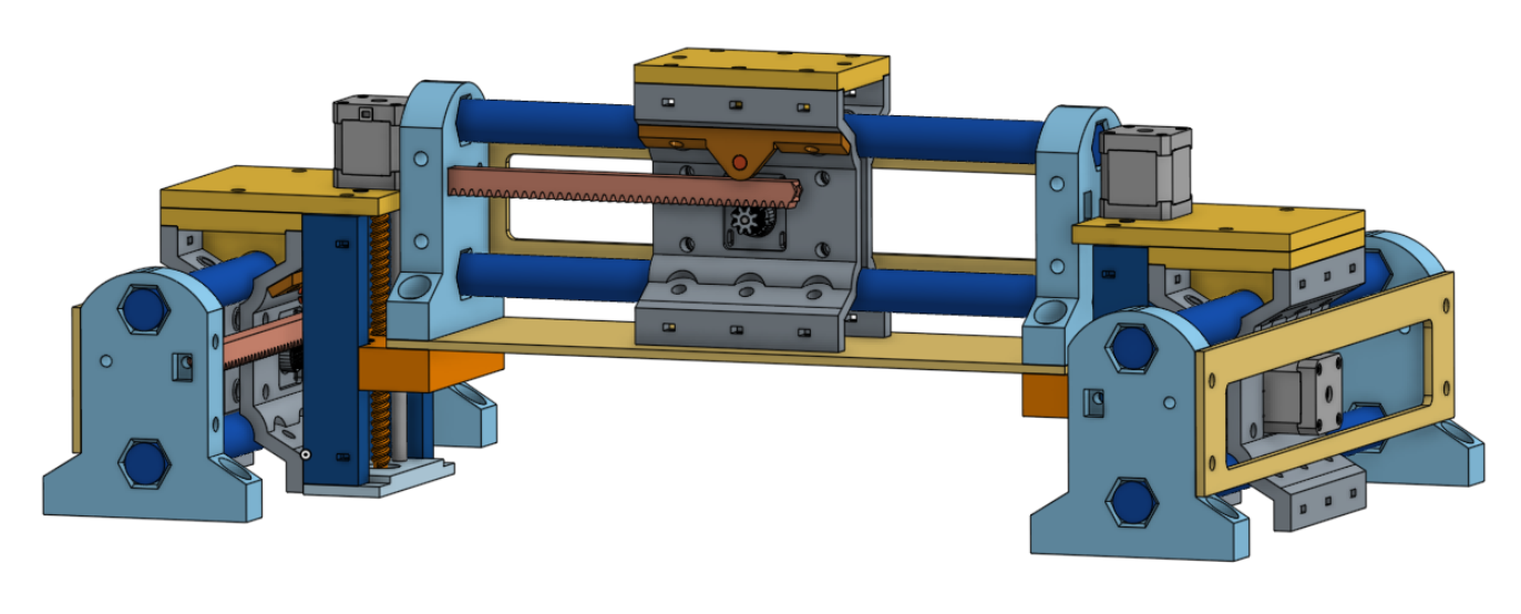
This obviously needs a lot of adjustment and refinement of parts design and relative placement and spacings but it could use almost stock linear MPR&P linear stages and the addition of two new Z-lift assemblies. Sadly, it does do away with the R&P Z-axis of version 1 but it looks to me there’s lots of ways to make the beam much more rigid… with flat ply panels along the back (as shown) and bottom connecting the gantry ends. I bought a set of LR4 linear guides from Ryan and this looks like it could be a fun project for the new printer. I’ve got LR4 leadscrews on order as well but for now I want to test with a printed leadscrew, similar to one of my motorized Z-axis mechanisms…
I’ve held off posting this because I really hate it that you guys with new Prusa printer orders are being jerked around so by FedEx… while my machine was delivered without delay or difficulty. But since some of your orders have at least now reached the US, I’m trusting it won’t take more than a day or two for your machines to be delivered. Again, I hate that your machines have taken so long during shipping… and continue to hope your machine gets here soon.
I suppose so… but my machine was ordered Friday late evening and delivered on the following Wednesday at 2PM. It spent most of its time in Europe and got to Memphis on Tuesday afternoon… and delivered next day.
No complaints from me, of course, and I can only hope for a similarly quick US delivery for everybody else.
Your printed rack and pinion is stuck in my brain. It is really a nice low-cost option. I have sketched up a few things but I keep getting sidetracked with other ideas. This really feels like the best next gen MPCNC to open it up for more schools. I love following along with your progress.
I’d love to have someone who knows what they are doing – not me! – print up a R&P test stage and put it through some rigorous testing. It’s always nice to hear flattering things said about “potential” but I have this nagging fear that it won’t be as strong or robust or long-lasting as hoped. I know I can produce a few accurate items – rulers and Jamie’s test patterns – and do some lightweight testing but I never play with these things long enough to see what they can really do… and for how long. Once I’ve satisfied my curiosity I’m usually ready to move on to something else…
I am trying to get set up to actually test the new full sheet lr4 I built with a indicator to see where the errors are coming from and at what loads. That has been on my to-do list the longest. From there we will all know where to focus our efforts.
But, just knowing these are working is 90% of the battle. Any design can be tweaked after the fact, or materials changed to compensate for any lack of strength. Heck, it could just be a CNC pen plotter for actual CNC training, it would not have to be actual cutting if it really comes down to it.
I’ll be really interested to see not only your results, but also your test setup and methodology. If nothing else, to repeat it with some MPR&P setups.
@dkj4linux - so have you printed any of these yet? I have some extra LR4 and MP3DP linear rail and would play around if you either get anything moving or have anything you want someone to try printing.
I loved the stepped sizes of pritned rack that you made, I should fire up some more of those on the smaller machines while I’m reorganizing my ragtag collection of machines to make way for the new Prusa.
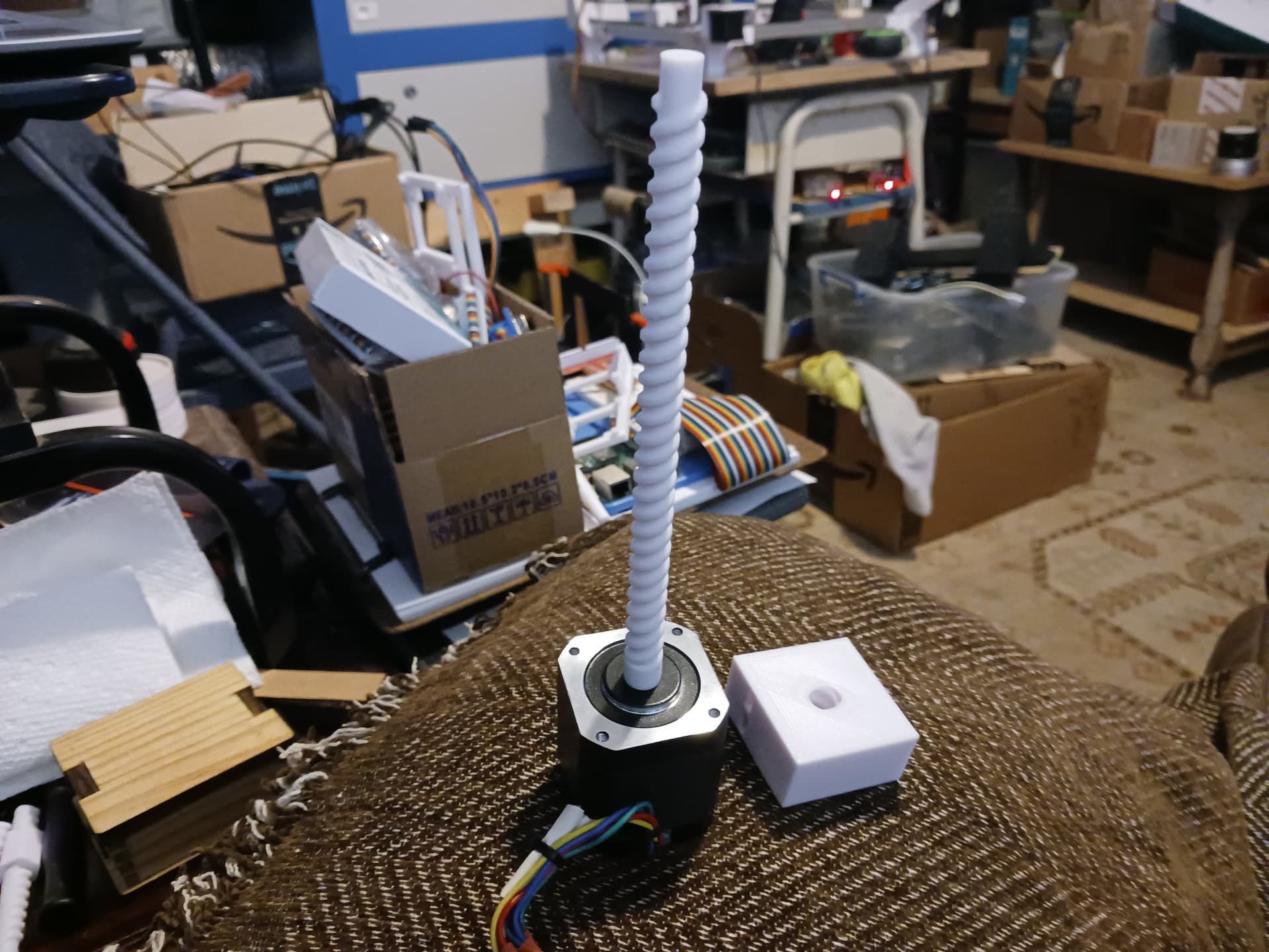
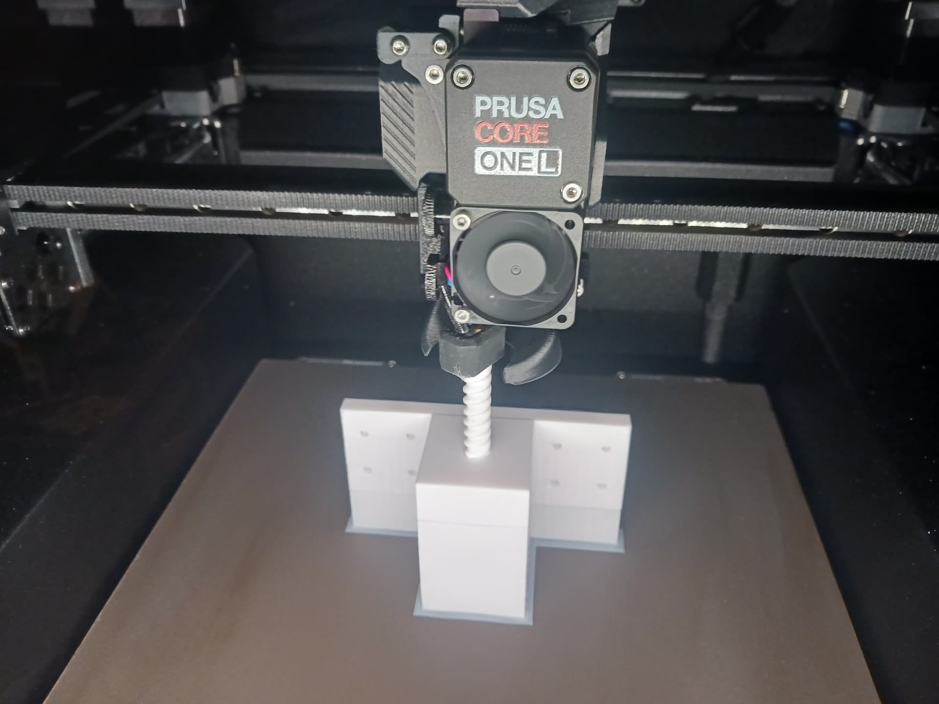
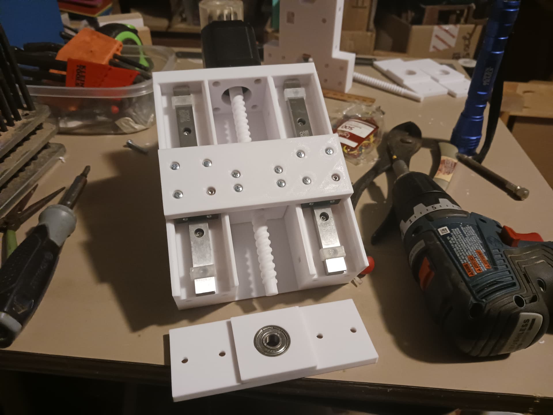
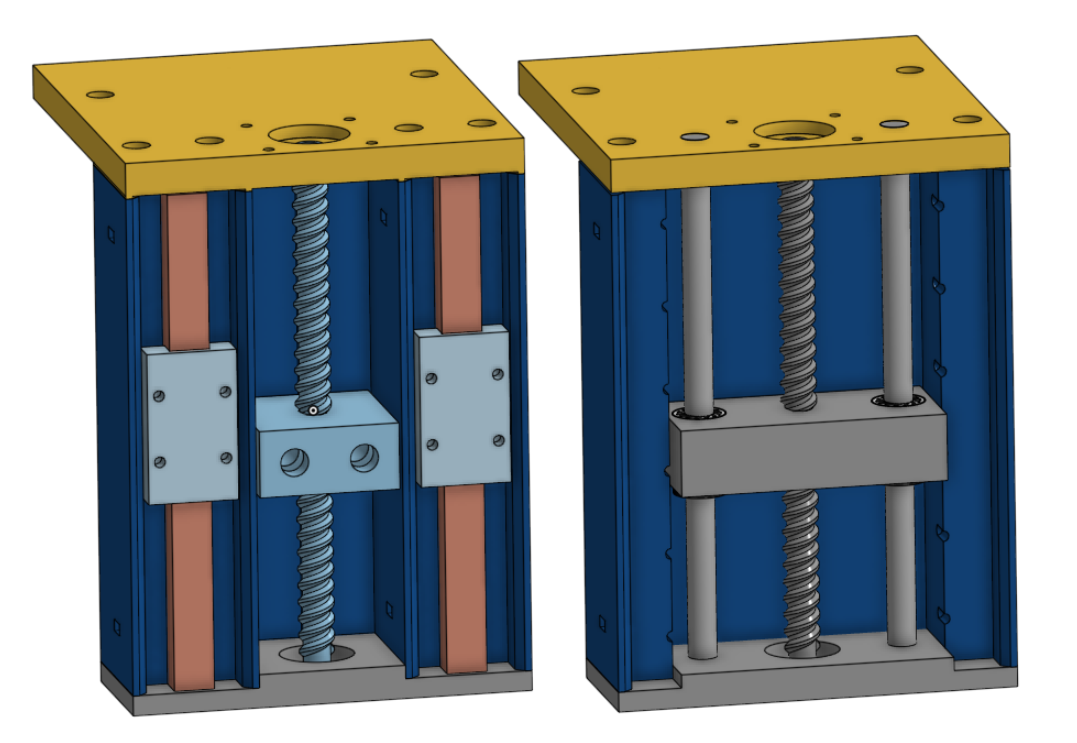
Am currently printing a slightly shorter leadscrew with integrated nut and plate… a print-in-place. They must be printed together to keep matching pitch. Don’t care about actual pitch value… I can adjust the steps/mm during calibration.
The linear slides are Ryan’s 150mm LR4 slides. Should have something moving tomorrow… er, later today. As soon as I have a semi-workable lift assembly I’ll be happy to provide .3mf files…
I think those are great to test with but if it was a long term thing the motors need to be on the bottom sot the screws are always under compression not tension.
Thanks for the input, Ryan. Wherever possible, I’ve always tried to design in symmetry… always pays off somewhere down the line with fewer unique parts and multiple orientations. Y-carriages are symmetric and should allow Z-motors on bottom. Just add support legs from original MPR&P to clear…
Something I really like about the MPR&P and the LR series is how you can do bootstrapping. You can print the MPR&P and then start using it to mill upgrades for itself.
That’s like how a basic LR4 sitting on a garage floor can cut its own strut plates, then cut its own table, and then start cutting aluminum strut plates or XZ plates, etc.
Then you can go nuts if you want and make whatever.
I also really like how collaborative something like an MPR&P is. It can be split up so teams of students can all work on making parts to build and then upgrade the machine.
3d printed rack and pinnion seems like it would be plenty strong. The old wades extruders worked great even when printed on horrible printers with bad filament. New far more accurate printers and new filaments I really do not see a reason that would not work. What is the worst case some $0.50 prints wearing out every 100 hours of cutting??
I really like this idea. I would much prefer to know I offer a very low cost boot strappable machine before even considering a “pro”.
I just happened across an older i3 style (bed slinger) 3d printer and it uses a guide rod and a lead screw for z.
In my recollection, the linear bearing tends to be the cost driver in this setup for z. Is it more economical to use a rod bearing in this case for economy or is it trading off too much rigidity or complexity?
I doubt you could be much cheaper than the rod guides and printed leadscrew shown in this video…
This particular laser engraver Z-axis shown used garden variety 5/16" x 6" bolts from the big box store surrounded by printed linear bearings. Who knows how long they might last as Z-lift stages in MPR&P-V2? The same question could be asked of any other of MPR&P’s printed parts… the printed R&P parts, in particular. But as Ryan noted above, repair and replacement of printed parts is miniscule while their function might be good enough for long enough to be quite handy and useful.
The MPR&P-V2 will utilize the LR4 linear slides I bought from Ryan… because I have them and it’s LR4’s beam and lift setup I’m looking to duplicate. I might use the LR4 leadscrews as well… and I have them on order. But I also wanted to play with the printed leadscrews as well… they are fun to make up in Onshape and printed-in-place, with the only real cost being time and filament.
So, a really cheap mostly-printed machine with surprising accuracy can made that will last long enough to at least see it’s potential… if not longevity. I’ve made several machines like this… the R&P MPCNC, a MPCoreXY laser engraver with printed BB-bearing linear slides, the original MPR&P, and bunches of manual and motorized Z-axis for laser engravers. The original MPR&P was a substantial project and cost almost nothing, except time and filament… working from my junkbox and printing almost all the parts.
To answer your question… the rod and leadscrew is definitely more economical than the linear slide and leadscrew setup. And, at this early stage, I don’t think anybody really knows the trade-off of rigidity and complexity. Until a few of these things are built and actually put to use, I doubt we’ll ever know.
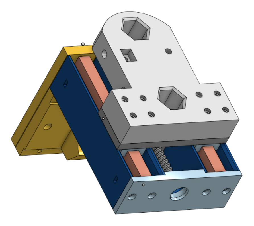
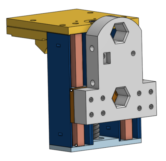
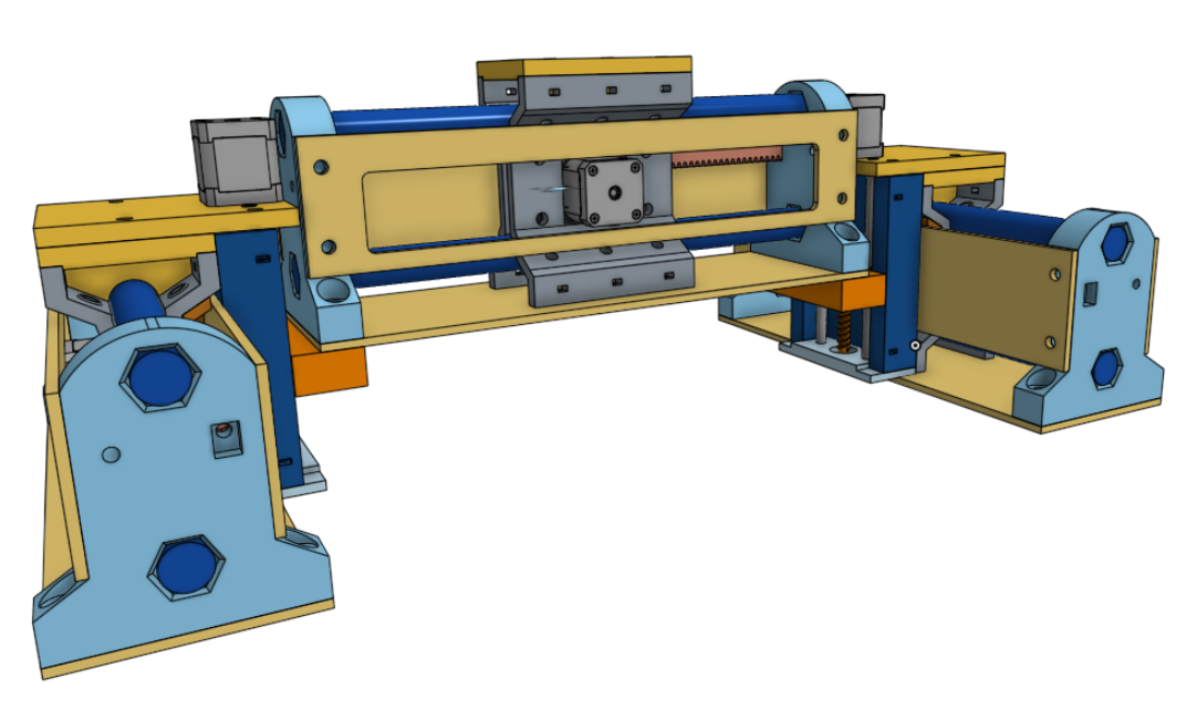
Now that I’ve thought about it some more and there’s been several musings/comments on what a most economical MPR&P might look like… I’ve rethunk my comments about what the MPR&P-V2 Z-lift assembly could look like with rod guides instead of linear rail…
Even if you purchased common 8mm or 10mm polished rods and matching LMxUU linear bearings I suspect it would still be considerably less expensive than the MGN12 linear rail. I think I’ll continue with that idea in mind.
It appears that my Amazon PLA filament order is out for delivery… a day earlier than originally planned. I should be able to cobble something together in the next day or two to demo.
Been printing lots of test parts after switching back to PLA from PETG experiments. I love the new CoreOneL printer though I’m not too crazy for PrusaConnect and its internet connection back home. The machine seems a bit too smart in some ways… but I do like being able to control it from my recliner.
The guide-rod Z-lift is coming along slowly… while also needing to work on some Christmas gift ideas. I’ve still got adjustments to make for the Z-lift assembly and am printing test parts right now… still hope to demo today.
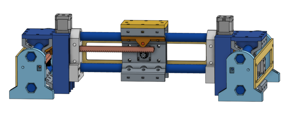
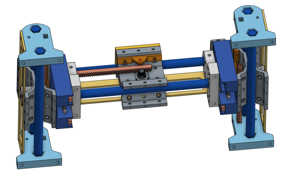
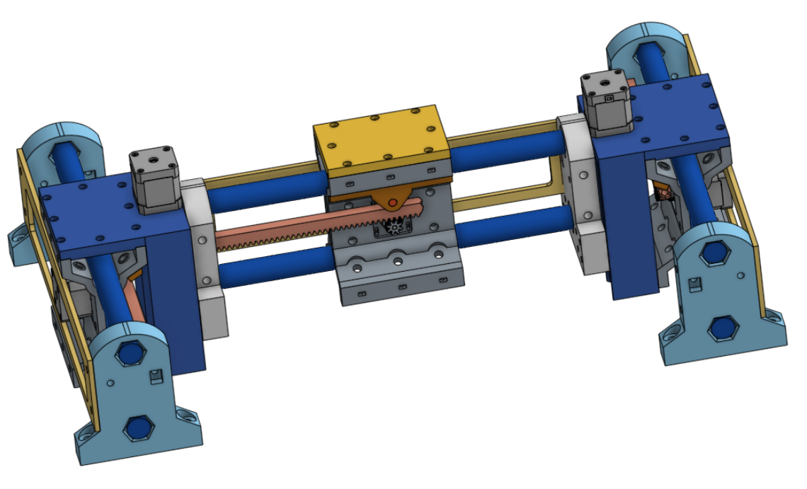
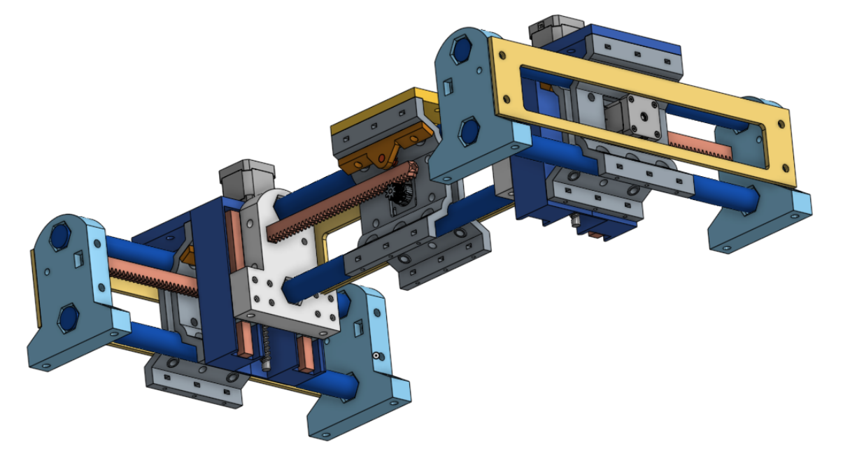
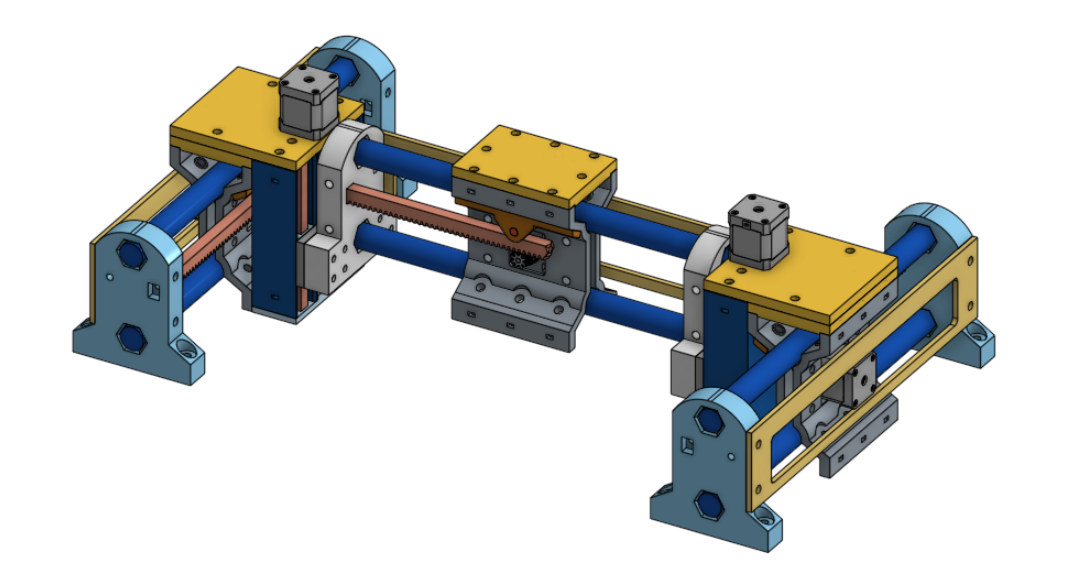
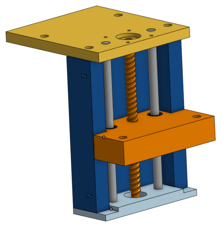
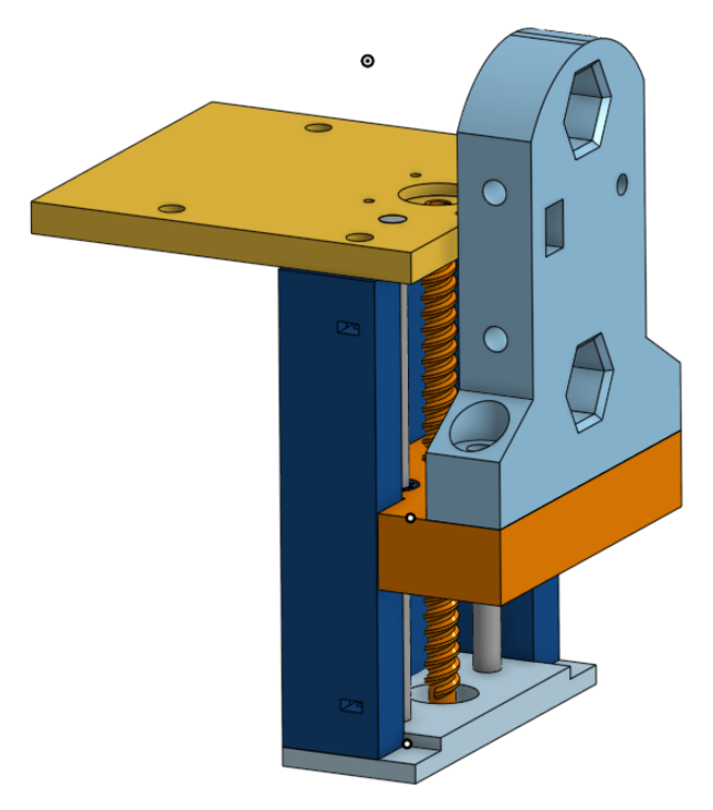
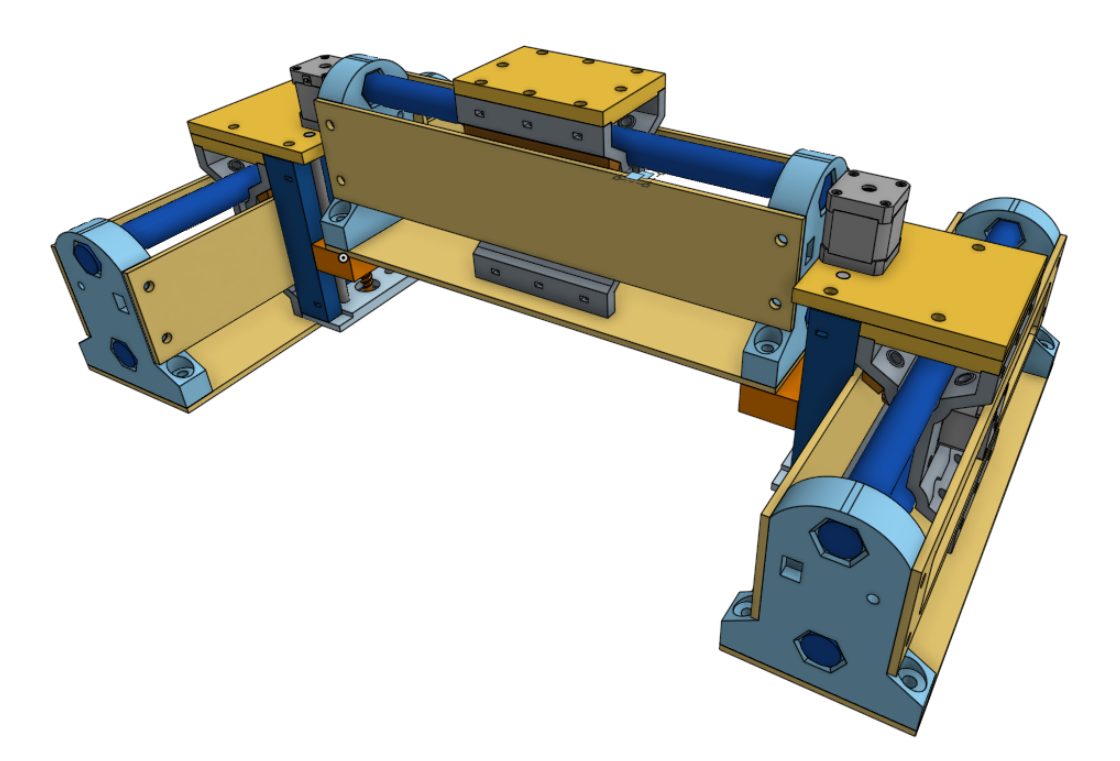
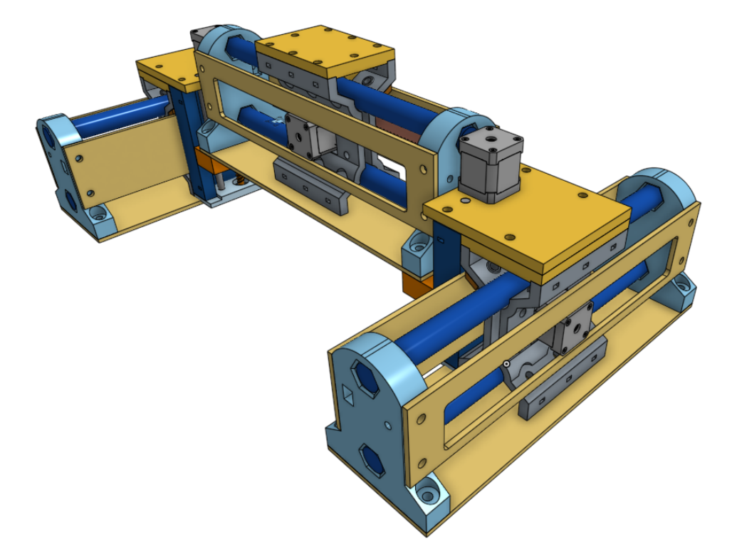
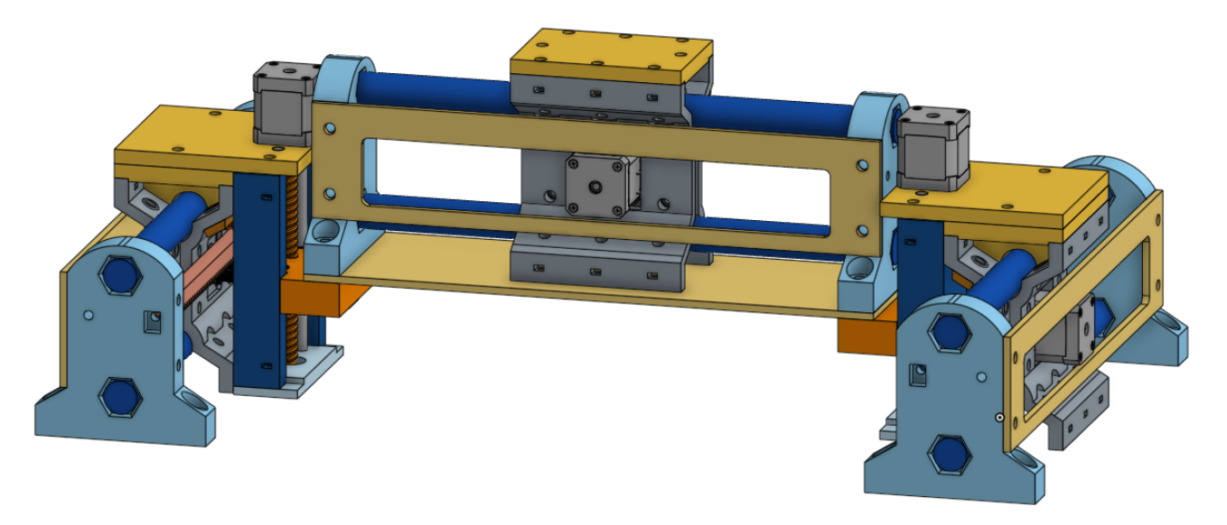
In the following renders I’m showing flat-panel plywood stiffeners in place that I think will make the whole machine more rigid but adjustments will need to be made to provide a tad more clearance between parts. I really think now that the entire machine can be virtually three identical linear stages and the two Z-lift assemblies. All that would remain is a fixed-position tool mount on the gantry’s X-carriage… which I envision would mount similar to the lift assemblies on the Y-carriages.