That’s up to you. You can print as many rack sections as you want, you can buy 1/4" (6.35mm) threaded rod in 36" (~914mm) lengths and longer. And 3/4" EMT is available in the US in 5’ and 10’ lengths from our big-box stores.
HOWEVER, as Ryan has pointed out, unsupported lengths of 3/4" EMT will start to flex and twist as the lengths get longer.
I have not yet designed in support for the EMT “rails” on MPR&P because my builds are on a 2’ x 4’ table top… and short enough that flex and twist shouldn’t be a problem. My initial thoughts for support would be skate bearing “training wheels” attached to the bottom skirts of the carriage that run along the table top or a bottom board.
I know that has been cussed/discussed ad nauseum elsewhere on the forum. I’ve always been a “seat of the pants” (rather than “rigorous theoretical”) engineer… and I’m staying out of it.
Yes, PLA+ isn’t as rigid as PLA. But, man… I wanted to print it in it’s native color before I start monkeying around too much.
David, this machine is so much fun to build, and It’s surprisingly capable. I can’t wait to have a build up and running. I hope you have a great New Years’ eve!
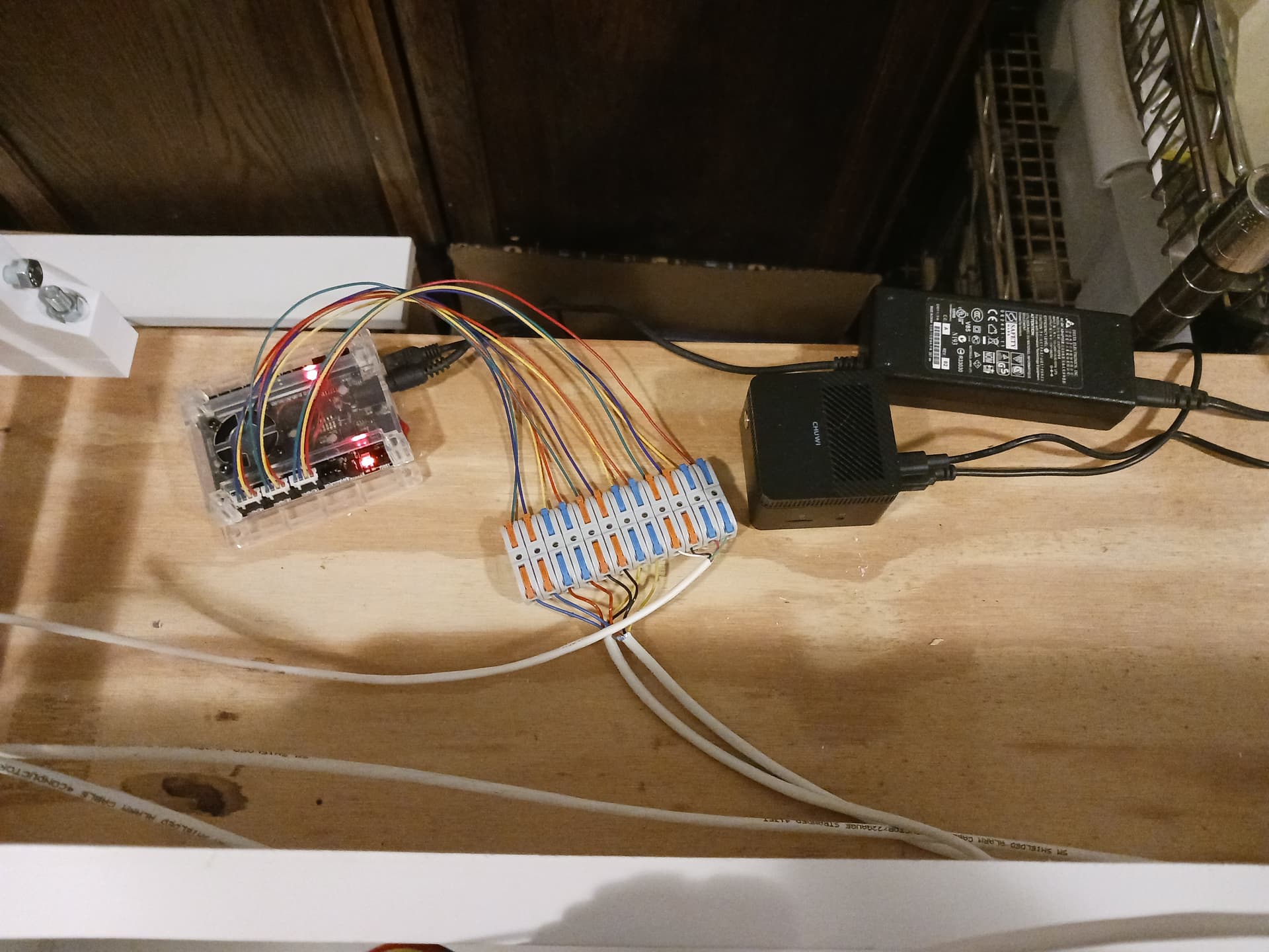
Over the next few days while I print V2 parts, I’m going to go dust of my notes about controller mounting. I had fiddled with a mount using over-length EMT on my V1 build.
That’s not really an option in the new design because the rails are captured by the carriage ends.
I’ll probably put the box on the Z axis somewhere LowRider-style, except I eventually want to be able to swap controllers between Jackpot, SKR, and maybe a board or two that I happen to have laying around.
That means some kind of temporary mount until I cut some plates. I intend to bootstrap this machine by having it cut its own plates. I may just hand-cut the Z axis plates and then mount a Jackpot V3 enclosure on it.
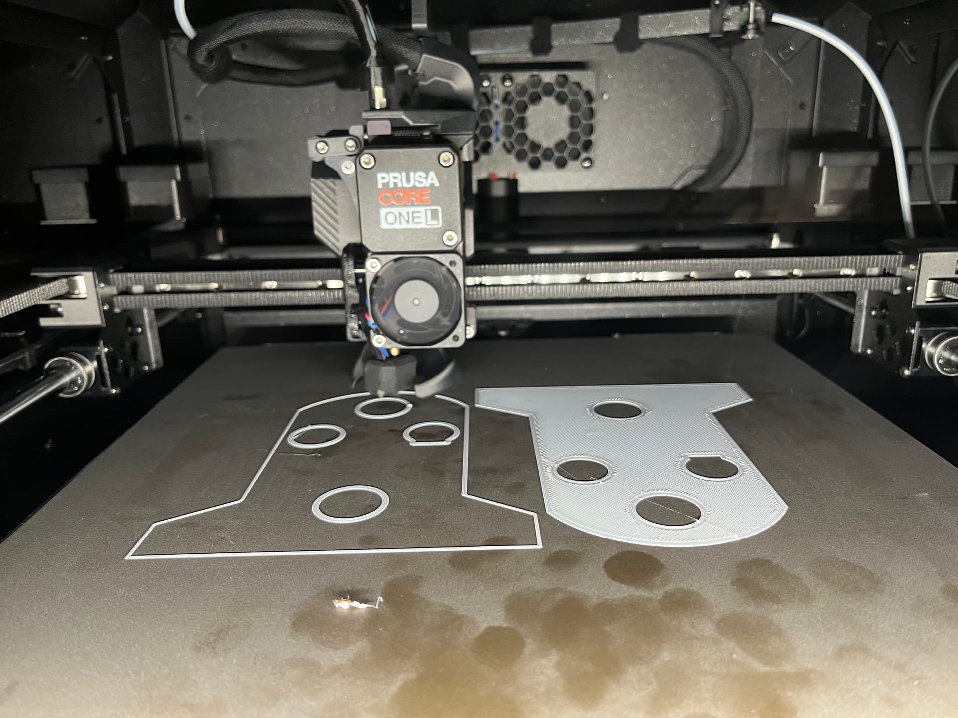
Edit to add: the filament trail is because the Core One L gets nervous and parks the print head if you open the door. I was going to flick that PLA snotball off that you see in the foreground.
I got annoyed with not being able to quickly open the door to remove a “snotball” or other – especially since I’m printing with PLA – so disabled the door settings in the settings. It also was the reason I was having so much trouble loading filament… it wouldn’t get past the side-sensor 3 or 4 inches into the PTFE tube… all while I had the door open. Closed the door and all of a sudden I was able to load filament. Too smart, I say! It is indeed “one heck of a nice printer”… you just have to play “its game”, not yours.
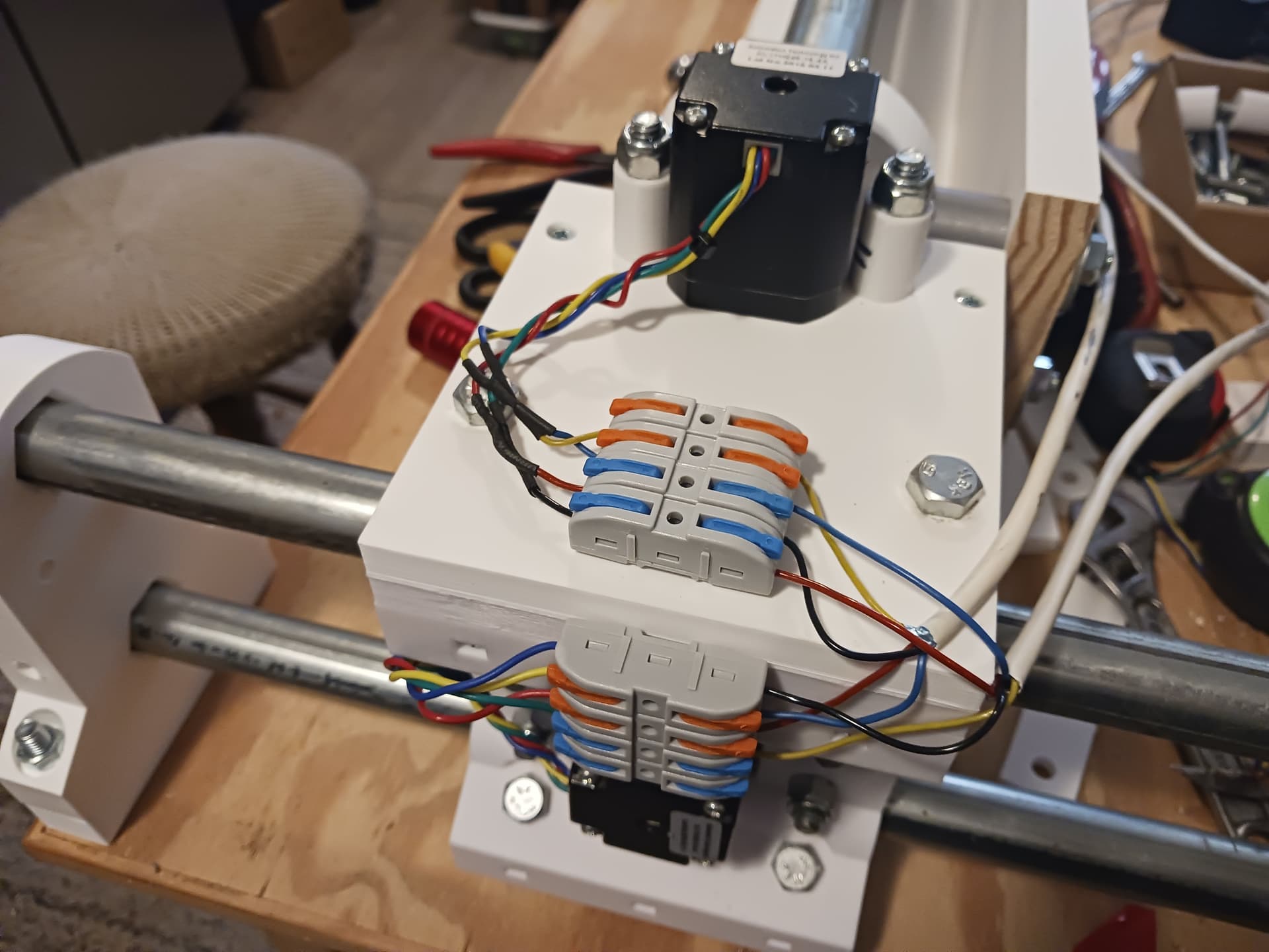
I just started following the LR4 instructions when it came to wiring and controller mounting. I was thinking a tray of some sort hooked over the back_panel/board of my gantry to hold the controller, miniPC, power brick, and maybe a power strip…
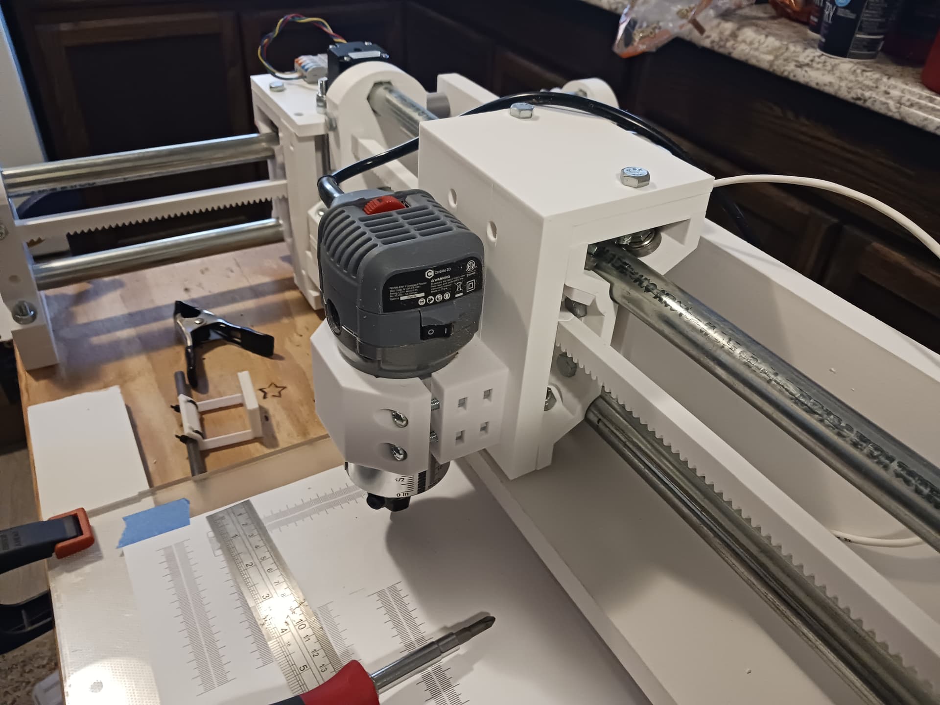
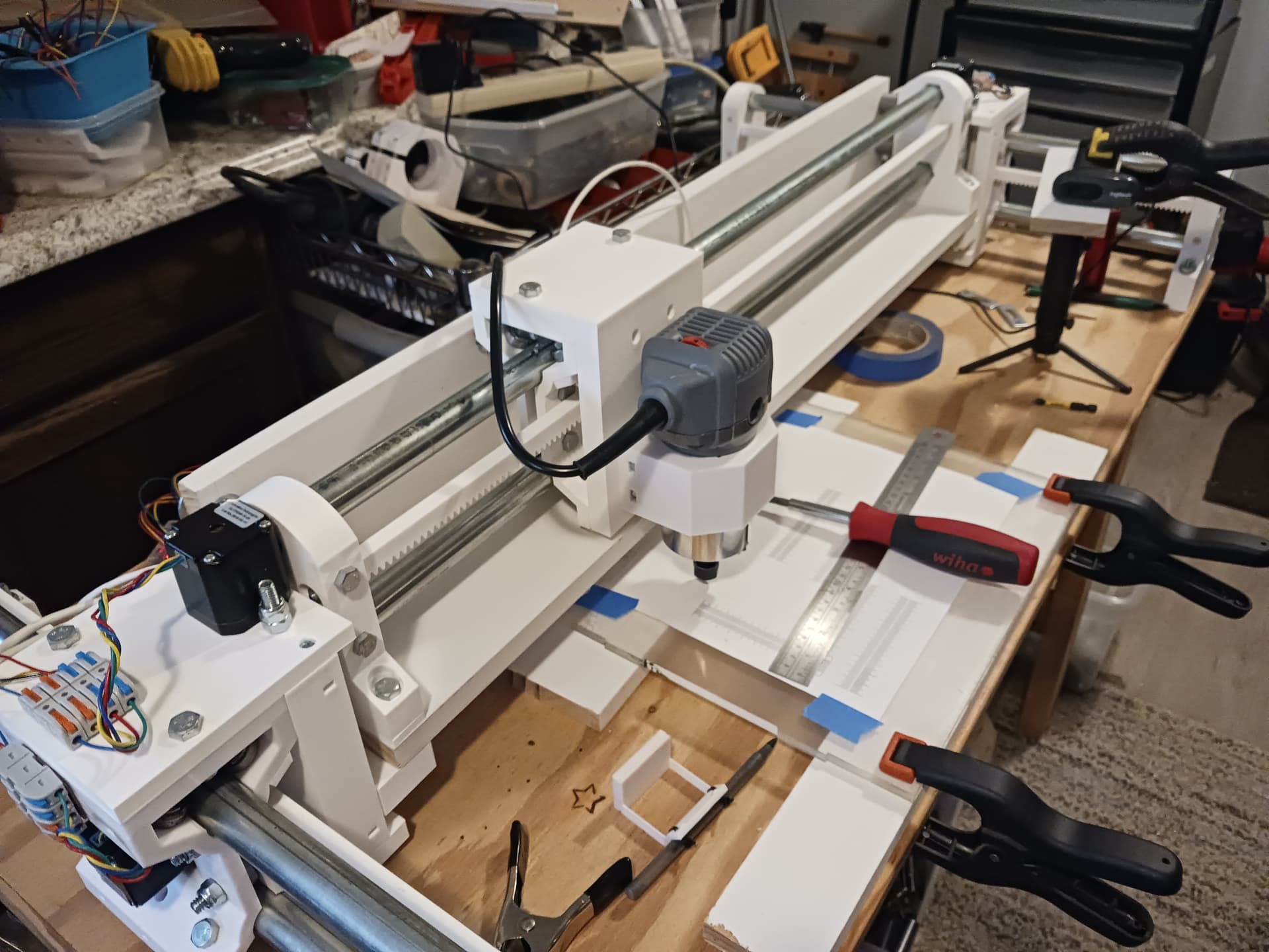
When I moved the router mount and router to the V2, I realized it probably had the ability to cut its own side- and bottom-plates. I just hate the noise and debris – with my machine in my kitchen area – but I definitely think it’s the way to go for future builders who plan to use the router anyway.
I still can’t believe you are so high on this machine… I’m so flattered. I’m honored to think that some one who has stuff flying around in space thinks this machine is worth building. Who’d a thunk it?
It’s doing great so far. Yes I’ll grab some IPA and clean it after this set finishes
Yep. Damned greasy fingers!
I should have ordered a 2nd sheet, it’s on my list for when I order the INDX upgrade this year.
I couldn’t figure out how to order one with a .6 nozzle, so it still has the .4.
It’s printed everything I’ve thrown on hit with no hiccups so far. Even with a smudged up build plate.
I’m just a fellow maker. All the V1 family of machines are extremely accessible for a newbie to make and use. MPR&P is right in the family there. Love this machine.
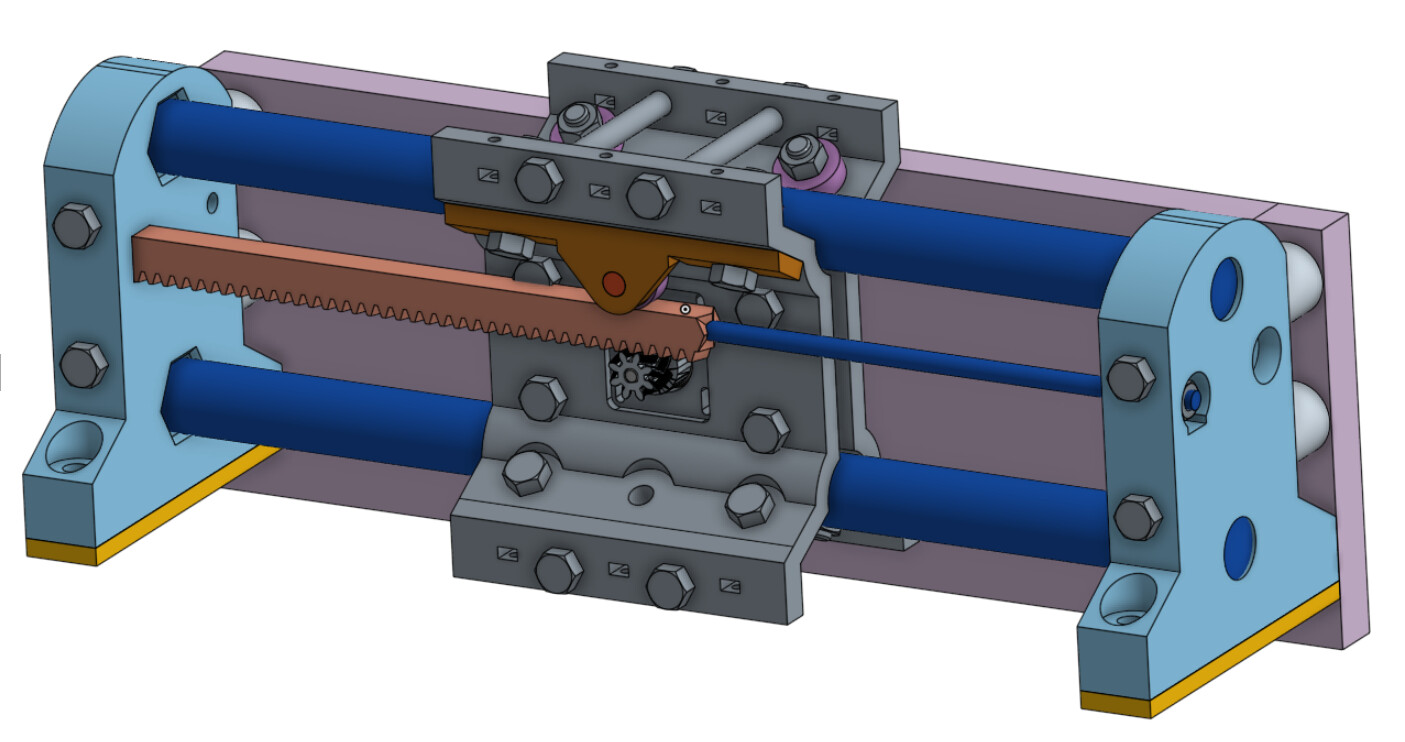
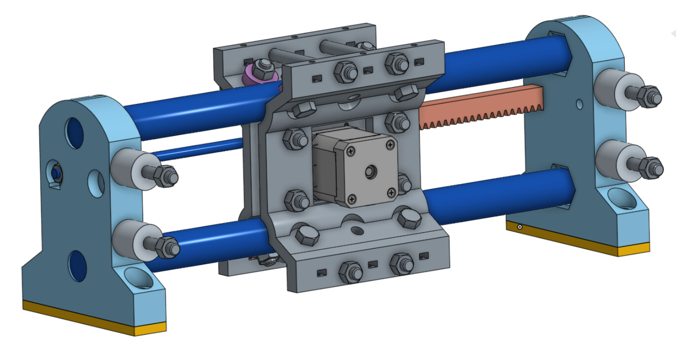
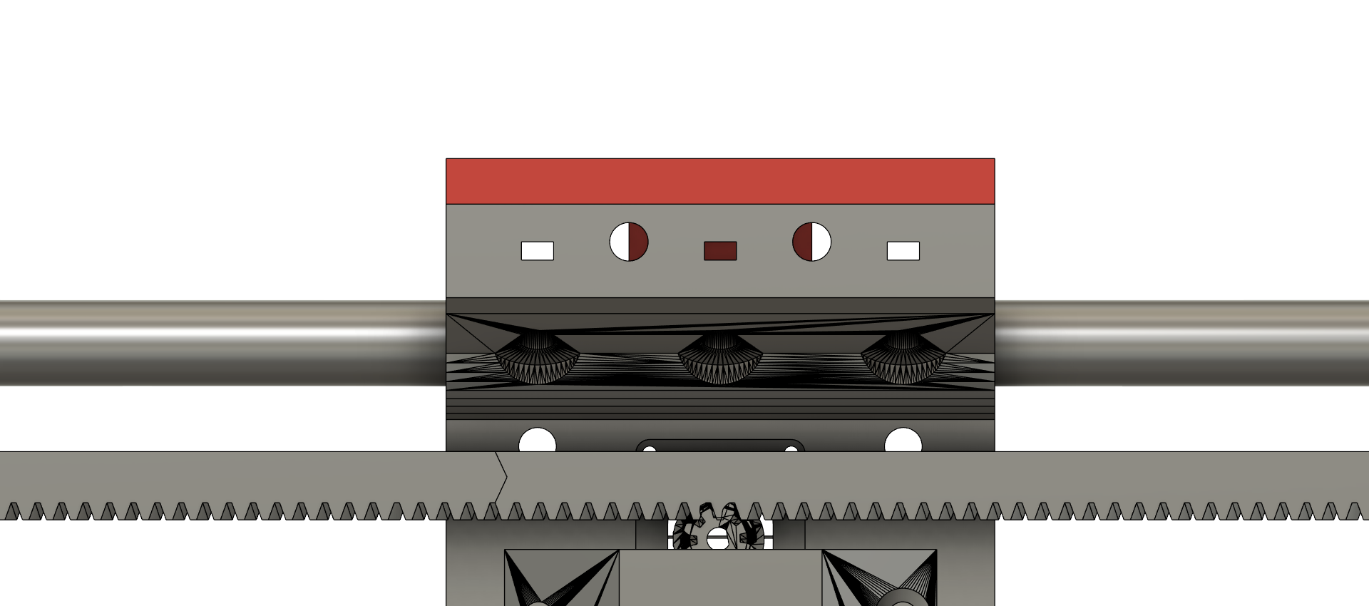
For you guys who are building, or maybe thinking of building, a MPR&P-V2 linear stage (carriage)… here are a couple of screenshots that should help with the hardware installation…
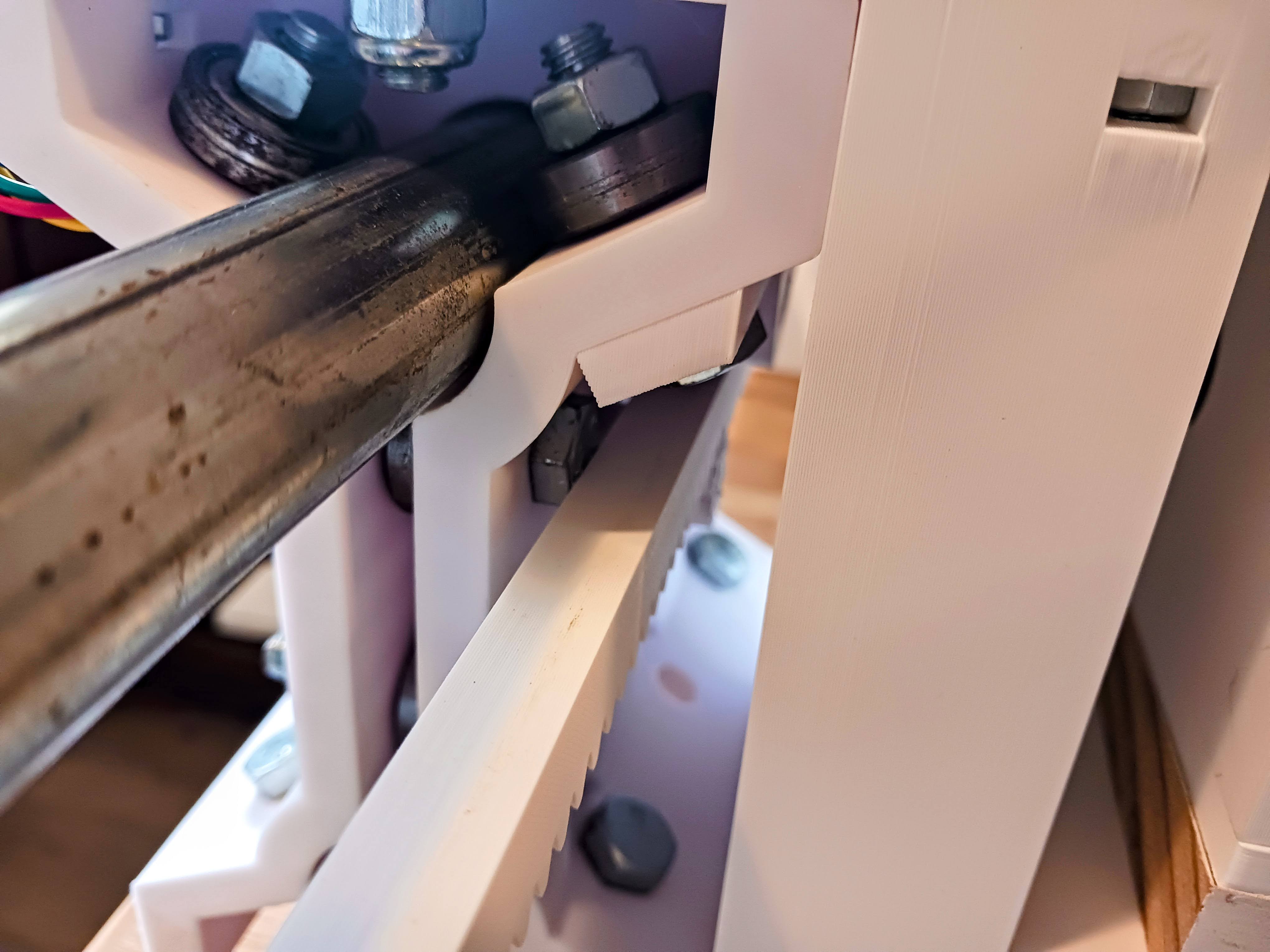
Note that the 4 bolts in the center of the carriage assembly should have their heads on the rack-side of the carriage, as there is very little clearance between the two upper bolt heads and the rack. Though this screenshot actually looks as though there is interference, the bolts I got from Lowes had thinner heads than the bolt CAD model shown here… and there was no interference in my build. If your bolt heads are too thick and interfere, you’ll probably have to grind off a bit to clear on the two upper bolts. Here’s how close mine are…
Also, the four cross-bolts shown in the screenshots that tie the top and bottom “ears” together were originally intended for mounting tooling plates… but I’m really beginning to think they’d better serve to adjust the bearing to conduit contact and take any slop out of the carriage due to bearings that aren’t properly contacting the conduit. I have had a little wiggle on a couple of carriages with bearings not in proper contact with the conduit rails. As a result I probably will need to modify the “carriage_cap” part a bit to allow the upper-most cross bolts clear passage to the opposite ear and allow the ears to be drawn together slightly during adjustment.
EDIT: I modified the “carriage_cap” and replaced the one out on Printables.
I’m using 5/16"-18 hex bolts throughout… 8mm bolts are good, too. The four central bolts are 1.5" long and capture a 608 bearing between the carriage halves. Six of the eight bearing bolts on the slants should be 1" long… the other two also go through the pressure bearing mount and are 1.25" long. The four cross-bolts, if used for bearing-to-rail adjustment, would need to be 3.75" long. The pressure bearing is mounted on a printed pin (print horizontal with support) press-fit into the pressure bearing mount. The bolts for mounting the 17mm back-plate on my machine are 5" long.
EDIT: All these bolts should terminate in 5/16"-18 Nyloc nuts.
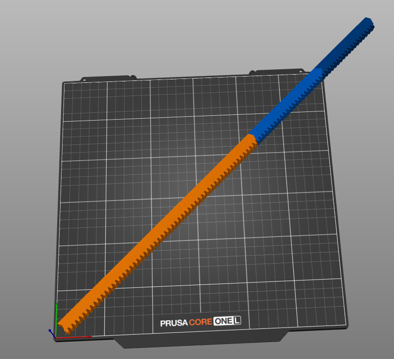
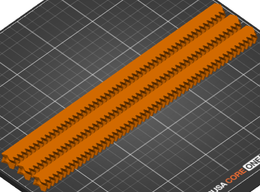
There should be thirteen 608 bearing total in the carriage assembly. The 1/4"-20 threaded rod that goes through rack segments will vary in length with how long you make your linear stage and ideally shouldn’t extend beyond the surface of the end supports if you want to keep a clean/flat end-support outer surface.
You grabbed these at Lowes? I’ll head there to grab some for my build.
Let’s see if I was paying attention
Per axis:
1.5" - qty 6
1"- qty 6
3.75" - qty 4
5" - qty 4
What about the Z lift bolts/(Pseudo rods)? What length bolts are you using there?
The pinion and racks are the same. I did put a 56-tooth rack segment out there as the new printer could handle it (40 -tooth was the largest I could do on the MK3S). Print the racks on their side.
It might be easiest to just print the longer ones and then chop-saw the end segments to get flat ends to go into the rectangular end support recess and get the exact length you need.
I probably could have eeked out a bit more but I was building a fairly small machine and didn’t mind using 2 or 3 segments… and the seams don’t seem to be a problem. I envisioned printing an entire plate full of rack segments at one time…