I have a box full of old 3D printer leadscrews and lead nuts, pulled from various things I’ve decomissioned over the years. Any given user could very well be in the realm of junkbox build if they have any older 3D printer parts on hand or even with a $10 internet junk purchase of a dead 3D printer.
3 Likes
Yeah, I’ve got a couple of old 3d printers and leadscrews and nuts aren’t hard to come by. I guess I really was thinking more of the linear guides when I wrote that… ![]()
1 Like
I chuckle- in a very congratulatory/joyful way, each time I mock up the motion with the printed / bolt guide setup. With a metal lead screw and bearings I don’t see why it wouldn’t be very serviceable.
2 Likes
Ya’ know… now that you’ve reminded me of the old 3d printers I have sitting around, I’ve also got polished rod and LMxUU linear bearings to scrounge as well. That would be even better than the bolt “guide rods” and still keep the lift assemblies almost purely “junkbox” assemblies as well. Thanks for reminding me, Jim.
![]()
EDIT: A moment’s digging… found the old Mendel I2(?) A-frame printer I started with… five minutes “extraction”: two 390mm long 8mm polished rods and four 24mm LM8UU linear bearings. Perfect!

4 Likes
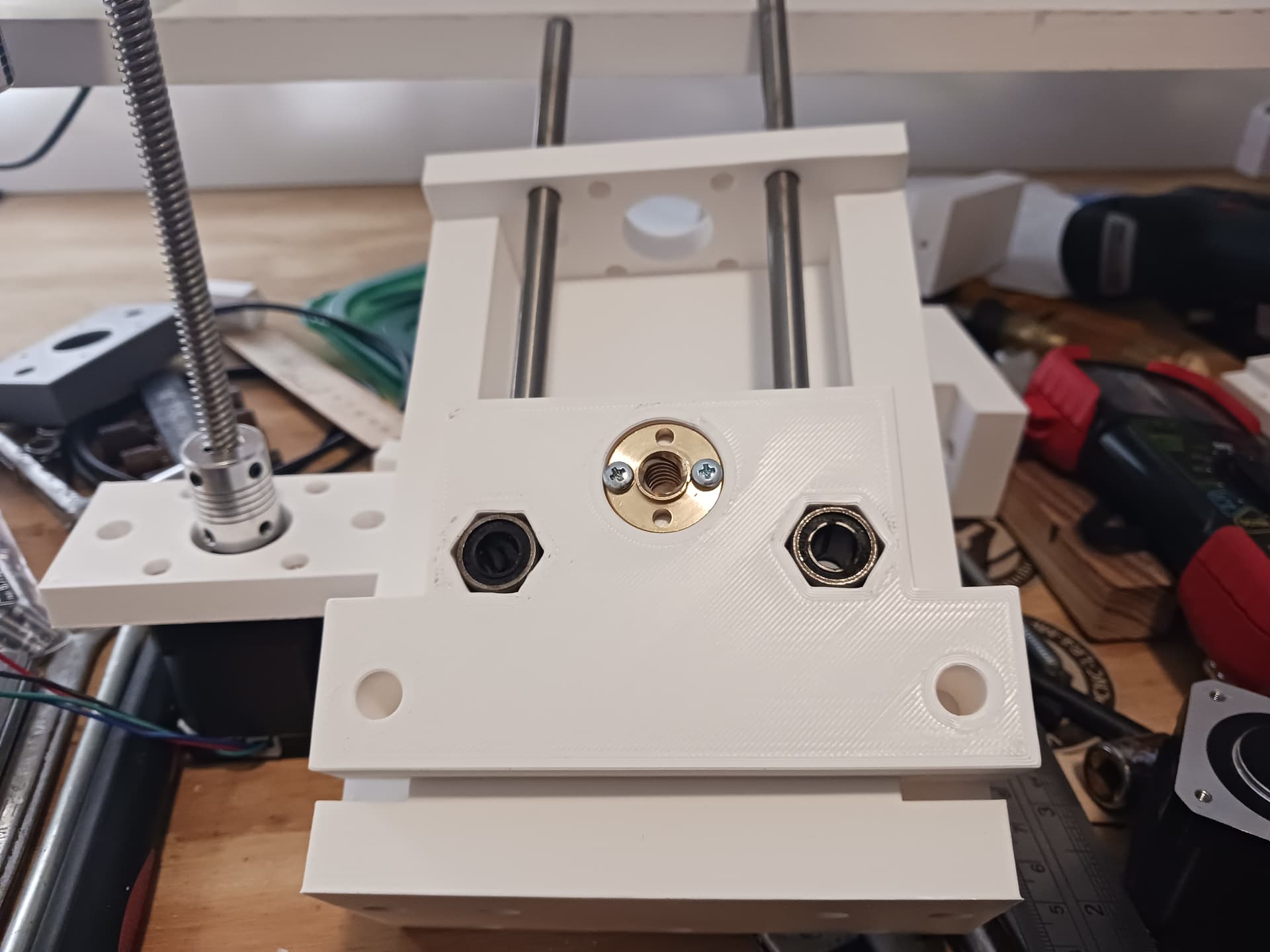
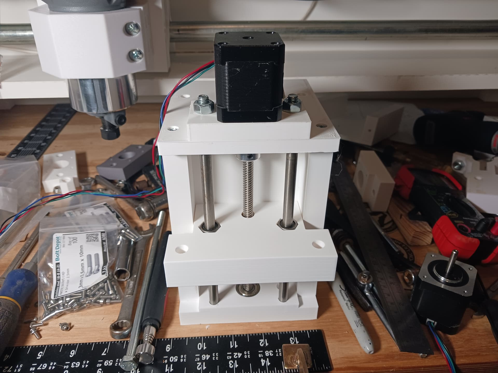
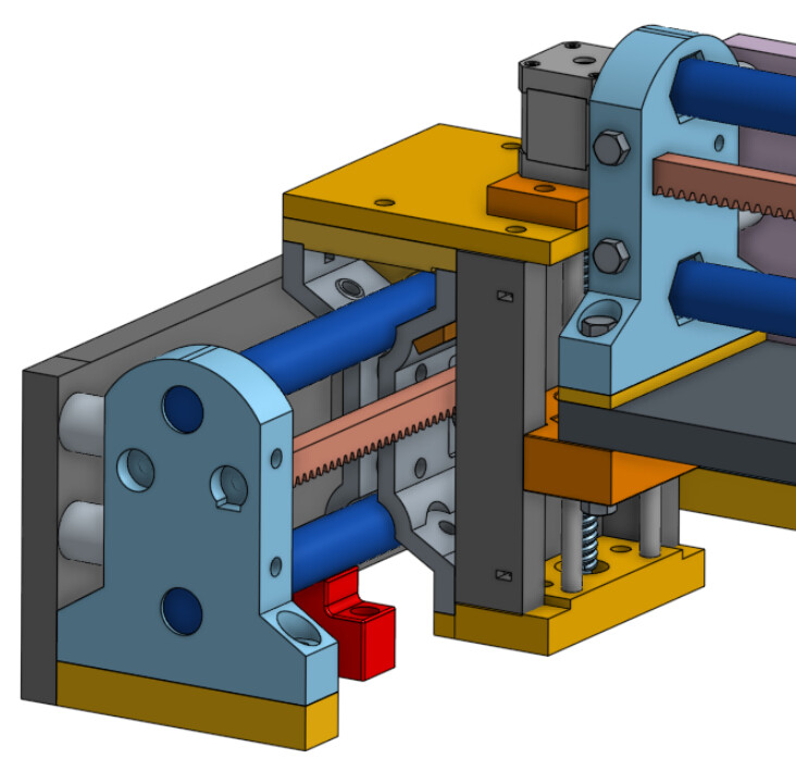
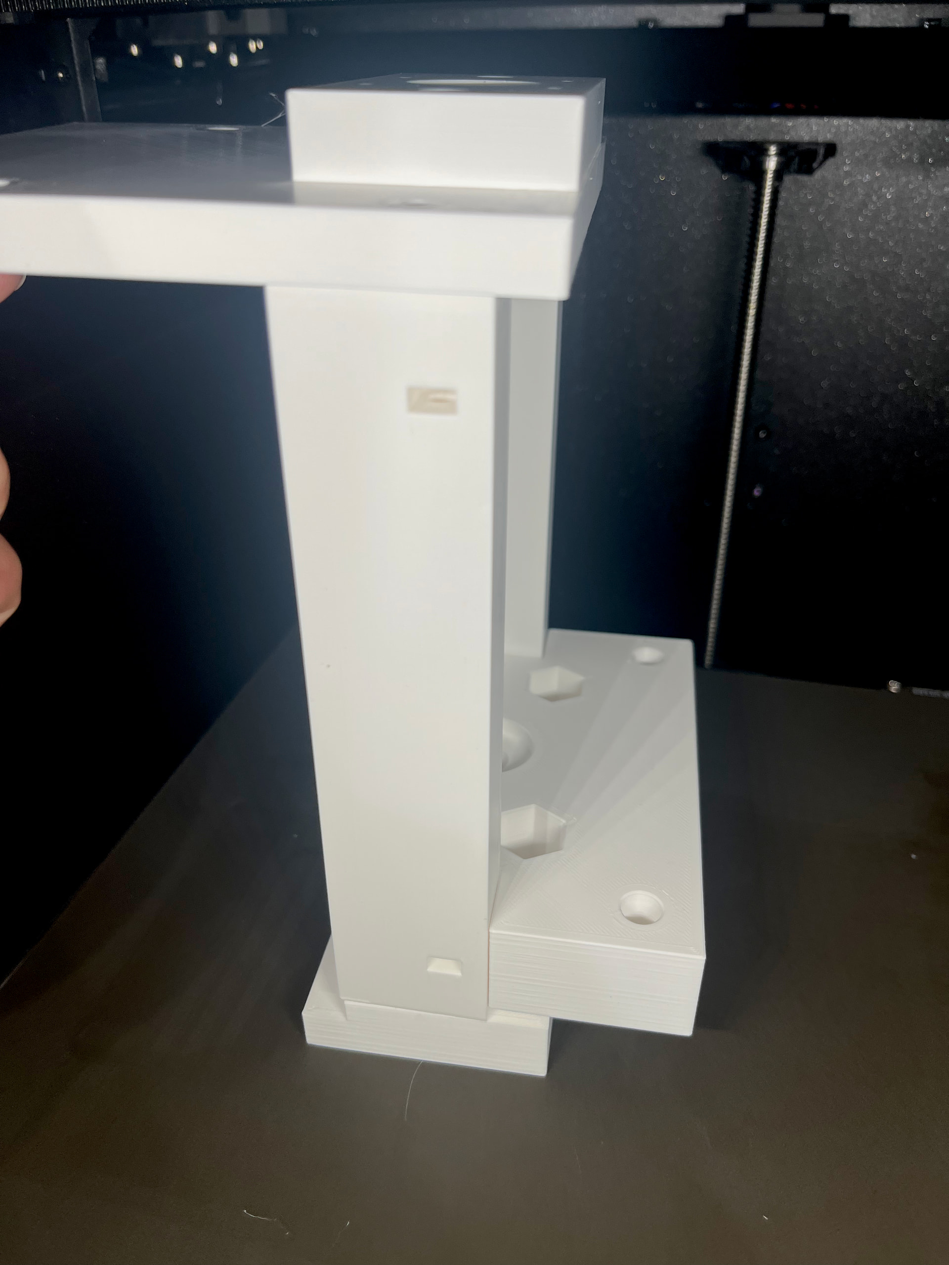
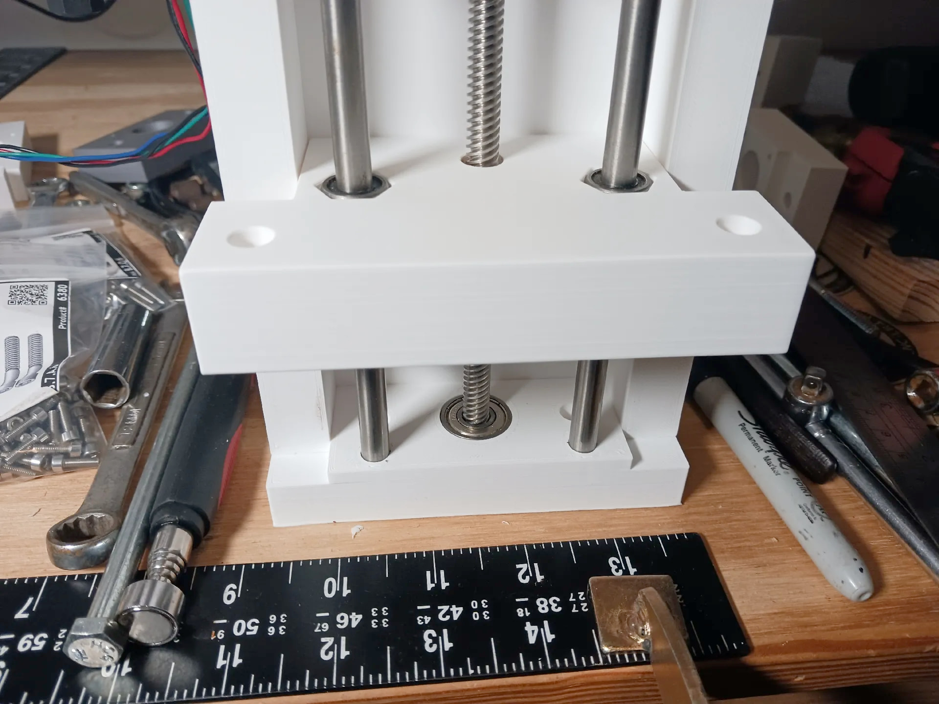
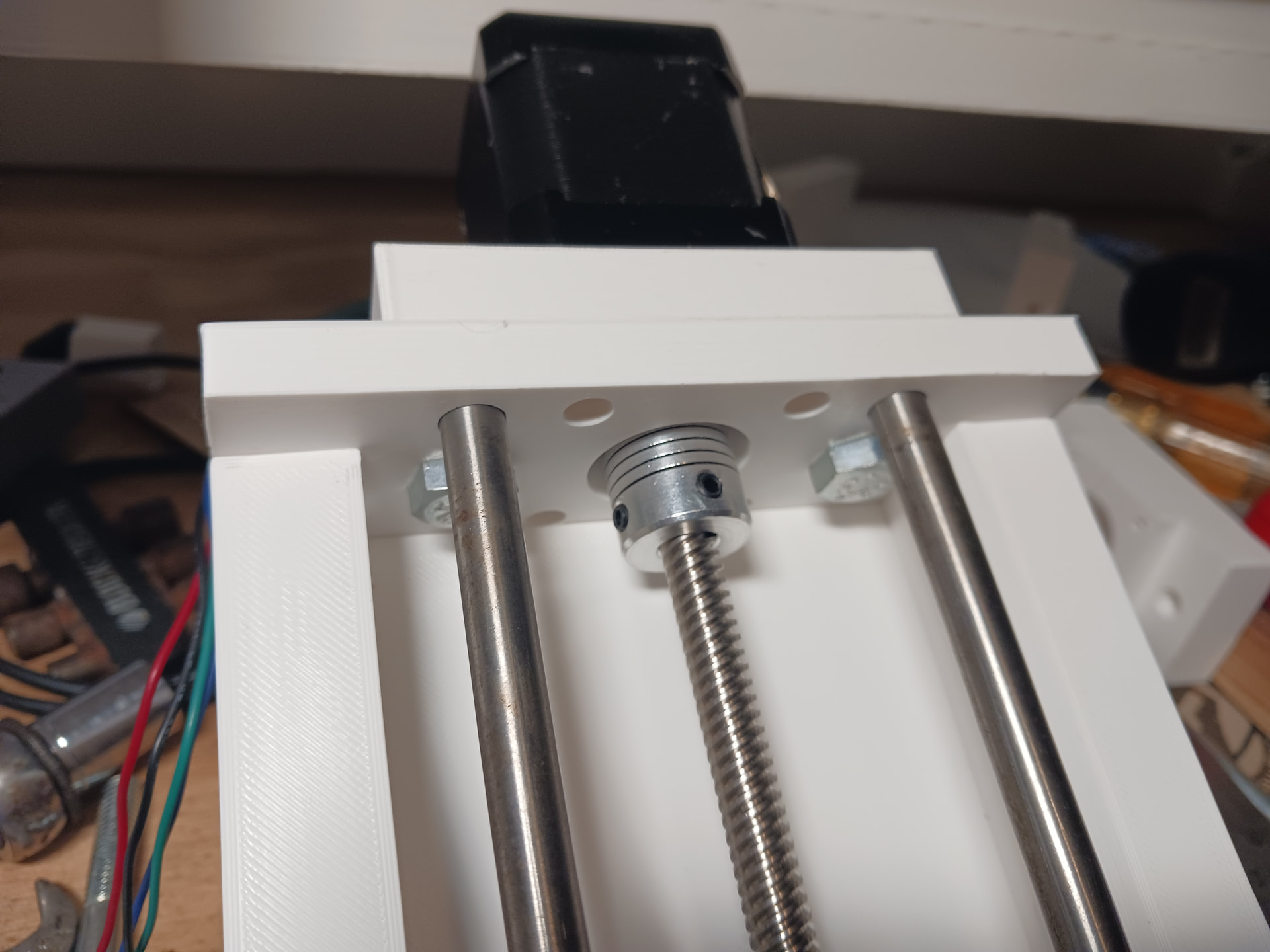
Alright, a little nip here and tuck there… and we have probably what I should have started with in the way of a lift assembly.
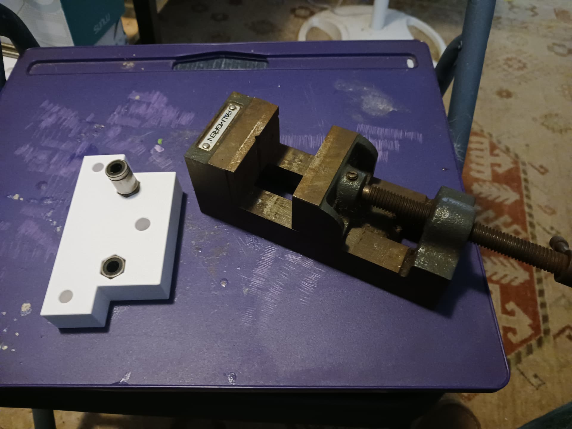
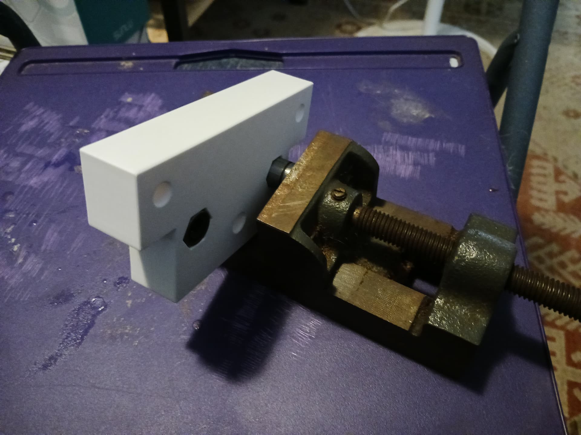
I was able to inset the T8 leadscrew nut and press-fit the LM8UU linear bearings into a new lift block with my bench vise.
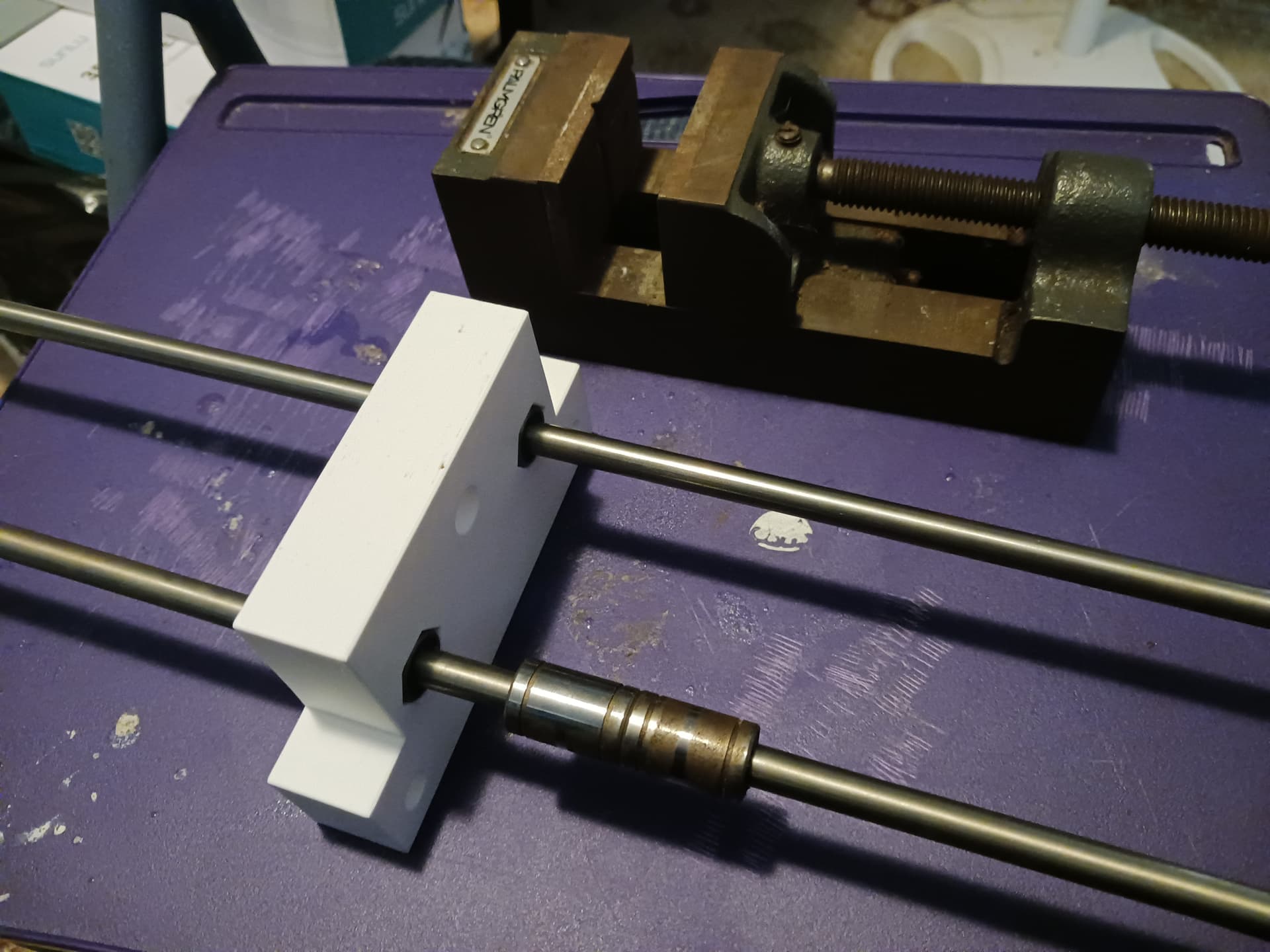
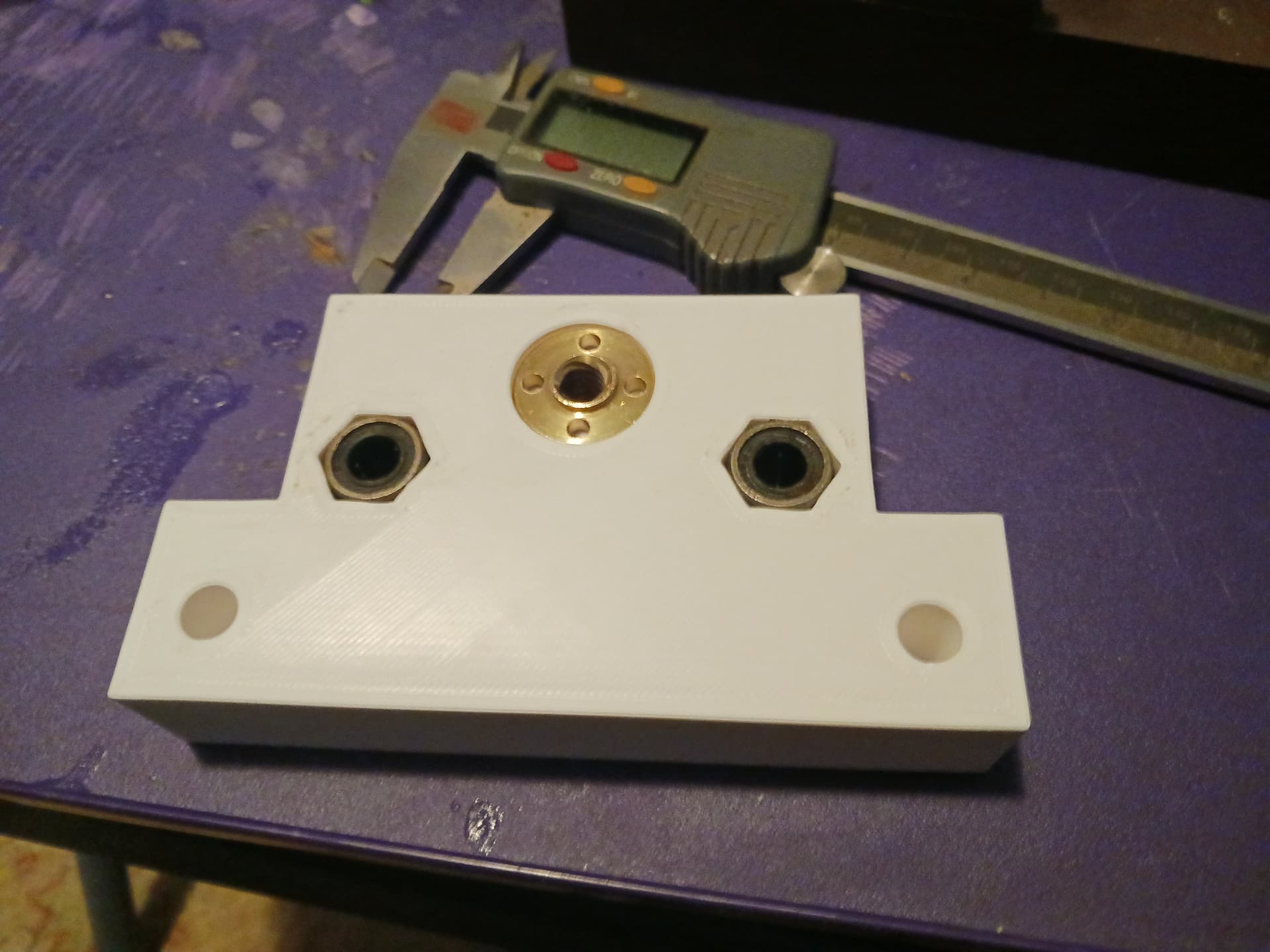
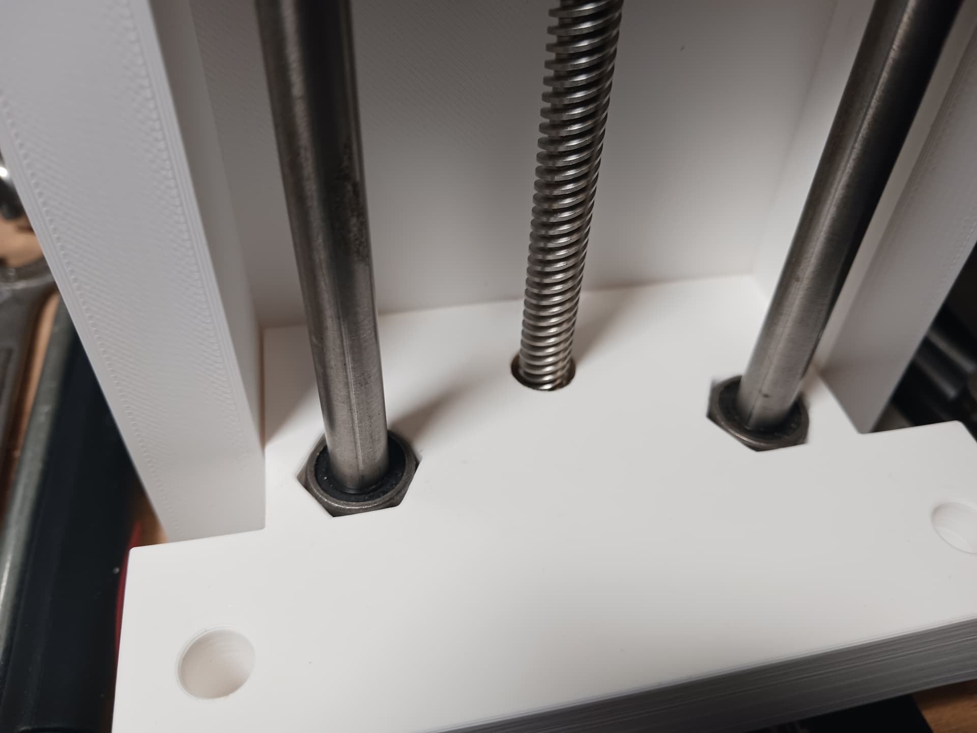
The 8mm guide rods fit into a pocket in the capture plate at the bottom end and the motor block/spacer traps them at the top end.
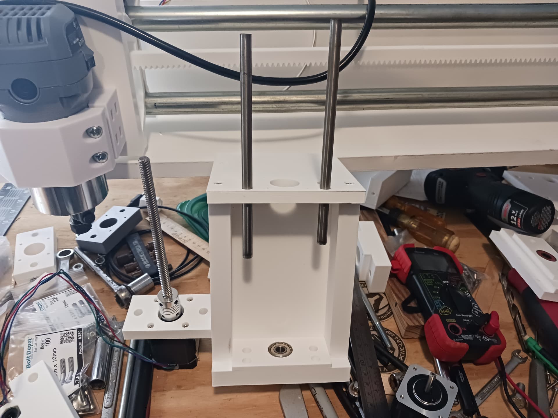

Actually, when using the smooth rods and linear bearings scrounged from an old 3d printer, it practically “forced” the design into a more stable “3-point stance”… with the leadscrew and guide rods now offset from one another (there’s probably a reason linemen in American football get into a 3-point stance… reckon?).
I’ll start printing the parts for a second lift assembly right away and hopefully be able to replace the old lift assemblies tomorrow. There are a couple of minor fixes I need to apply while I have it torn down.
Later.
5 Likes
… a right fine looking lift assembly. I’m really looking forward to this one.
3 Likes
I really think this is the way to go as well, Jim. Again, thanks for reminding me I already had the parts I needed in an old unused printer just sitting in my stash.
While I still think the printed screws are neat and might be made to work fairly well once all the trial and error is done… plastic on plastic will never be as sturdy and smooth as the tried and true metal parts. It was just taking too long to keep iterating any longer… and when I found myself going back to adjust previous attempts, that’s when it started to feel that I was just spinning my wheels.
7 Likes
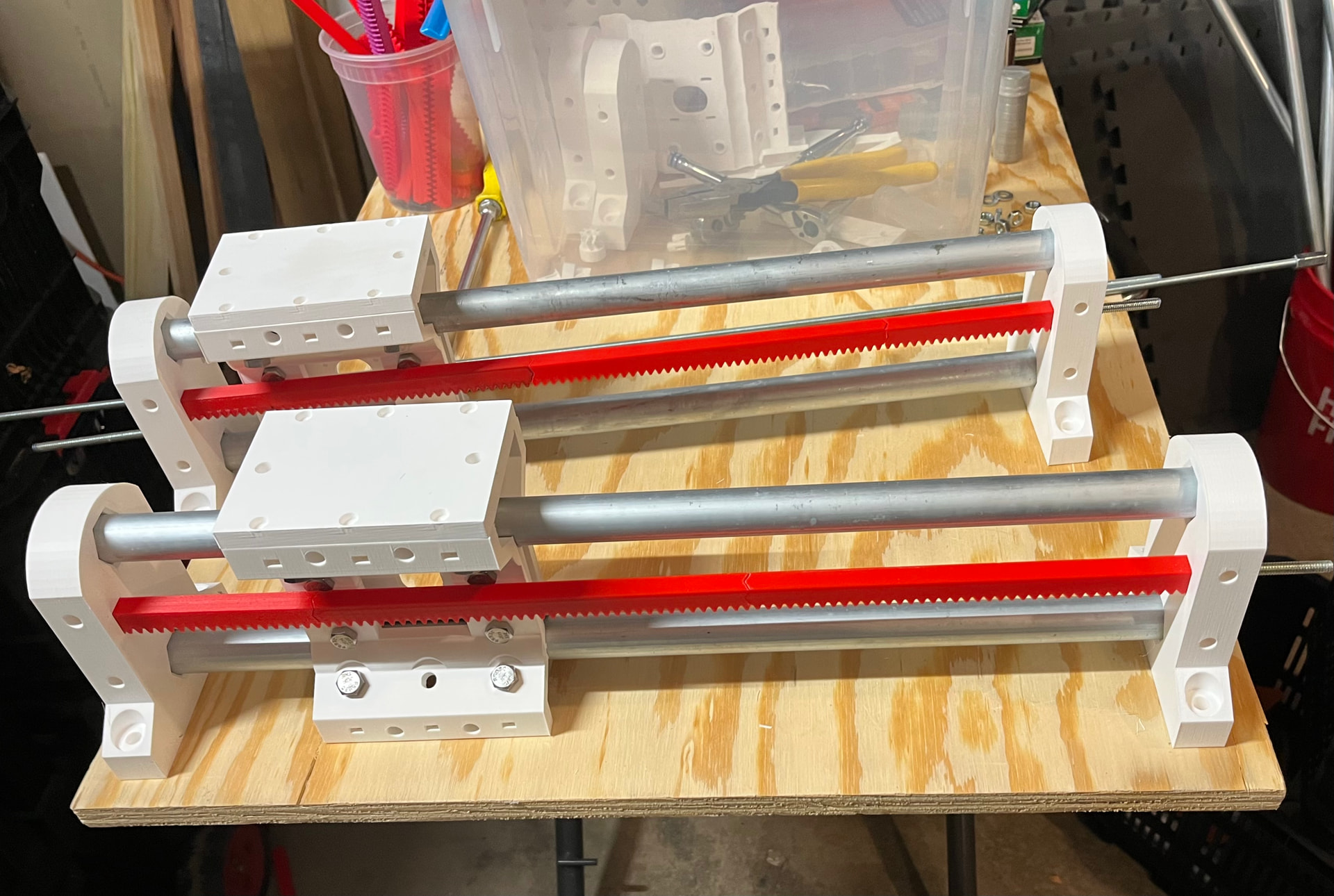
More progress…
I built up and installed a second T8 lift assembly, reassembled the machine, and have air-milled a number of fairly lengthy jobs without any discernible loss of steps or level in the lift setup. I plan some further testing but, all in all, I’m now pretty happy with the MPR&P-V2. I’ve updated Printables with the latest printed parts and feel confident that a workable MPR&P-V2 can be built using those parts, combined with relatively inexpensive and readily available hardware and paneling from local stores, online sources… and, maybe, even your junkbox or stash.
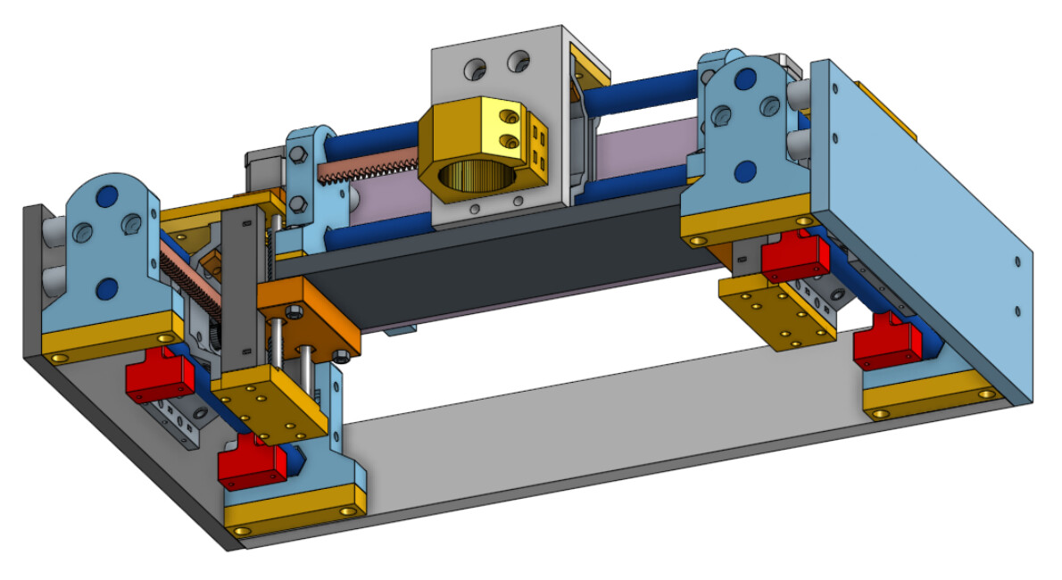
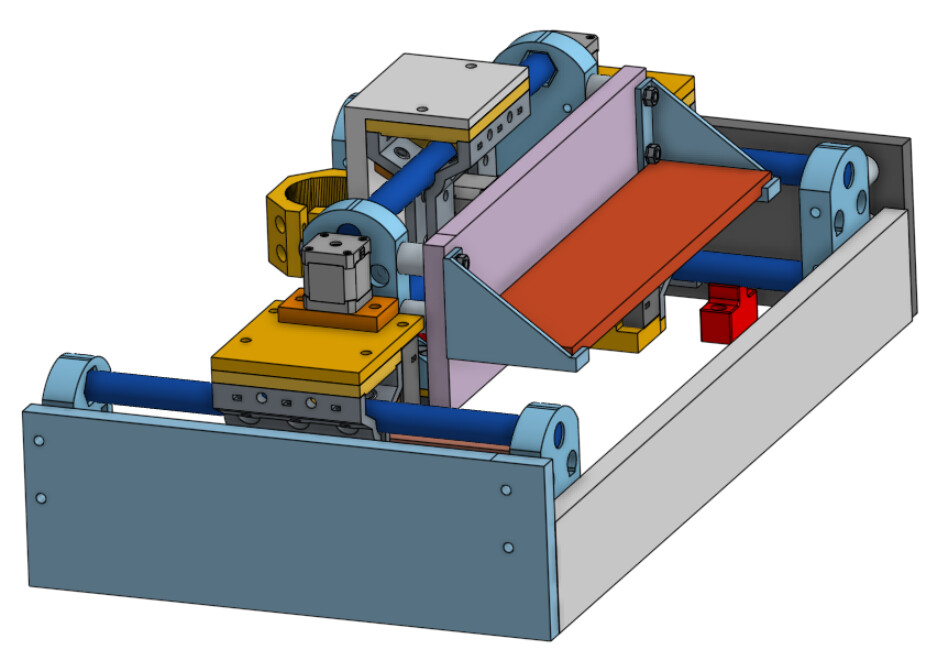
As you can see, MPR&P-V2 has morphed into a partially-enclosed machine… if you choose to add the side and back panels as seen in these renders. I envision a removable panel for the front with printed hooks that hang over the front side-board spacers… and allows for loading material and setting zeros before job start.

As I’m hoping that MPR&P-V2 is in its near-complete form, I hope to start playing more with other controllers… with an eye, of course, toward replacing the little 8-bit GRBL controller currently in use. I do have a Jackpot board that I purchased from Ryan and suppose that should be the obvious choice… and one that I really need to become familiar with. I’m sadly behind the times it seems. ![]()
Later.
5 Likes
Retesting after Z-lift overhaul to using metal T8 leadscrews and 8mm polished rod and LM8UU linear bearings from discarded 3d printer.

All went well and I’m satisfied this is the way to go on the Z-axis. No discernible missed steps over faily lengthy jobs and accuracy similar to prior testing.

Later.
8 Likes
I have started printing the updated Z lift parts.
6 Likes
@dkj4linux - checking in.
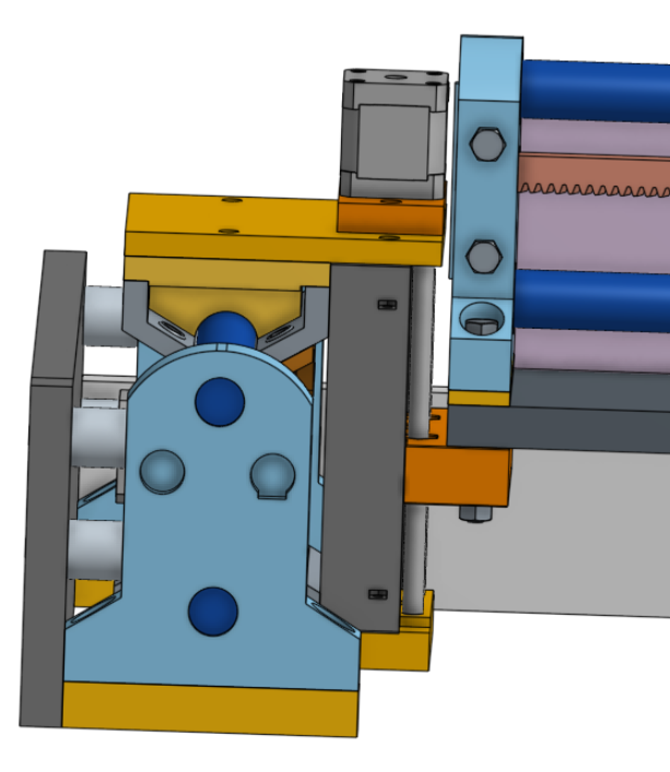
Here’s a mock-up of the new Z lift parts. The Z lift body has a new file date, but I can’t find any changes in the slicer and the old body seems to still fit the new parts. Did you change anything in it?
If folks zoom in, you can see the Core One L has developed some Z banding in the parts this week. I’m going to re-tune it. That has me bummed out.
Mid-week last week it did this:
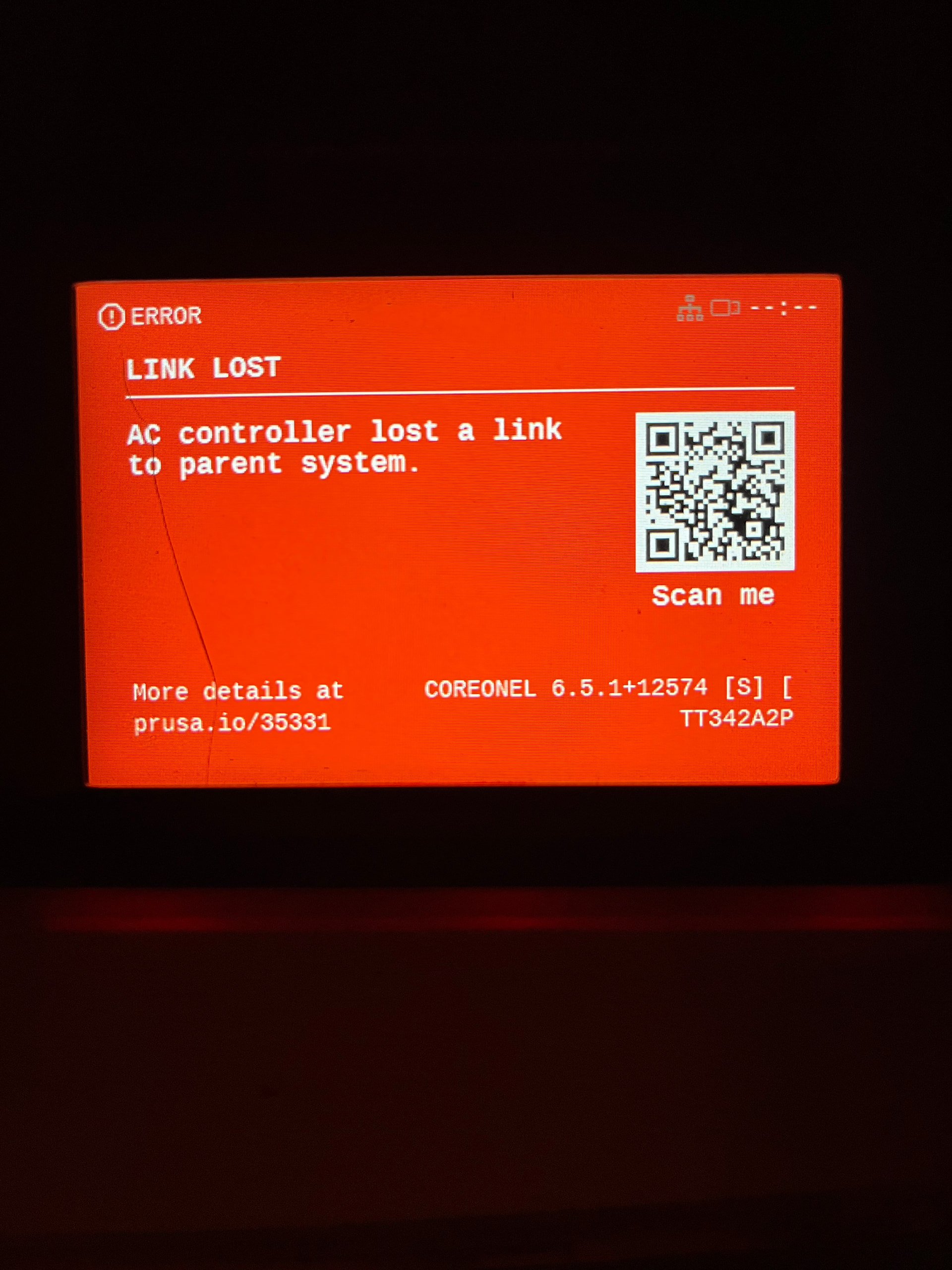
Printer was sitting idle between prints and started beeping incessantly. No power hits or other glitches I know of.
After I rebooted the machine, it had has been OK. Damned confusers… as my dad used to say.
Z banding was there before and after the printer brain fart. The QR code error message link is a nice touch. The brain fart isn’t.
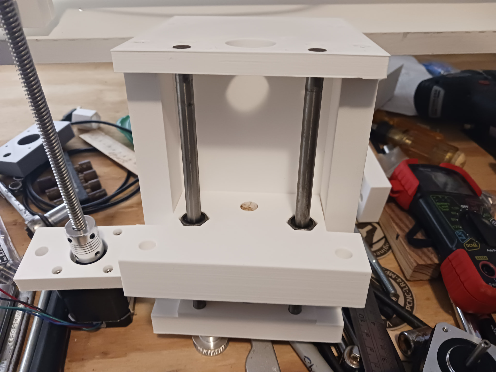
Most all the Z-lift parts are dimensionally the same as they were… just with a few more holes. The body/chassis (gray part) stayed the same… the bottom capture plate, the lift block and cap/top plate all accommodate the relocated 8mm guide rods, and the motor spacer is new. The screw in this render isn’t the LR4 leadscrew that I wound up using… but is properly located.
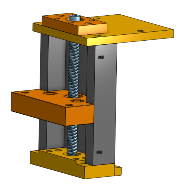
Post #226 pretty much shows how I assembled it. It can be assembled pretty much from the top, thankfully… so once the lift assembly is attached to the Y linear stage you shouldn’t need to get to the bottom screws. Press in the LM8UU linear bearings and inset the leadscrew nut into the lift block. Put the coupler roughly into position of the motor shaft and then attach the new motor spacer to the motor. Assemble the capture plate, chassis body, and cap plate with M4 screws/nuts… make sure the 608 bearing and a BB are in place on the capture plate. Drop in the leadscrew, making sure it sits on the BB under the bearing. Drop in the guide rods to sit in the recesses in the capture plate and insure they are about flush to the upper surface of the cap plate. Then put the motor/spacer/coupler into place, feeding the coupler onto the leadscrew and then tighten those grub screws. You may have adjust the coupler to share the motor shaft and leadscrew a time or two… but I think it most important the leadscrew sits firmly on the BB.
I don’t get the prettiest prints off my CoreOneL either. I think it may be a combination of using the wrong filament (I’m using Sunlu PLA now… not PLA+) and me adding perimeters, adjusting infill, etc. away from the Prusa’s presets. I have seen significantly prettier surfaces when I use their STRUCTURAL presets without me jacking with them… but I’d rather have stronger walls and denser infill than the presets provide. So I’ll live with the crappier surfaces for now. I have had to reboot a couple of times to clear an error or lost connection… but everything resets okay. I was a bit surprised that it takes so much longer to map out the build plate with each new job… and it seems “unprofessional” the way it comes to the front right and beats its head in the corner, loudly and for longer than I would think necessary. But once it gets going… its nice and quick compared to my MK3S.
I’ve got lots of photos from my build. If you have questions, holler… and I can probably show photos of the way things stack up.
1 Like
I figured that one out. It’s… Opening the top vent (with PLA) or banging it closed (other filaments) clever but: Why not just use a motorized vent?
Doing some mock-up of the assembly.
I’ve decided that the donor for the first, small MPR&P is going to be a printer, in honor of the scrap box theme. I’ll start teardown of one of the older bedslingers shortly.
Questions for @dkj4linux -
You probably said this, and I should have noted it but- what size screws are the carriage caps designed to use?
You also probably said this- for the carriages, the bolts that join the halves are very close to the rack. I think you mentioned finding thin head bolds. Is that true? Mine allow movement, but it’s very tight- .1 or .2mm of clearnce. I’m going to look for thinner head bolts and am considering a remix to make an isert.
Also, on the carriage halves, the relives the other bolt holes have would be a welcome addition. The bolt heads bind up on the body at the very end of tightning them.
Hopefully more pictures later.
4 Likes
I believe that I’ve used M4 screws throughout… except for the M3 screws that mount the motors.
The 5/16" bolt heads holding the carriage halves are indeed very close to – but clearing – the rack. Some of the 5/16" bolts I’ve gotten from Lowes over the years have very slightly thinner heads than others… different batches/vendors I suppose. I’ve never worried about it since the thinner ones did barely clear the rack and, if necessary, I figured one could lightly grind the bolt heads thinner for any additional clearance needed. Also figured the rack – being in fair tension – should remain straight, centered on the pinion gear, and also clear of the bolt heads.
Feel free to remix but not sure what the “isert” is… insert, inset, other? Also, I pretty much ignored putting any washers/bosses/etc. in place on the prototype to protect the plastic as the bolts are tightened… I just snugged things up as much as I dared and used Nylocs where I was afraid things might loosen with use.
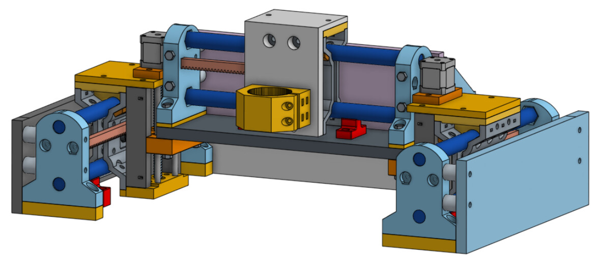
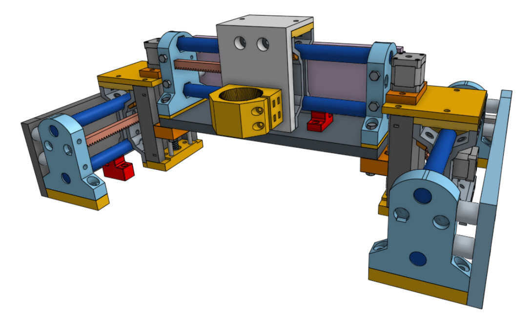
I love the red racks. It seems fitting that the R&P in MPR&P should be emphasized and shown in stark contrast. I also don’t know whether you have bearing in place yet in your mockup… but the angled bearing bolts should ideally be 1" bolts (except the 1-1/4" ones that also go though the pressure bearing mount)… but if not, at least reverse the lower ones to put the heads next to the bearing for clearance of any rail supports, should they be installed on a longish linear stage. These rail supports are shown in red in this screenshot…
I’m sure there some adjustments that could/should be made to ease assembly… but of course I was just trying to get things crudely held together while testing for proper function during development. But being as modular as it is, I was also able to see pretty consistent fit and function between units… so I didn’t think it too bad for a DIY “one-off”.
Obviously I wasn’t too mindful at the time of how non-intuitive or difficult it might be for someone else to figure out how to assemble it. I therefore dub thee…
“Jim, Chief Guinea Pig”, in charge of Production.
Have fun!
![]()
5 Likes
That’s exactly my plan- it’s the color which just screams “Look at me! Look at me!”.
Sweet, I should have a bunch. You used M4 square nuts for the nut traps?
The angled ones are 1". I’m using 1 1/2" for the four bolts through the carriage as the 1" don’t protrude far enough.
I have another question set:
In your pictures from Printables:
and

The bolts that form the rod for the bearings to ride on is shown with the lift assembly sitting flush on a table. The nuts that secure the bolts are up top on the motor lift block. That means the hex heads for the bolts have to be recessed into the bottom block. There’s no such feature on the part released on printables… How did you put this together?

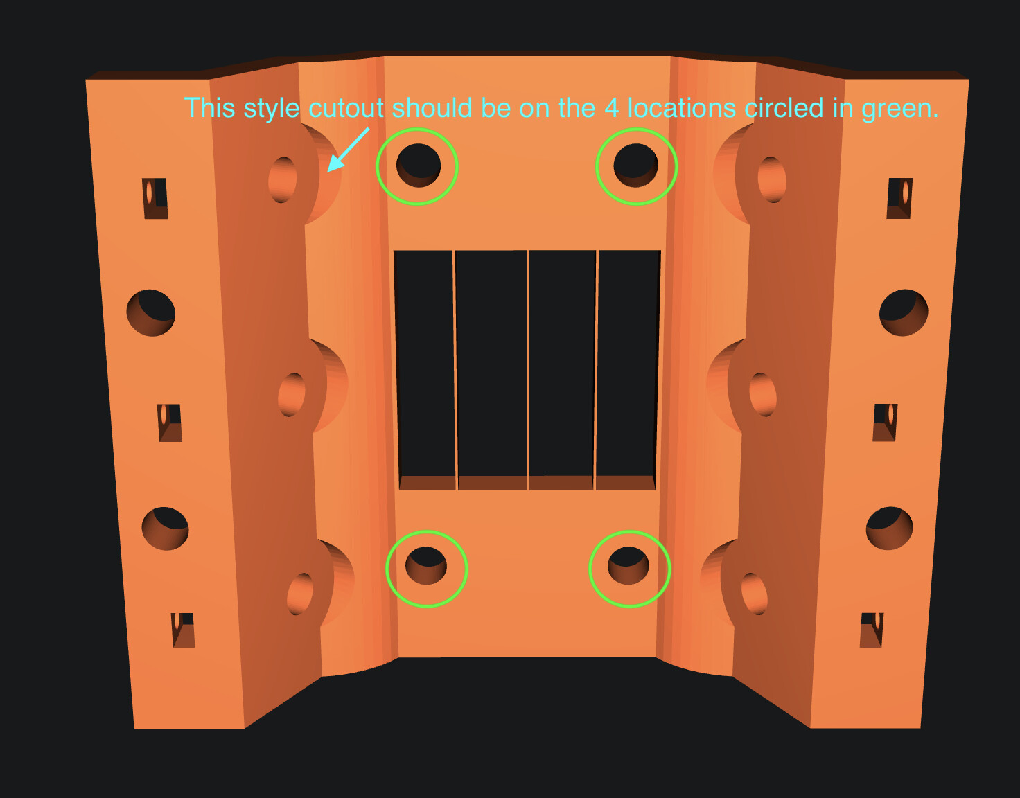
Here’s what I meant about the location for a bolt head clearance cutout. If I remix it I’m going to recess the green areas about 1mm into the part
1 Like
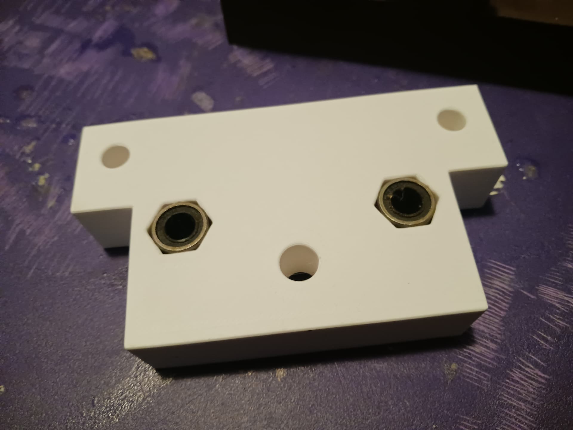
No, they’re hex nuts. The dimensions of the slots for embedded nuts fit the flat-to-flat dimension… to keep them from rotating while tightening.
The guide rods are NOT bolts now… they are real 8mm polished rod, salvaged with LM8UU bearings from discarded printer,
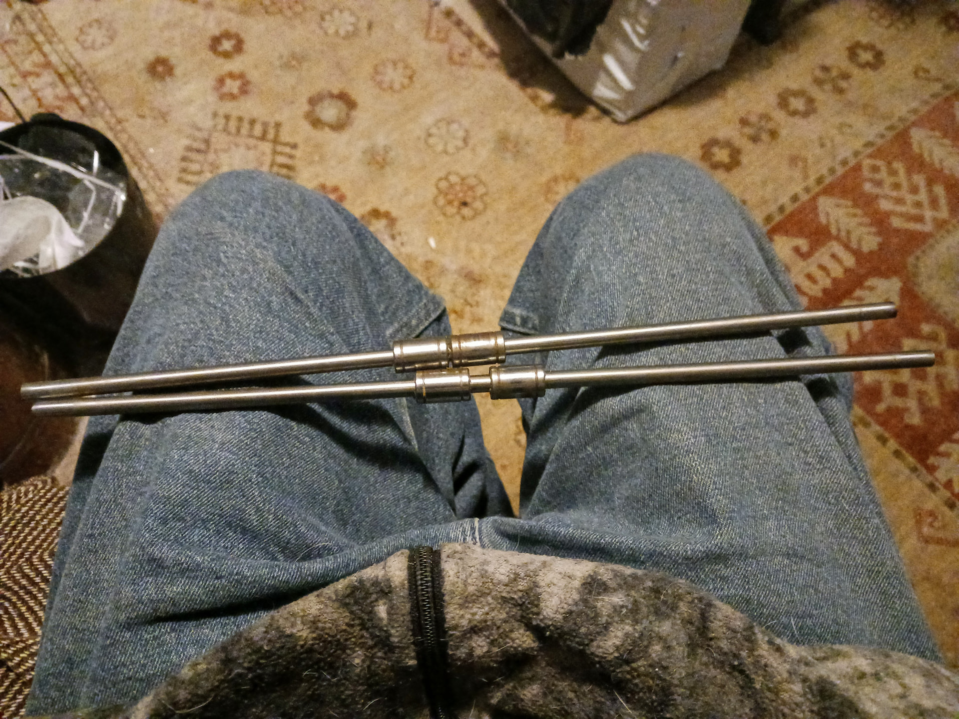
cut to length, and sit in the closed recess in the bottom capture plate and the top end flush with the chassis cap plate.
The original BOLT guide rod holes are NOT USED in the bottom capture plate and the ones in the chassis cap plate and motor spacer are used to bolt together, with a shorter 1-1/4" bolt, fished in from below the chassis cap plate and up through the motor block/spacer. This also captures the top end of the guide rods.
There are no bolt heads now to protrude through the capture plate… and it can sit flush on the table during assembly. Once the capture plate, chassis body, and cap plate are screwed together, everything can now be assembled from top-side.
The original motor mount holes are now also empty… the motor is attached to the spacer block now.
I left the unused holes thinking that if one wanted/needed to… they could revert to the super economical lift stage with BOLTS and printed bearings.
Hope that’s more clear?
1 Like
Yes, very much so.
1 Like
Doberman, anyone?
[for the big MPR&P assuming I get it done in time, closed loop external stepper driver control. I now have all the electronics to build it, just have to get off my butt and make it through the next feew weeks of intense work]
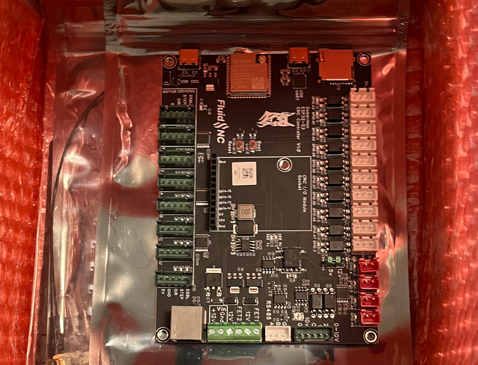
It comes with a medium sized dipole antenna instead of a bow tie.
I also picked up some various Bart expansion modules to compare between the Doberman and the Jackpot V3.
5 Likes
I’ll be interested to hear of your wifi experience after adding an Airedale expander to it.
My 6x CNC Controller’s wifi stopped working reliably (in STA and AP modes; essentially unusable) after adding an Airedale to it. I suspect it’s too much load on the 5V rail, but never got around to testing with an external 5V supply.