I would think a little lube goes a long way. As long as the layer lines never match up, and are able to “catch” each other, friction should be manageable I would assume. I think you already mentioned printing at different layer heights for this reason.
2 Likes
And you think something I may have written years ago – and while possibly “under the influence” – makes any sense? I can’t remember what I had for breakfast…
You still haven’t told me what “lube” would be appropriate.
3 Likes
shoot any lube will work short term. longer term i think the super lube we use is pretty print friendly, but I can verify tomorrow
2 Likes
I’ve been using a “white lithium grease” – sound “appropriate”? Nite-nite…
4 Likes
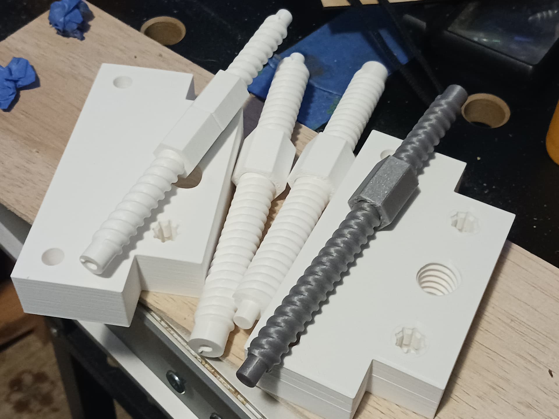
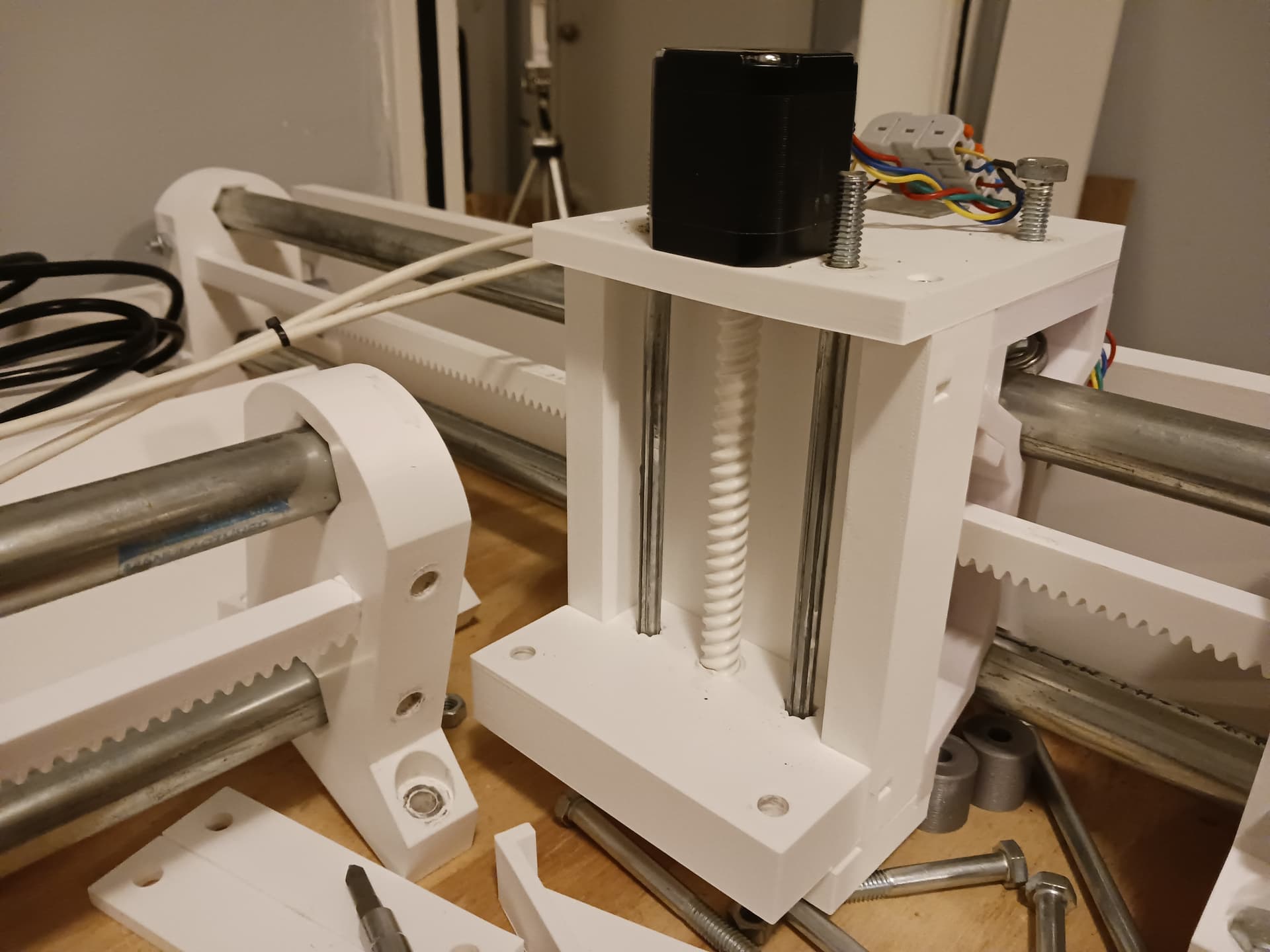
Went into Onshape and increased the minor diameter of the leadscrews to 14mm… and created new lift blocks to match. New 14mm screws and 10mm for comparison…
Disassembling the left lift assembly…
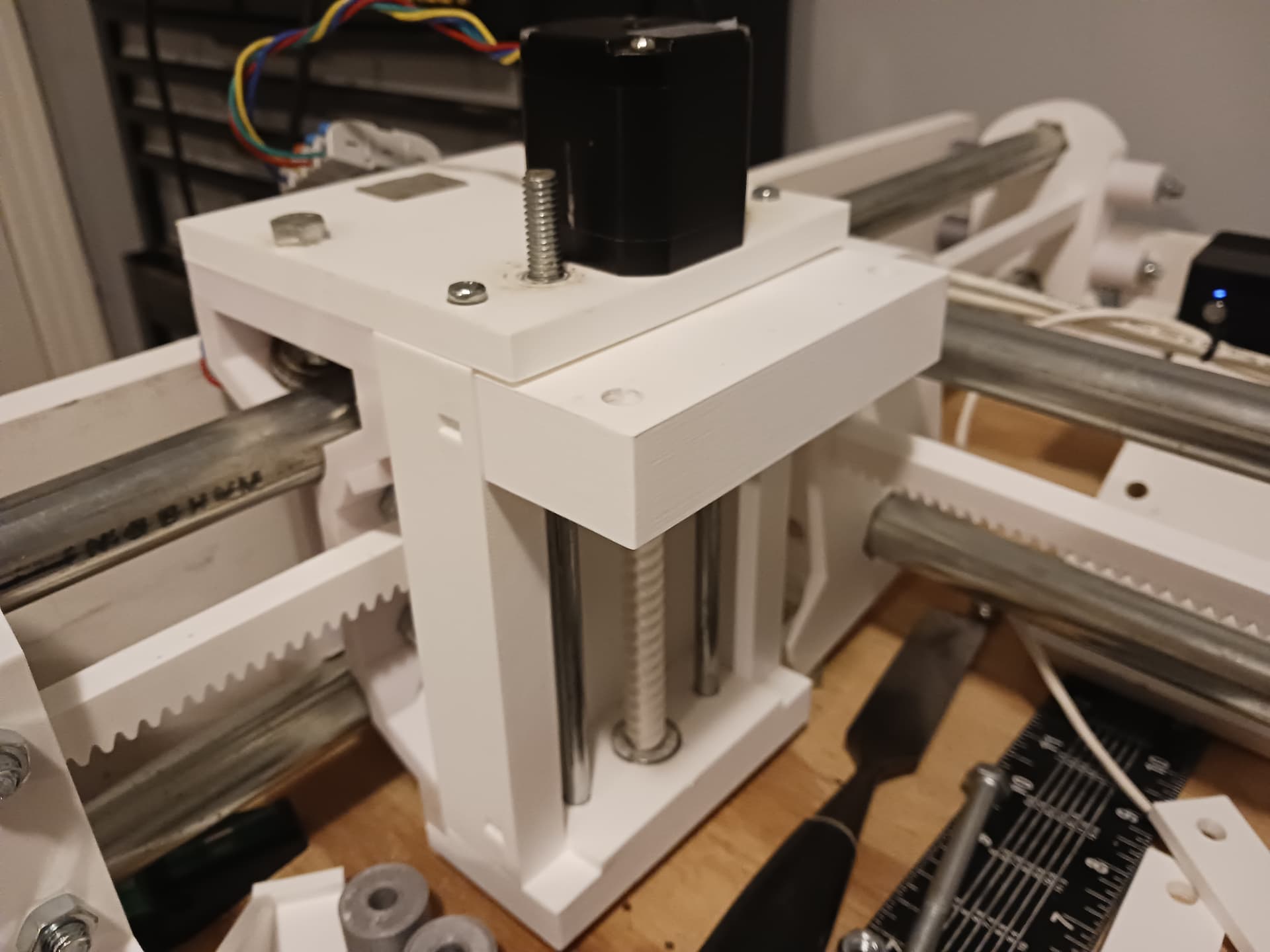
and new one installed. Tighten the guide rod bolts carefully while manually rotating the screw to find where it still rotates freely without binding or excessive slop… and put jam nuts to lock them into position.
One to go…
Later.
6 Likes
I’ll get ready to reprint. Have you given a good test run on the updated parts?
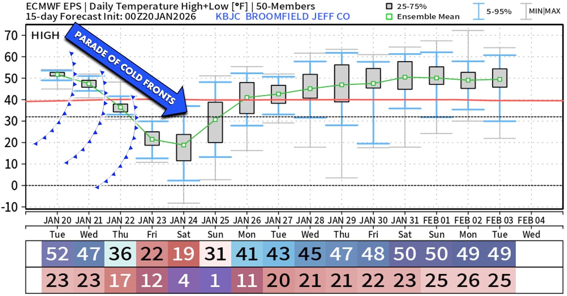
I didn’t spend much time in my unheated garage the last couple of days. It isn’t terribly cold, 12F this morning when I looked at the back deck thermometer; but a bit colder than I like to work on stuff in the garage (was probably about 35 or 40F in the garage).
I may not make much progress the rest of this week on MPR&P as we have a “Parade of cold fronts.”
Will probaly switch back to my Repeat V5 extruder builds and toolheads for the legacy TAZ as I can do that work in my home lab inside the house.
I’m not altogether sure I’m gonna go with the 14mm leadscrews anyway. I’ve seen some weird binding at times especially on one side that leads to lost steps. I know that Ryan said “go huge” but I had far less trouble and far better performance with the 10mm screws… until one broke. I don’t know whether it was just “mistreated” or it really wasn’t up to the task. But I’m pretty sure driving a thinner screw compared to a thicker screw requires less torque out of the motor… and the printed leadscrew is definitely a higher rotational friction “beast” relative to a metal leadscrew to begin with anyway.
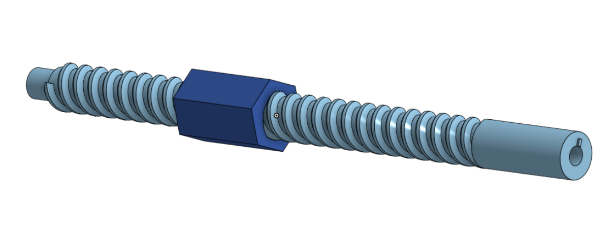
So I’m currently playing in CAD to see if I can stick with the smaller 10mm minor diameter of the thread vs “going huge” and simply finding a way to beef up the motor shaft recess area. Simplest would be simply to increase the overall length of the leadscrew, take the D-shaft recess out of the threaded area into a beefier, larger diameter extended area, and then raise the motor on standoffs or a custom spacer. Something maybe similar to this…
Sorry to hear that you really can’t give it your all yet because of the cold… but hoping you can get to it when you can. I know you’ve said you’d like to take a smallish LR4 or MPR&P to a couple of reprap gatherings. Would really love to see it.
2 Likes
Tomarrow night -14 here I hope they are wrong again or I will need to find my socks.
Yep, I’d have my socks on for that. Maybe even long underwear ![]()
2 Likes
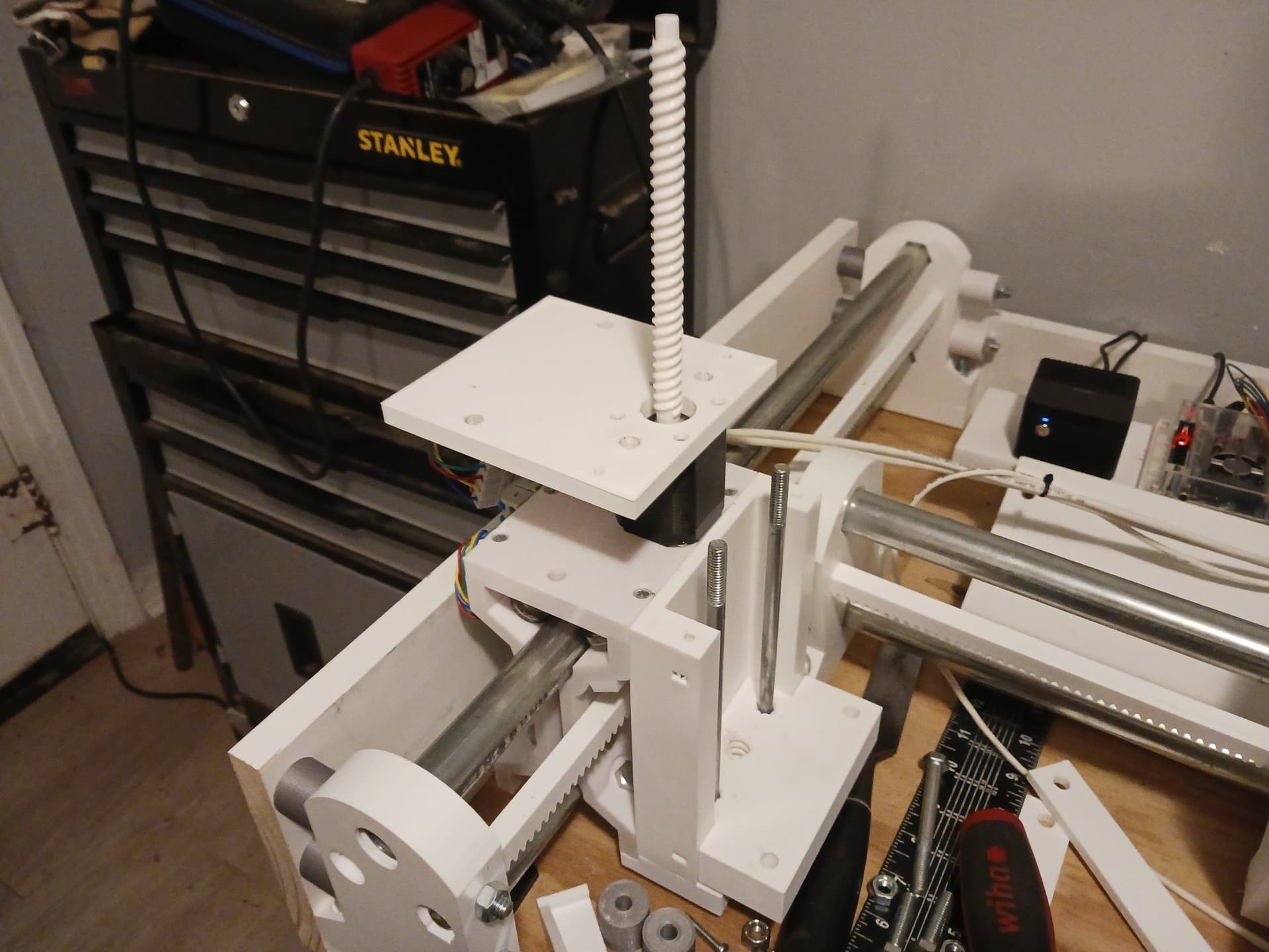
Printing now… a 10mm screw with 14mm diameter extended section enclosing the motor’s D-shaft recess. Also changed the pitch from 10mm to 8mm to mimic LR4… per Ryan’s request.
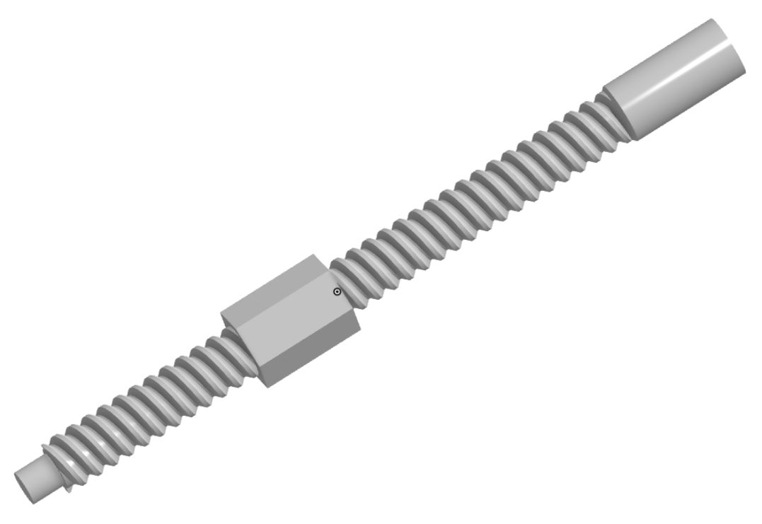
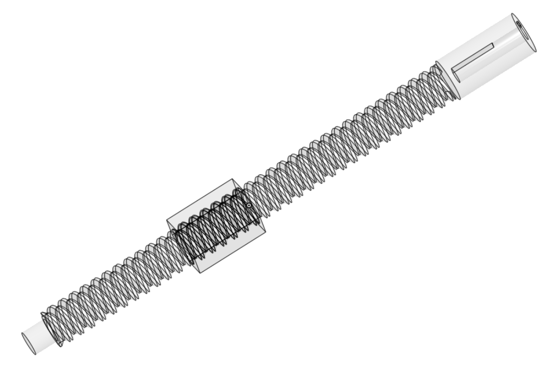
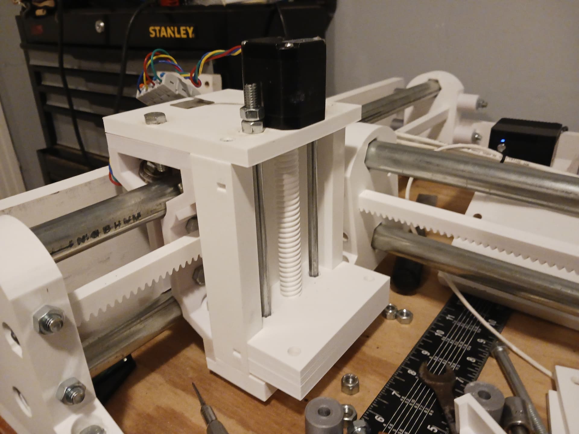
The longer leadscrew necessitates raising the motor by 18mm or so. But there is an added advantage that the new riser block – with motor permanently attached – is held in place with the guide rod bolts… and the motor and riser – and [broken] leadscrew – can be removed, repaired, and replaced as a unit from top-side. With no change in screw pitch or diameter, the lift-block can stay in place, trapped by the guide rods, and be reused with the new leadscrew.
So, hopefully this will be the last time I totally dismantle to upper portion of the Z-lift assemblies. Any future leadscrew repairs should require only the guide rod nuts be removed and the riser/motor/leadscrew assembly lifted out as a unit.
I’ll print the new parts – leadscrew, lift blocks, and riser blocks – and install and test before I update Printables. If anyone (Jim?) wants to give this a try before I update Printables, let me know and I can drop them here in a .zip file.
Later.
3 Likes
Looks good!
If this doesn’t fix it, it occurs to me that when you zero by running into the top plate you have both a torsional force and a perpendicular force trying to pull the screw’s layers apart.
You could avoid (well, reverse) the perpendicular force by zeroing in the opposite direction. You could place blocks between the bottom and travelling plates (for zeroing only) to facilitate that (assuming that you can’t run the travelling plate all the way down to the bottom plate with a tool attached).
I guess this would necessitate no up/down play in the screw, motor, etc. connections, though.
2 Likes
I think you may be right about the top-plate “impact driver” action… trying to separate the layers. The bottom plate would be better and I do have uniform spacers that rest on the bottom plate to de-skew with a tool in place. Thanks!
2 Likes
I’ll test with the updated files. Send them over when you’re feeling good about them.
1 Like
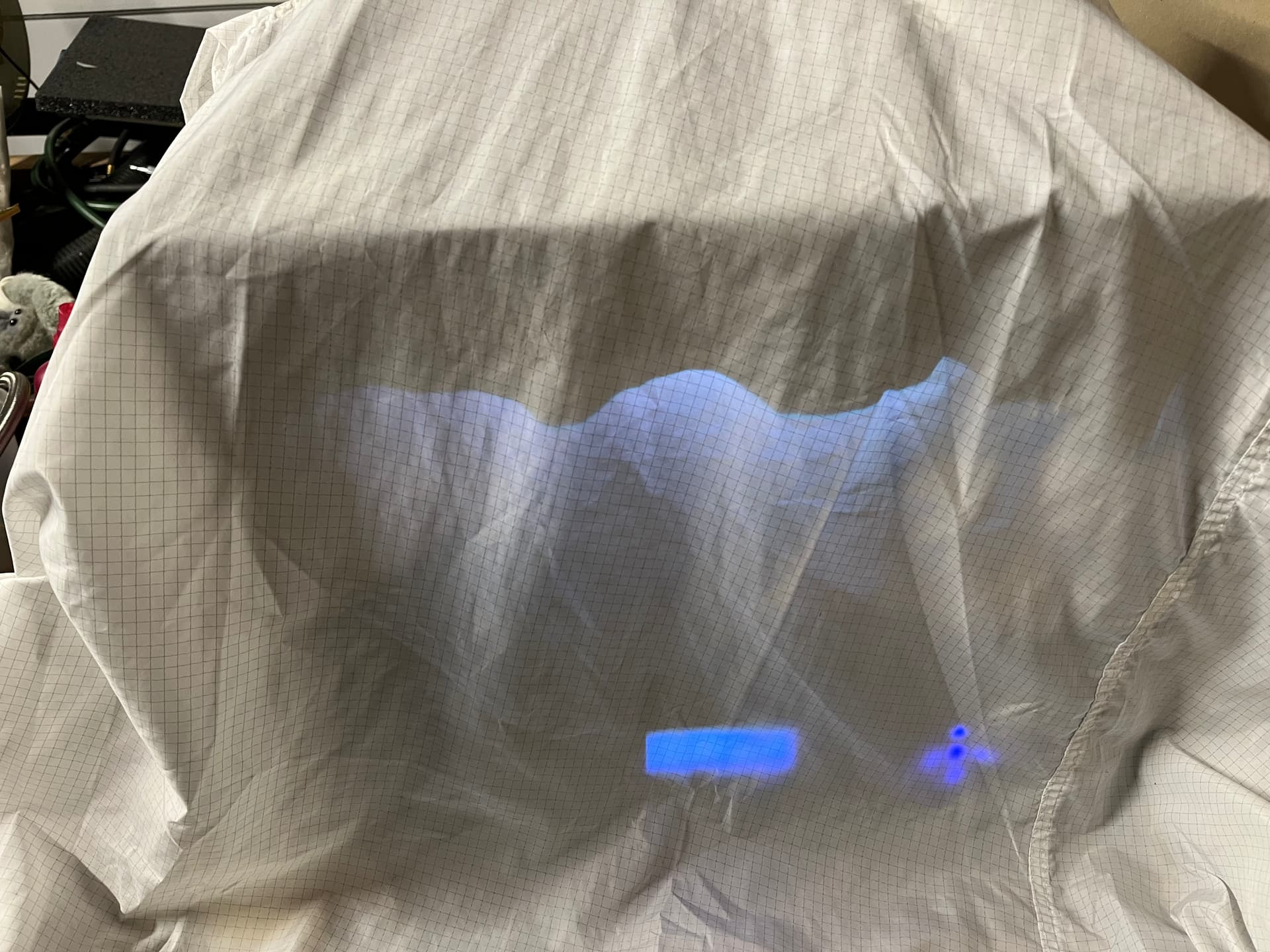
That time it was 1F outside and 35F in the garage.
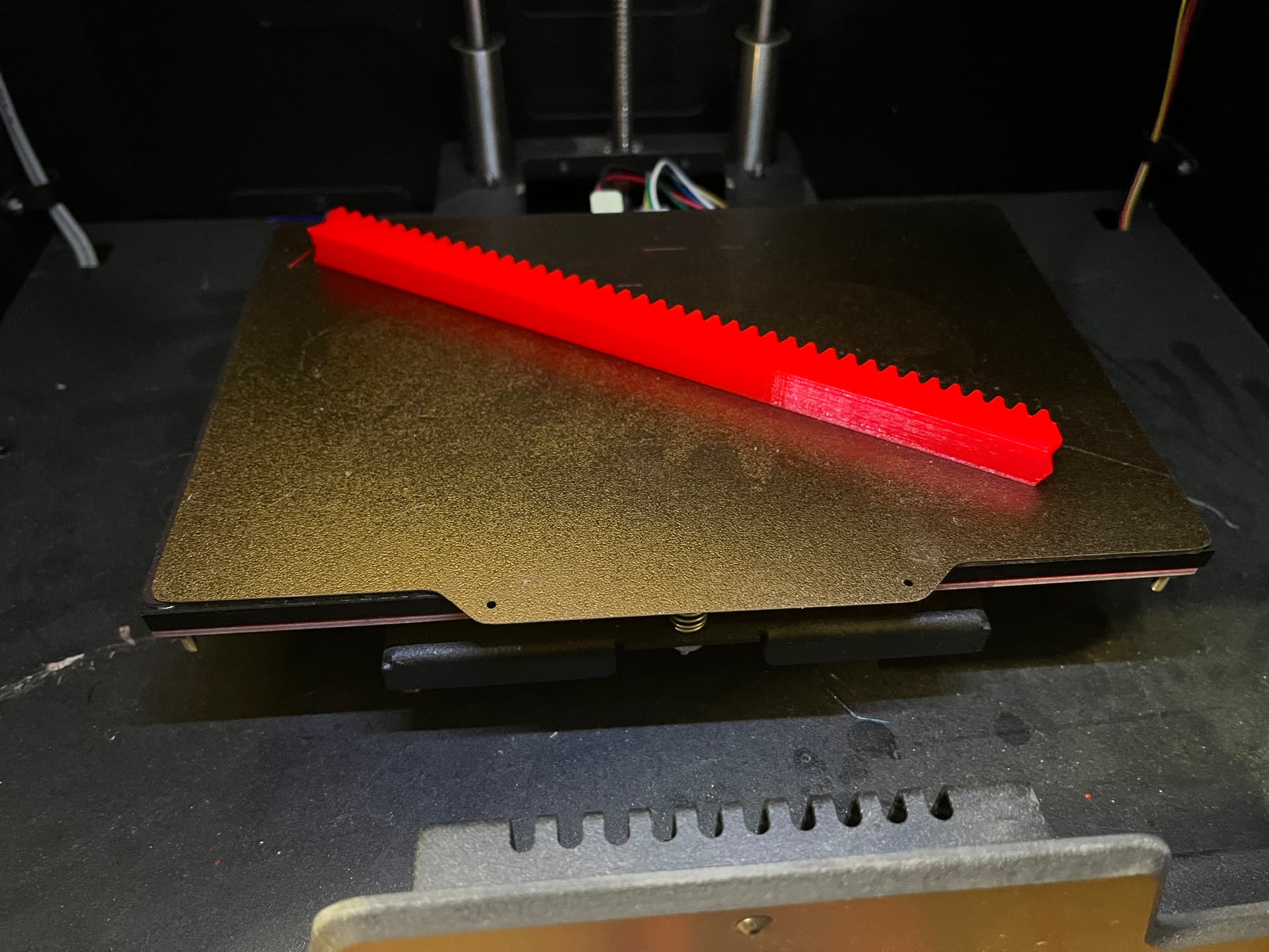
So I put an old tyvek clean room jacket on the printer and fired off a 40 tooth rack print.
The Core One L is busy with grandkid job at the moment. The Taz are mostly getting disassembled to become repeat printers.
Maybe if it stays above 32F I’ll spend some more time in the MPR&P rebuild.
2 Likes
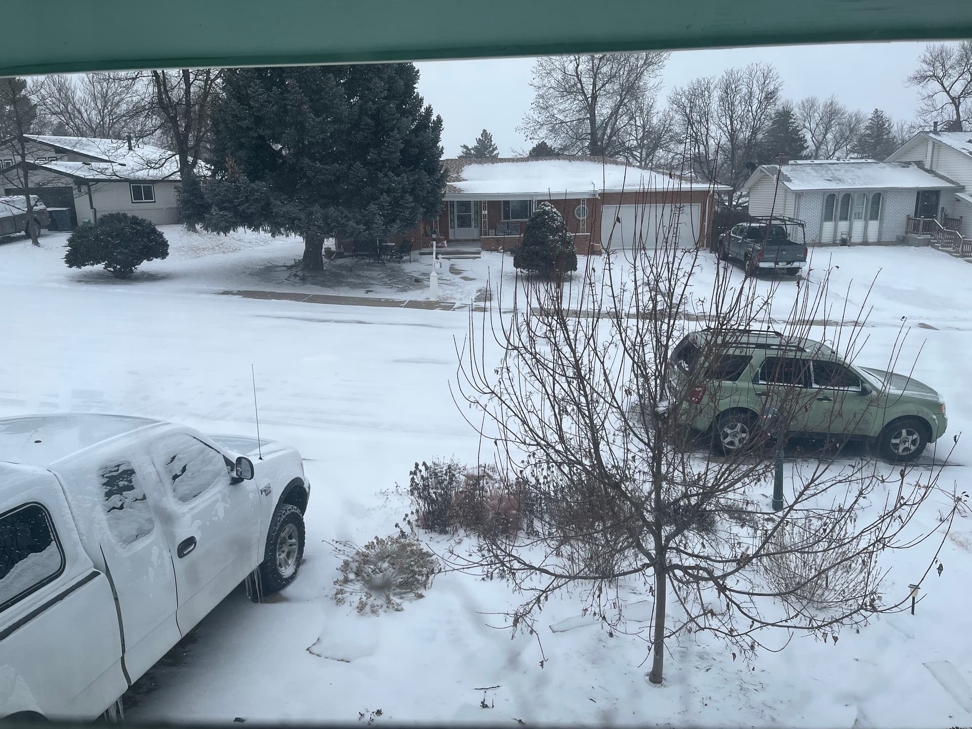
Watching the Patriots/Broncos game being played in Denver… started in bright sunlight and clear field… snow started about halftime, blizzard conditions, field completely white at start of 4th quarter, can’t see the yard lines even though they’re trying to clear them. Silly Patriots decided to wear their all-white uniforms… ![]()
EDIT: Patriots white uniforms might have actually helped. Denver QB couldn’t see the defenders clearly… ![]()
I’m printing test parts while watching…
3 Likes
2 Likes
Have to go to the high hills for the big snow.
It’s been since the late 1990s that I had to dig out snow more than a meter deep down on the front range, and typically not over 10 cm down here.
There are no lakes here, so no lake effect snow.
4 Likes
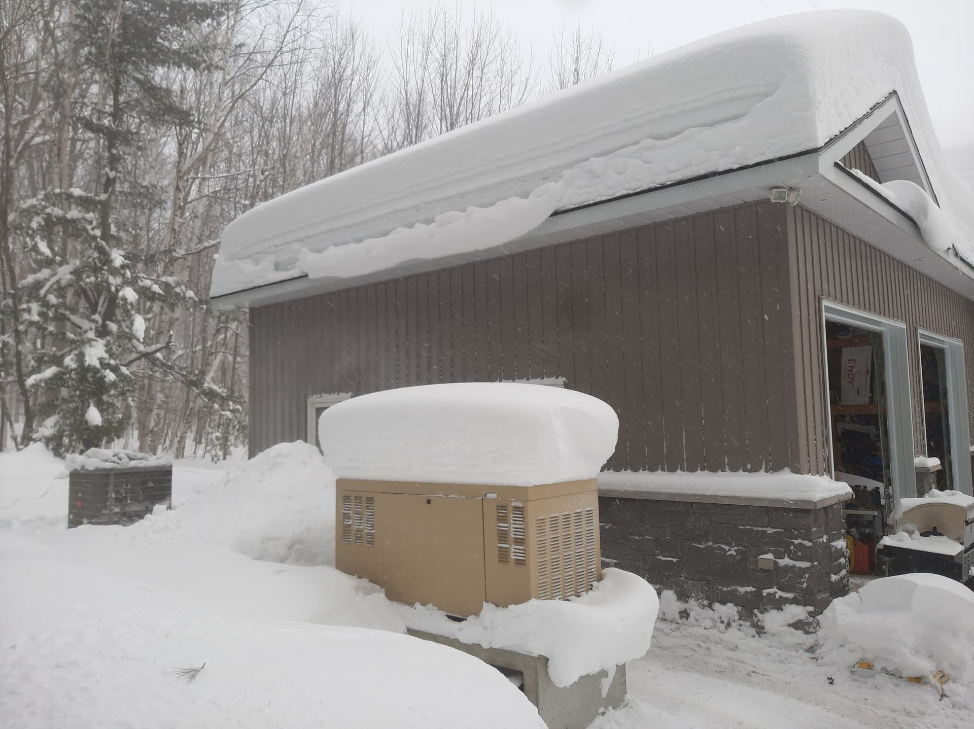
Spent more time working away.
Cleared off most of the last of the MPR&P V1 from the old table. There’s an early LR4 beam build with fully printed strut plates. Surprisingly stout.
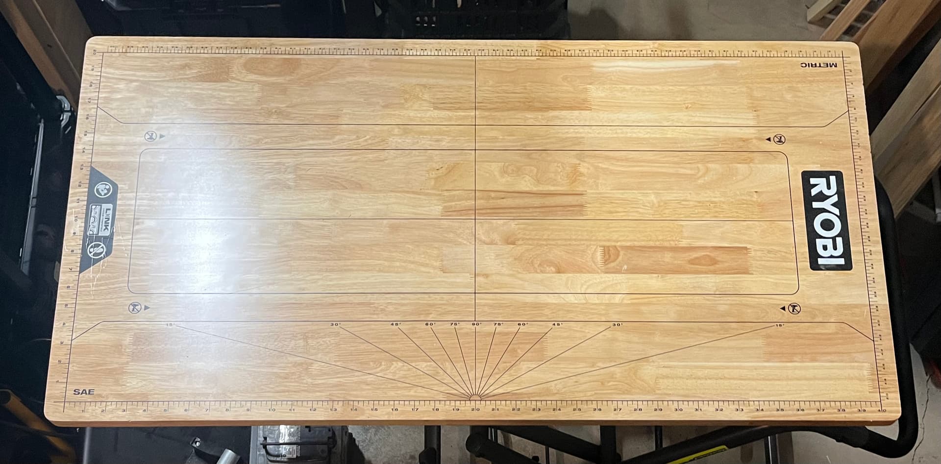
Here’s what the top of that infernal Ryobi bench looks like. I’m tempted to remove that surface, but then my plan for potentially making a larger MPR&P for RMRRF gets more work, so I’ll likely leave it.
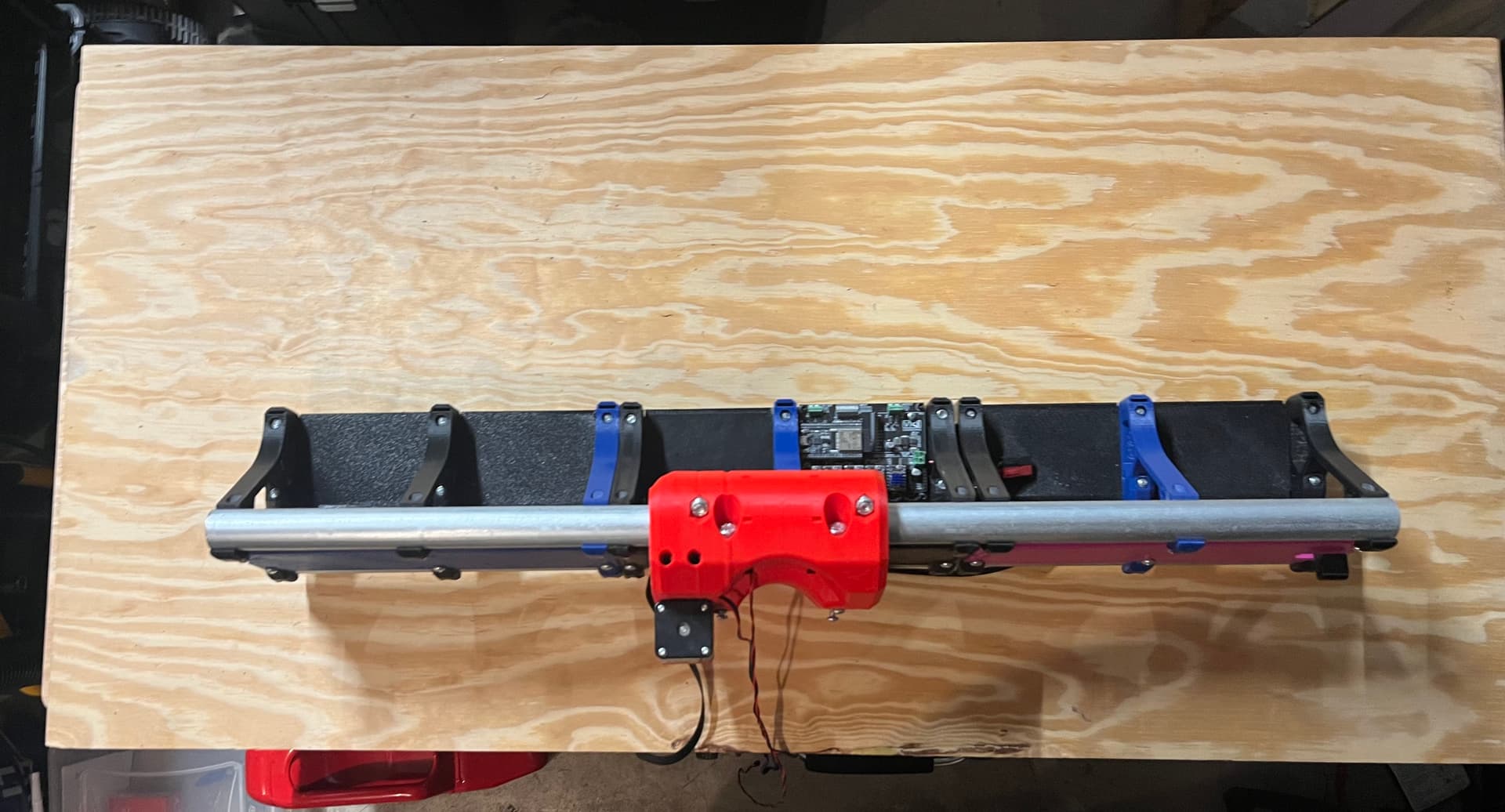
Back on with the slightly thicker 3/4" by 2’x4’ project panel, mocking up the new stubby Y axis.
That is two 40 tooth segments and one 20 tooth segment. So, 100 teeth of rack.
I have extras, for the larger build I may attempt.
I had been using fender washers and coupler nuts on the MPR&P V1 build, these look to expect just standard washers. I’ll come back to that.
Since the EMT is captured by the ends, I’ll need to measure and cut those, which I’ll do some other day. My feet got cold, and that’s when I stop ![]()
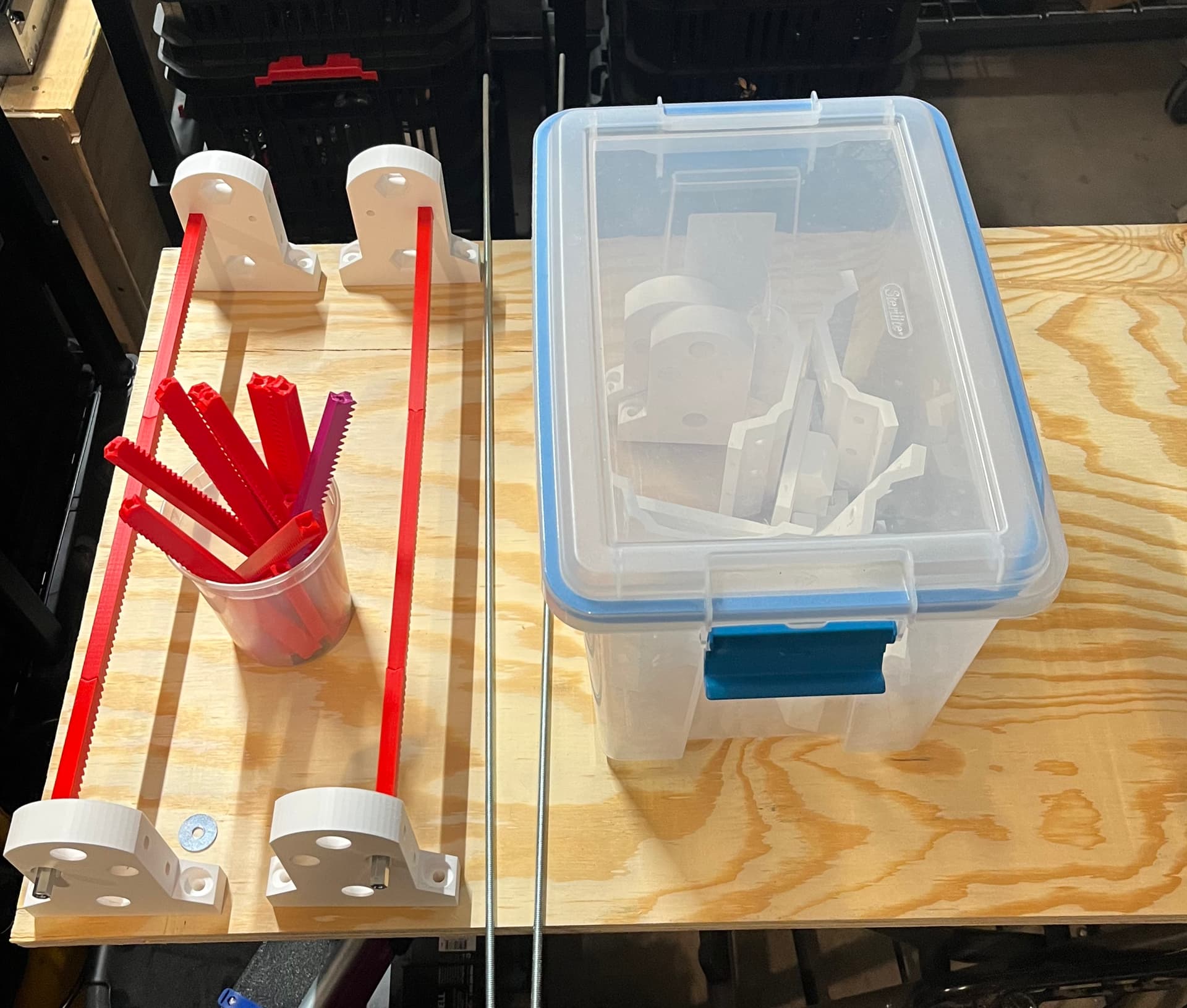
The printed-in-the cold rack segment turned out fine:
I fired off another one which is almost done.
Now, where did I put the longer 1/4" threaded rod???
4 Likes
An update…
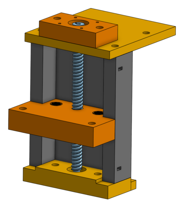
While I’ve been fiddle-farting around with the design of these printed leadscrews, I decided I need to show that a QUITE MOST PROBABLY BETTER lift assembly could be had using the LR4’s T8 leadscrews (and linear guides)… if you happen to have them and/or want to help support Ryan by buying new ones.
This modified T8 leadscrew driven lift assembly is quite similar to the printed screw lift assemblies I’ve been playing with but a couple of minor changes are required. I enclosed the bottom plate and added a BB-“bearing” surface for the bottom-end of the leadscrew to rest on.
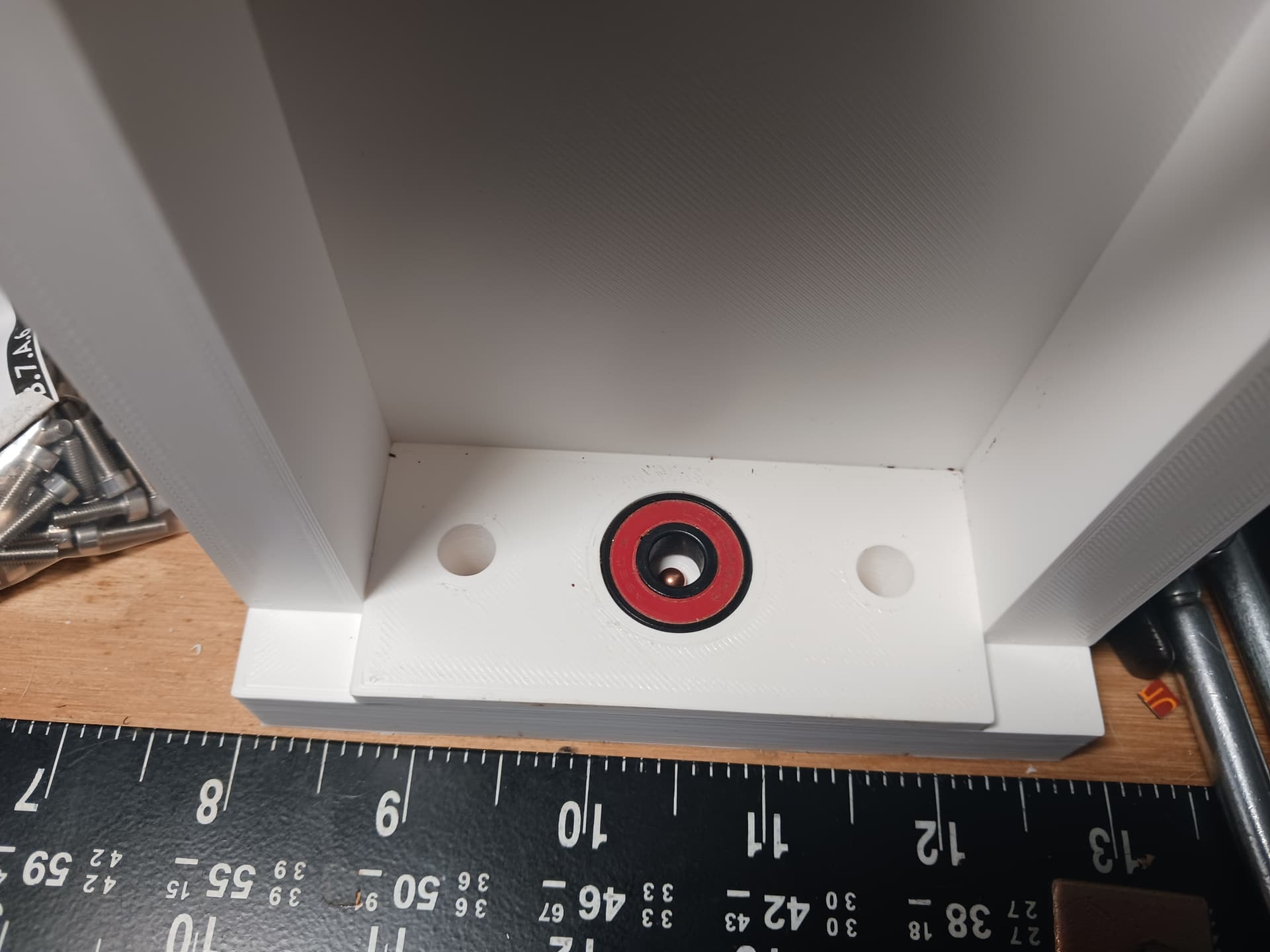
And, for now, I’ve stayed with the guide rods…
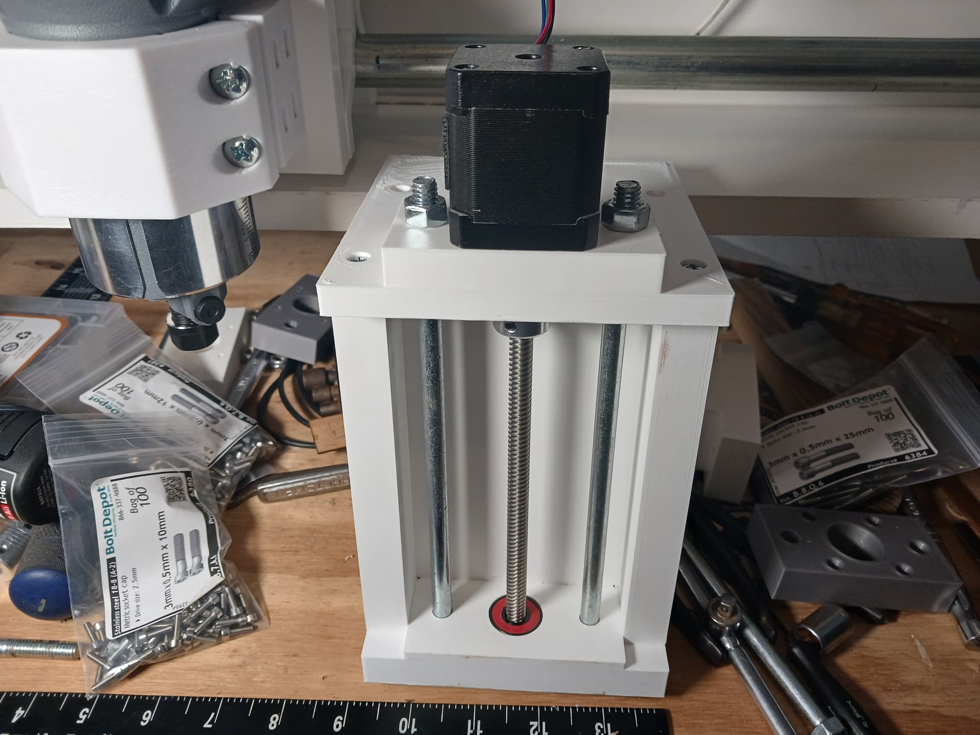
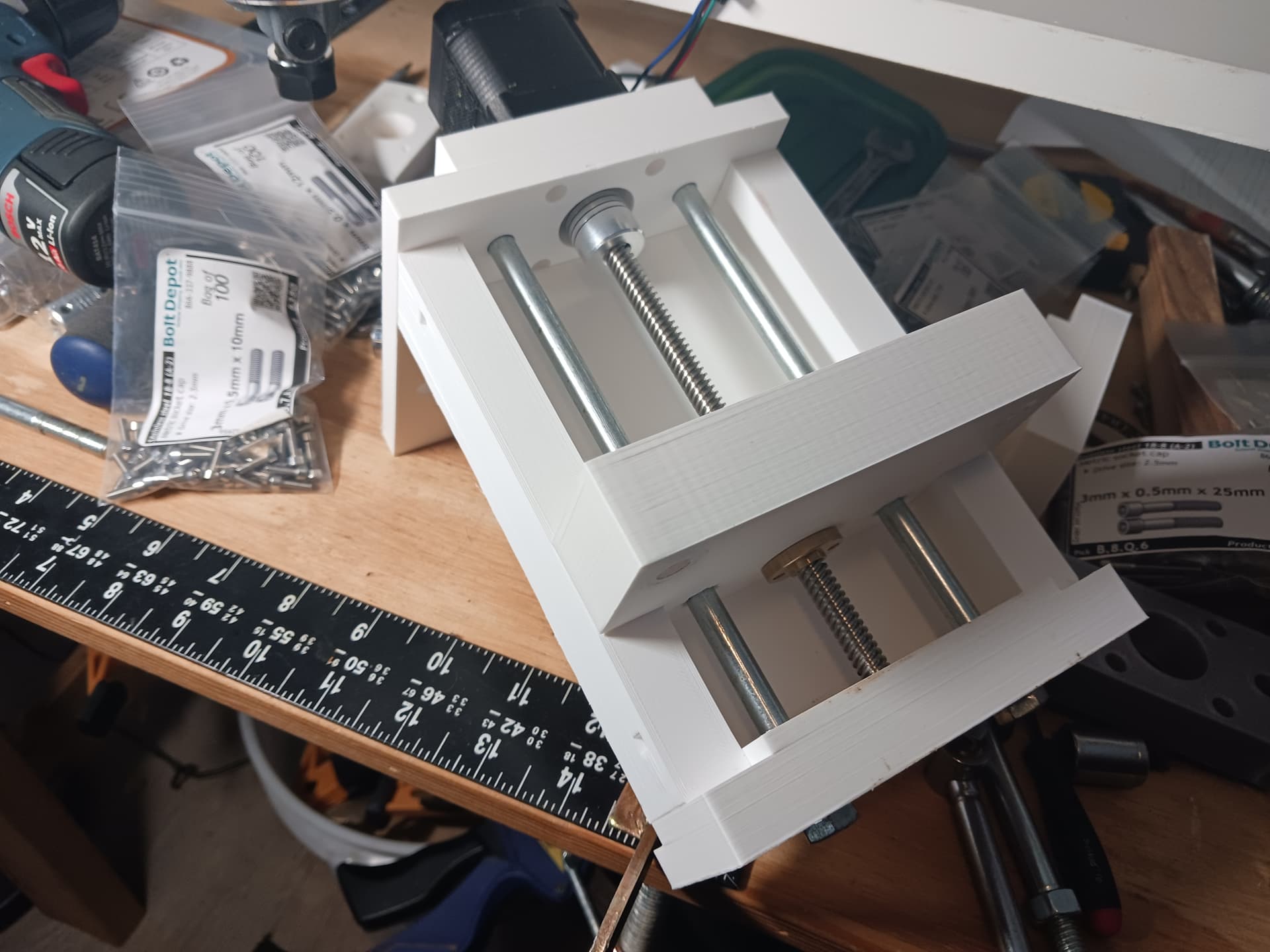
Here it is in action. It’s really noisy with no lube of any kind for now but I want to do a bit more testing if I should decide to get serious about using it.
and I’ve already demo-ed a linear guides version before…
Best, of course, would be to use both the LR4’s leadscrews AND linear guides… but that would move it out of the realm of a “junkbox build” for most and add a bit to the cost of the build.
So, with that being my “plan B”, I’m now gonna continue playing with the printed screws and guide rods until I’m either happy with them… or get tired of messing with them. I really want the printed versions to work more reliably before recommending them as the MPR&P’s “yellow brick road”… but I also felt it necessary to show that there is an less-risk path forward for MPR&P, even if I can’t get the printed screws to work as well as I’d like.
Another thing I want to do is go back and redo some pen and laser testing now. I’ve been air-milling some pretty lengthy multi-hour jobs, such as the Aztec calendar @joegomez1479 did… and it has served as a real “torture test” for MPR&P. There are so many small XY movements and Z lifts that MPR&P gets really noisy and sounds a bit “crunchy” at times… so I want to repeat some testing to insure nothing has rattled loose.
Later.
6 Likes