David, well, it looks like you’re ready for some files to test it out. I will have them sent over today for you to try. I’m really impressed with that machine; it’s super cool!
1 Like
I’ve continued printing parts, and ocasionally making random robot noises ![]()
I printed a 65mm tool mount, and remembered that it has a cutout for a laser module as well. I’m off scrounging to see if I have one in that form factor.
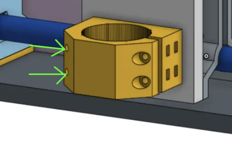
I do have a question- on the right side (clamp side), there are a pair of nut traps for attaching to the tool plate from behind, and another pair for retaining the nuts for the tightening screws.
On the left side, there’s a pair of nut traps again at the rear and then the screw holes go all the way through the part (see below).
Is there a reason the screw holes go all the way through the part?
I’m considering adding heat set inserts in the meaty part where those screw holes emerge, and can’t figure out a reason those holes are full through holes…
I mentioned above that I’ve got mixed feelings about my Ryobi Speed Bench mobile workstation.
It’s a TERRIBLE dolly when folded up because it’s terribly heavy and the table top occupies half of the bottom foot of the dolly. Dumb.
When in table mode, there aren’t handles to grab and roll the thing around on its wheels without having to stoop. DUMB.
It’s table surface is 22" by 42". Not terrible, but not great either.
Now, look at this fellow (From the Ryobi product page at their web page.)
Does he look like he’s having any fun?
I can tell you as an owner, no he’s not. He’s cursing that damned thing.
(And, as an Aside, what a dumb way to move that saw!!)

When I was staring at it and debating how to configure it, I realized that I could put one 2’x4’ project panel of 3/4" plywood on it and it would make an OK small form factor machine. Then I realized that if I were to turn three of those same 2’x4’ panels sideways, I could configure a 6’ x 4’ work surface (would need to add some meat around the outside edges.
Those three panels would be easy to remove and would make for a setup that’s super portable.
The upside of that is you end up with a machine that can cut a full 2’ x 4’ project panel, and for many users of this type of machine that seems a practical maximum and also very much an achievable footprint.
So, I’m going to start by building up a small machine in the 2’x4’ size, knowing that will be easy to take to RMRRF with the portable table.
I’m also going to continue printing parts and maybe (just… maybe) I’ll set up the 6’ x 4’ size as well.
The 2’x4’ will get the jackpot and ordinary V1 steppers. The 6’x4’ machine will get closed loop steppers and some kind of controller that support external stepper drivers.
So, I’m back to printing parts and fiddling plans for the machine build(s).
2 Likes
Actually, no. And my printed part doesn’t have them… I stole this one from the original MPR&P.

I guess I accidentally captured an early CAD version when i was adding the nut traps. I’ll update Printables. Meanwhile here’s the proper version, I think…
65mm_router_mount.3mf.zip (51.6 KB)
I like it. My MPR&P-V2 has an almost exact 2’ x 4’ footprint and sits on one of those panels.
My only question would be… are those 2’ x 4’ project panel always guaranteed to be square? I’ve always assumed they were cut in-store with a panel saw in unknown condition and possibly operated by folks with limited experience? Or, do those 2’ x 4’ panels actually come from the factory… with factory edges?
I’ve been doing a fair bit of air-milling and have noticed that sometimes one or the other Z-lift loses a few steps and the gantry beam will be slightly off “level” from where it started. It doesn’t always do it for relatively short runs but it’s usually off on a 40 minute vcarve job. I’m thinking of upping the Vref a touch to give the Z motors a bit more current… but also thinking maybe I need to slow the plunge rates and possibly lower the acceleration on that axis. Thoughts? What are the typical plunge rates and accelerations on LR4? I’ve only guessed for MPR&P to this point.
Anxious to hear more progress reports on your build. And thanks for catching the router mount snafu.
Later.
1 Like
The settings I have for my Jackpot are: plunge = 500mm/m and acceleration_mm_per_sec2: 80.000
1 Like
Factory, factory edges. Are they square? Good question; I’ll measure the ones I got today.
Yes I think those are all good steps to take.
The larger machine is going to get closed loop stepper drivers.
Not a snafu. I spent a bunch of time trying to figure out what those holes were for ![]()
Which led me to some other ideas.
All good.
I’m going to copy your small table layout, the long X is better for laser.
1 Like
Thanks, Britt. I now see the LowRider’s config.yaml out on Github has Z max rate and acceleration of 1200 and 80. I had 2000 and 60 so not too different. On my last 40 minute air-mill, it may have skewed a step or two but not too much… judging from a bubble level I have on the tool carriage. The job itself specified plunge rates of 30 inches/min… er, 762 mm/min… ( @joegomez1479 gave me the file and he still works in inches…) so it doesn’t seem unreasonable. I did go ahead and change my Grbl settings to match the LR4’s 1200 and 80 settings however, since I’m trying to mimic LR4’s proven Z-lift characteristics.
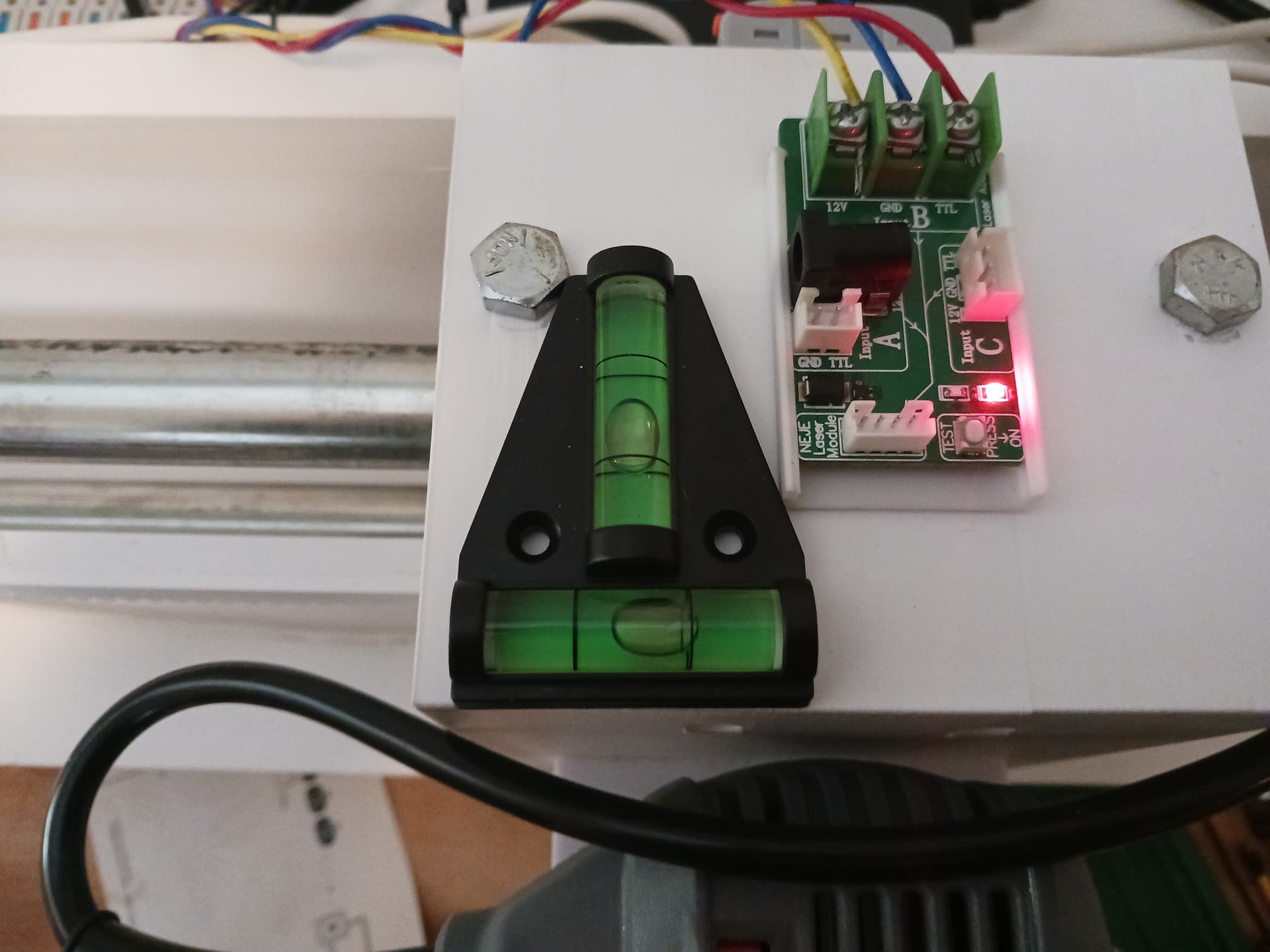
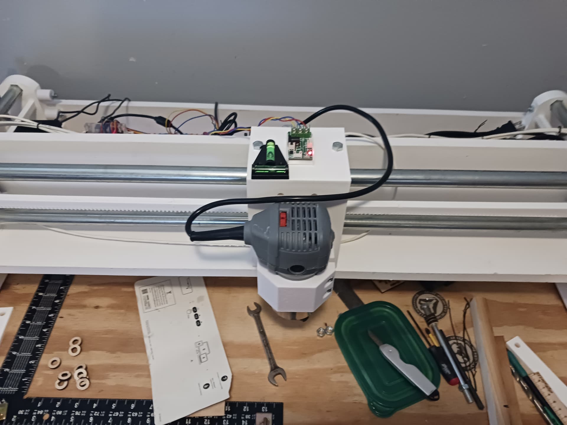
Here is the unique view I have from my recliner while air-milling these vcarve files…
and periodically I hear an odd “grunt” in all the “robot noises” (as @MakerJim calls them). When I got up to go look closer I can see what appears a small skew from “level”… the bottom bubble was near centered at the start of the job. That’s what I’m trying to track down… why?
[An observation: AFAICT the bubble always(?) moves right, which would seem to indicate the LEFT lift assembly might be the one losing the steps and ends up lower than the right lift.] The motors are wired in series. I’m leaning toward upping the Vref to increase the Z motor current a bit. Since it seems okay MOST of the time, with ONLY occasional “grunts”… maybe the motor current is just “marginal”.
Again… thanks, Britt.
4 Likes
David, the Jackpot Z motor current settings are:
    run_amps: 0.900
    homing_amps: 0.900
    hold_amps: 0.80
How different is this from your settings since you are running the Z motors in series?
Britt,
This is just a guess on my part as I’m not real sure what little step-stick drivers are integrated on my little GRBL controller… but I’m guessing they are A4988’s, as this is a board often offered with the small 3018 desktop CNC’s that are so common.
So, assuming A4988’s, I’m going to back out the current on my Z motors. I set the Vref IIRC at about 0.72 - 0.73 VDC. Assuming a commonly used 0.1 ohm sense resistor (it’s under a heatsink and I can’t see it), I calculate the current as Vref / (8*0.1), or 0.73/0.8… the current should be ~0.91 amps. Since both motors are wired in series, they both see the same current… so, 0.91 amps.
I believe it… the motors are just pleasantly warm, even after cooking for hours at a time. In my experience, that seems about perfect. (The little Grbl controller, however… not so much. The heatsink on that baby cooked pretty warm when I had the cover off and was setting Vrefs… but it has a fan on it so it seems to be holding up for now. ![]() )
)
– David
From the All3DP website…
How to Calculate VREF
VREF is calculated with a simple formula:
VREF = I x 8 x Rsense
Where I is the driver current to the motors and Rsense is the current sense resistor. While I is primarily defined by the motor’s rated current, Rsense is a fixed value that can be verified by checking the stepstick board.
Sense resistors vary from vendor to vendor, ranging from 0.05 up to 0.2 Ω. Look for two equal resistors in the A4988, as shown in the image above. In this example, R100 is 100 mΩ, or 0.1 Ω.
Although the stepper motor we’ll use here is rated for 0.9 A, we should never set it to its maximum current capacity. It’s strongly recommended to reduce the amount of current to the motor by at least 10%, which in our case would translate to approximately 0.8 A.
VREF = 0.81 x 8 x 0.1 = 0.64 V
2 Likes
You would be lucky to ever have them available if they were cut in store. Between stocking, loading, customer interaction, and staffing there is no way ![]() Not to mention the saw issues and matinenese
Not to mention the saw issues and matinenese
1 Like
The blue big box store where I got my panels hasn’t had a working panel saw for months.
1 Like
I think I’ve confirmed that the Z motor current needs to be increased just a bit more.
While air-milling a ~420mm X ~280mm carve, I had been setting the job origin (0,0,0) in the front left corner… and losing steps during a 40 minute carve job… and always to the same side. So I moved the job origin 200 mm in X toward the middle of the machine and ran the next four consecutive 40 minute runs without losing a discernible step.
Apparently, the weight of the router, biased toward one end of the gantry during most of the run, was enough to cause an occasional loss of steps at that end. Keeping the weight of the router more in the middle seems to have “cured” the loss of steps problem.
Having just done the currrent calculation for Vref in a previous post… it appears that pushing 0.8 VDC on Vref would set the motor current to ~1 amp.
1 Like
Alternatively, you can lower the accel and get a lot more power out of it.
1 Like
That’s good to know. “A lot more power…” would be nice. I’ve not yet increased the Vref but also really didn’t know the effect of the acceleration on motor torque. I really didn’t want to make the motors and controller run hotter than they are now, if I don’t have to.
However, I just broke another leadscrew… a 10mm one this time. And just about in the same spot…
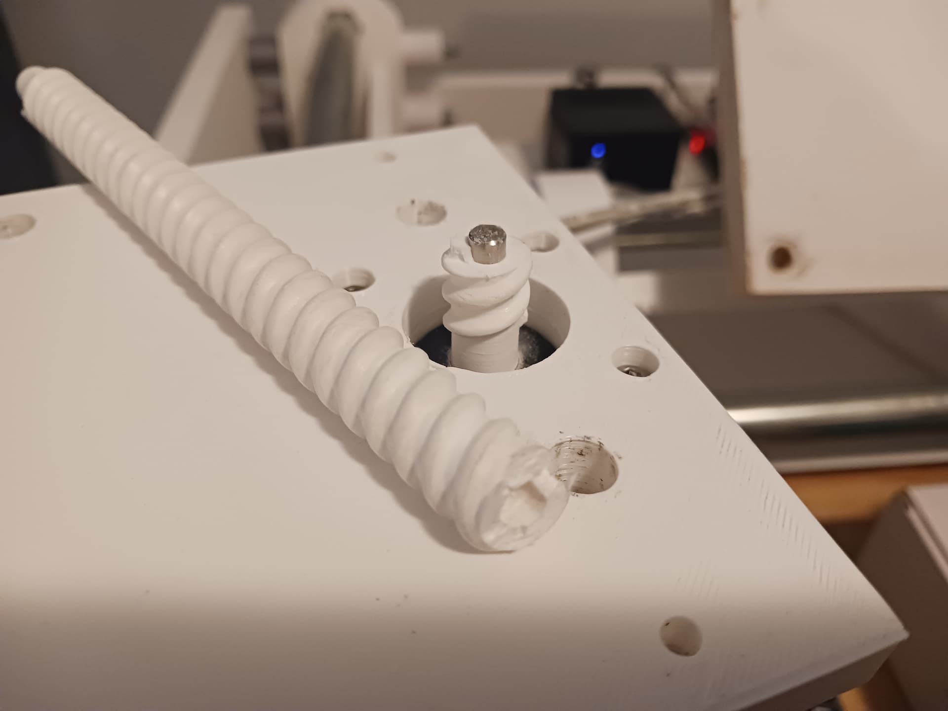
To its credit, it’s been running beautifully for the last day and a half or so… ever since I start running jobs more in the middle of the machine rather than at one end. And I had run that 40-minute badge job at least 6 or 8 times with no discernible loss of steps… until it decided to break while demo-ing it for my SIL.
But it’s also the one that was taking a beating when I was trying to figure out why I was losing steps on that side. And, maybe I’m just underestimating the torque of those little motors when I was running them against the hard stops to square it all back up. I suspect it may be the “impact driver”/hammer-effect of running briefly against the hard stops that’s killing the leadscrews.
I’ve got a couple of extra leadscrews printed up so will probably just go ahead and replace it. Now that I know why the gantry was losing steps on one end, I should be able to not torture a replacement screw quite so badly while I continue testing and playing with the machine.
I really don’t want to go to metal leadscrews and a coupler… though it could be done easily enough by raising the Z-motors up on standoffs to make room for the coupler. I bought a set of LR4 leadscrews initially thinking I would probably use them and the linear guides. I’m sure that would actually be the best, though more costly, setup anyway.
But I’m still not ready to give up on the printed parts. I might increase the diameter of the printed screws one more time… to put even more meat at the spot these others have broken. I could make them much larger in diameter, of course… but just don’t know the effect on the motors of the increase in friction; i.e. they may be a lot stronger than I’m giving them credit for, judging from the broken leadscrews I’ve had.
But hopefully I’m learning enough to stop torture-testing the machine so badly… and maybe the printed parts will prove to be good enough under normal use.
2 Likes
Go huge, no reason to make them small.
The issue I ran into is speed tuning. We used to use threaded rod, but the max speed was horrible. So we switch to the T8’s. I would say for now stick to an 8mm pitch so you can compare to the specs we have been using for a long time..
The slower you accelerate the more chance you have of getting to the peak torque of the stepper before you ask it to move too fast.
https://www.omc-stepperonline.com/download/17HS08-1004S_Torque_Curve.pdf, kinda gives you an idea that you need to get out of the no torque zone…then you get all your torque really quickly.
2 Likes
Do you really need threads in the leadscrew around the motor shaft? If you deleted the threads and had the full diameter of the leadscrew for about 1/2 a diameter or more above (well, below since it’s inverted) the internal shaft void it’d be a lot stronger.
2 Likes
Just so I know for sure… my 2-start printed screw moves 10mm in one revolution; i.e. each of the 2 helix are 145mm long (the length of the actual threads) with 14.5 turns. I’ve assumed that is a pitch of 10mm. If so, then for the same 145mm thread lenth, I could get a pitch of 8mm with 18.125 turns. Am I computing the pitch properly?
Does the T8 threaded rod move the nut 8mm per revolution?
1 Like
Yes and yes.
I bet just playing with the accelerations you will make what you have work, once you beef them up a bit more.
2 Likes
My reasoning was that I wanted the top plate to which the motor is mounted… to be a hard stop for correcting for any possible skew between the lift assemblies due to lost steps at either end. Same at the bottom end of the leadscrew. Also having the threads themselves not terminate in the full diameter of the screw allows the leadscrew to be replaced from either above or below.
However, since Ryan has blessed a diameter increase even more significant than I might have “snuck up on it” (I was concerned about the friction increase with longer thread area spiraling around the shaft… ), I should be able to put “more beef” in that area without really changing the design goals I had for it. I started with a minor diameter of 8mm, then went to 10mm and the motor shaft is of course 5mm. Going to 12mm or 14mm would be easy enough and give significantly more “beef” than in the screws that “almost worked” anyway.
By “huge”, Ryan… is a 12mm or 14mm “minor diameter” on the leadscrew (it’s 10mm now…) huge enough? Any thoughts/worries about “thread friction” with same thread profile but longer circumferential length? Are these little NEMA17 motors, properly operating in their curve, more 'torquey" than I’ve been giving them credit for?
Later.
2 Likes
You could also try printing slower (in that section) to increase layer adhesion so that it might better resist the torsional forces.
You could also run down the rabbit hole of sensorless homing.
2 Likes
Thank you, Daryl.
I’m a near-80 year old “hack”/retired EE and getting into 3D printing any deeper than I already am… no thanks. I’ve got enough on my plate already.
While sensorless homing would be sweet, I pulled an 8-bit GRBL controller with A4988/DRV8825 drivers out of my “junkbox”/stash and I actually get a kick out of making old stuff “go”. Both the MPR&P and MPR&P-V2 have been, from the start, “junkbox builds” for me… except for filament.
I expect – should anyone actually build one of these things – that modern controllers and limit switches will be a requirement for some folks… and those things can easily be added. For me personally, I get along reasonably well with just a basic machine… and “homing” is not in my vocabulary.
![]()
6 Likes