MPCNC Primo post processor

Looking for MPCNC Post Processor (Fusion 360 or Aspire) – SKR Pro v1.2

Hi everyone,

I’m building an MPCNC router and I’m currently looking for a working post processor that I can use with either Fusion 360 or Vectric Aspire.

My controller board is an SKR Pro v1.2. I’m still undecided whether to run it with Marlin or GRBL, so I’d love to hear from anyone who has experience with either firmware on this board.

Does anyone already have a working post processor that you’re using successfully with your MPCNC setup?
Any advice, files, or links would be hugely appreciated!

Thanks in advance :folded_hands:

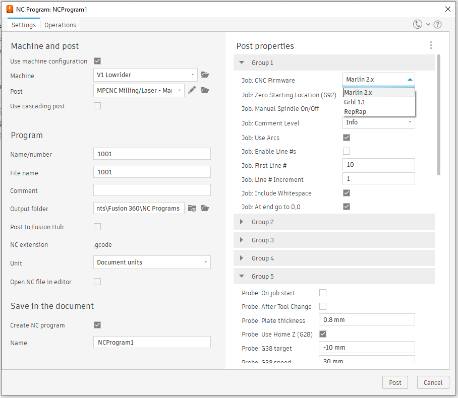
P.S : I have tried the Fusion Post processor (beta3 from Don) but in Fusion I can’t choose what firmware I’m using for this Post processor.

The flyfisher pp is the only one I’m aware of that’s been shared publicly.

Thanks!

But in Fusion, how can I choose between Marlin and Grbl, when I install the pp? How can I tell to fusion what firmware am I using?

From the documentation:

Use the Job: CNC Firmware property to select between Marlin 2.x, Grbl 1.1 and RepRap firmware

Disclaimer: I don’t use Fusion cam so no idea if this works

1 Like

Welcome!

BTW what does the Fusion post-processor do? Can you instead take your design from Fusion and create your gcode in Estlcam?

It replaces estlcam, you generate the gcode for the machine directly from fusion.

Hello, I want to use Fusion or Vcarve to generate paths and gcode because I want to carve models on the two sides, and I don’t think that Estlcam is capable of that.

I have searched on YouTube for carving two sided models, and I fondant found anything about that.

Sorry for my English.

2 sided milling relies on you using registration so when you flip the work it is correctly aligned, I have sucessfully done this using estlcam.

1 Like

marlin postprocesor for vectric aspire.

Here you go

Thank you! This seems to be working. I had to make some modifications to the post-processor to suit my machine and my specific needs. I’ve already created a test file in Aspire 12.5 and exported the G-code to CAMotics, and everything looks correct. Now it’s just a matter of experimenting once the machine is ready.

I’ll share here the Vectric post-processor I’m using for my CNC, along with the workflow.

WORFLOW:

Header / Initialization

  • Sets absolute positioning (G90) and millimeter units (G21).

  • Homes the X/Y axes via endstops (G28 X0 Y0).

  • Sets the current position as the work origin (G92 X0 Y0).

  • Displays the name of the toolpath on the controller (M117 [TOOLPATH_NAME]).

  1. Rapid Moves (G0)
    • Moves the tool to start positions without cutting.

    • Uses combined [X][Y][Z] placeholders, moving to the next point quickly.

  2. Cutting Moves (G1)
    • FEED_MOVE: Moves the tool along the toolpath at the cut feed rate ([FC]).

    • PLUNGE_MOVE: Moves the tool in Z at the plunge feed rate ([FP]) to safely reach cutting depth.

  3. Arc Moves
    • Clockwise (G2) and counterclockwise (G3) for circular paths.

    • Helical moves include Z-axis movement combined with XY arcs.

  4. New Toolpath Segments
    • Displays the current toolpath name (M117 [TOOLPATH_NAME]) whenever a new segment starts.
  5. Dwell / Pause (G4)
    • Adds a pause if specified in the toolpath ([DWELL]).
  6. Footer / End of File
    • Homes all axes at the end of the job (G28).

    • Displays completion message on the controller (M117 Usinagem completa).

      POST PROCESSOR:
      +===========================================================================
      |
      | gCode - Vectric machine output post-processor for vCarve and Aspire
      |
      +===========================================================================

      POST_NAME = “Marlin MPCNC Manual Spindle (*.gcode)”
      FILE_EXTENSION = “gcode”
      UNITS = “mm”

      SUBSTITUTE = “([91])[93]”
      RAPID_PLUNGE_TO_STARTZ = “YES”
      LINE_ENDING = “[10]”

      LINE_NUMBER_START = 0
      LINE_NUMBER_INCREMENT = 1
      LINE_NUMBER_MAXIMUM = 999999

      VAR LINE_NUMBER = [N|A|N|1.0]
      VAR CUT_RATE = [FC|C|F|1.0]
      VAR PLUNGE_RATE = [FP|C|F|1.0]
      VAR X_POSITION = [X|C| X|1.3]
      VAR Y_POSITION = [Y|C| Y|1.3]
      VAR Z_POSITION = [Z|C| Z|1.3]
      VAR X_LENGTH = [XLENGTH|A||1.0]
      VAR Y_LENGTH = [YLENGTH|A||1.0]
      VAR Z_LENGTH = [ZLENGTH|A||1.0]
      VAR Z_MIN = [ZMIN|A||1.0]
      VAR SAFE_Z_HEIGHT = [SAFEZ|A||1.3]
      VAR DWELL_TIME = [DWELL|A|S|1.2]

      ±--------------------------------------------------------------------------
      | Start of file output
      ±--------------------------------------------------------------------------
      begin HEADER
      “; [TP_FILENAME]”
      “; Material size: [YLENGTH] x [XLENGTH] x [ZMIN]mm”
      “; Paths: [TOOLPATHS_OUTPUT]”
      “; Safe Z: [SAFEZ]mm”
      “; Generated on [DATE] [TIME] by [PRODUCT]”

      “; Modo absoluto e unidades”
      “G90”
      “G21”

      “; Homing X/Y via endstops”
      “G28 X0 Y0”
      “G92 X0 Y0”

      “; Caminho inicial”
      “M117 [TOOLPATH_NAME]”
      end HEADER

      ±--------------------------------------------------------------------------
      | Rapid (no load) move
      ±--------------------------------------------------------------------------
      begin RAPID_MOVE
      “G0 [Y][Z]”
      end RAPID_MOVE

      ±--------------------------------------------------------------------------
      | Carving move
      ±--------------------------------------------------------------------------
      begin FEED_MOVE
      “G1 [Y][Z] [FC]”
      end FEED_MOVE

      ±--------------------------------------------------------------------------
      | Plunging move
      ±--------------------------------------------------------------------------
      begin PLUNGE_MOVE
      “G1 [Y][Z] [FP]”
      end PLUNGE_MOVE

      ±--------------------------------------------------------------------------
      | Clockwise arc move
      ±--------------------------------------------------------------------------
      begin CW_ARC_MOVE
      “G2 [Y][I][J] [FC]”
      end CW_ARC_MOVE

      ±--------------------------------------------------------------------------
      | Counterclockwise arc move
      ±--------------------------------------------------------------------------
      begin CCW_ARC_MOVE
      “G3 [Y][I][J] [FC]”
      end CCW_ARC_MOVE

      ±--------------------------------------------------------------------------
      | Helical arc moves
      ±--------------------------------------------------------------------------
      begin CW_HELICAL_ARC_MOVE
      “G2 [Y][Z][I][J] [FC]”
      end CW_HELICAL_ARC_MOVE

      begin CCW_HELICAL_ARC_MOVE
      “G3 [Y][Z][I][J] [FC]”
      end CCW_HELICAL_ARC_MOVE

      ±--------------------------------------------------------------------------
      | Begin new toolpath
      ±--------------------------------------------------------------------------
      begin NEW_SEGMENT
      “M117 [TOOLPATH_NAME]”
      end NEW_SEGMENT

      ±--------------------------------------------------------------------------
      | Dwell (pause)
      ±--------------------------------------------------------------------------
      begin DWELL_MOVE
      “G4 [DWELL]”
      end DWELL_MOVE

      ±--------------------------------------------------------------------------
      | End of file output
      ±--------------------------------------------------------------------------
      begin FOOTER
      “; Homing final”
      “G28”

      “M117 Usinagem completa”

1 Like

Sounds very good to me, I’ll try to see if I can do the same.
Thanks!

Dual sided carve/cuts are possible with every cam software, you just need to have a custom fence to set x/y zero (and remember to mirror the underside stutt to me done), using that method you can have 4 sided work done on a 2x4 lumber, aluminum tube or anything

Yes, I know, but I want to make guitar necks, and to machine guitar necks where the headstock has an angle, I need to be able to choose the cutting depth in specific areas of the .stl model, and I’m not sure if Estlcam can do that.

I’m not sure if I’m making myself clear, but in Aspire we have the option to select a specific area and choose how much we want to carve down on one side of the model, and a different amount on the other side.

Im a vectric user. I know what you are talking about. Again, you need a fixture that can be set pushed against a fence. A known zero point is your friend. A negative carve for the backside is a must, or the front.

Use 2 sided 3D carve with index pins and a square stock longer than the neck with the index pins in it.

Or I could be totally mistaken i am not a musical instrument person so :person_shrugging:

1 Like