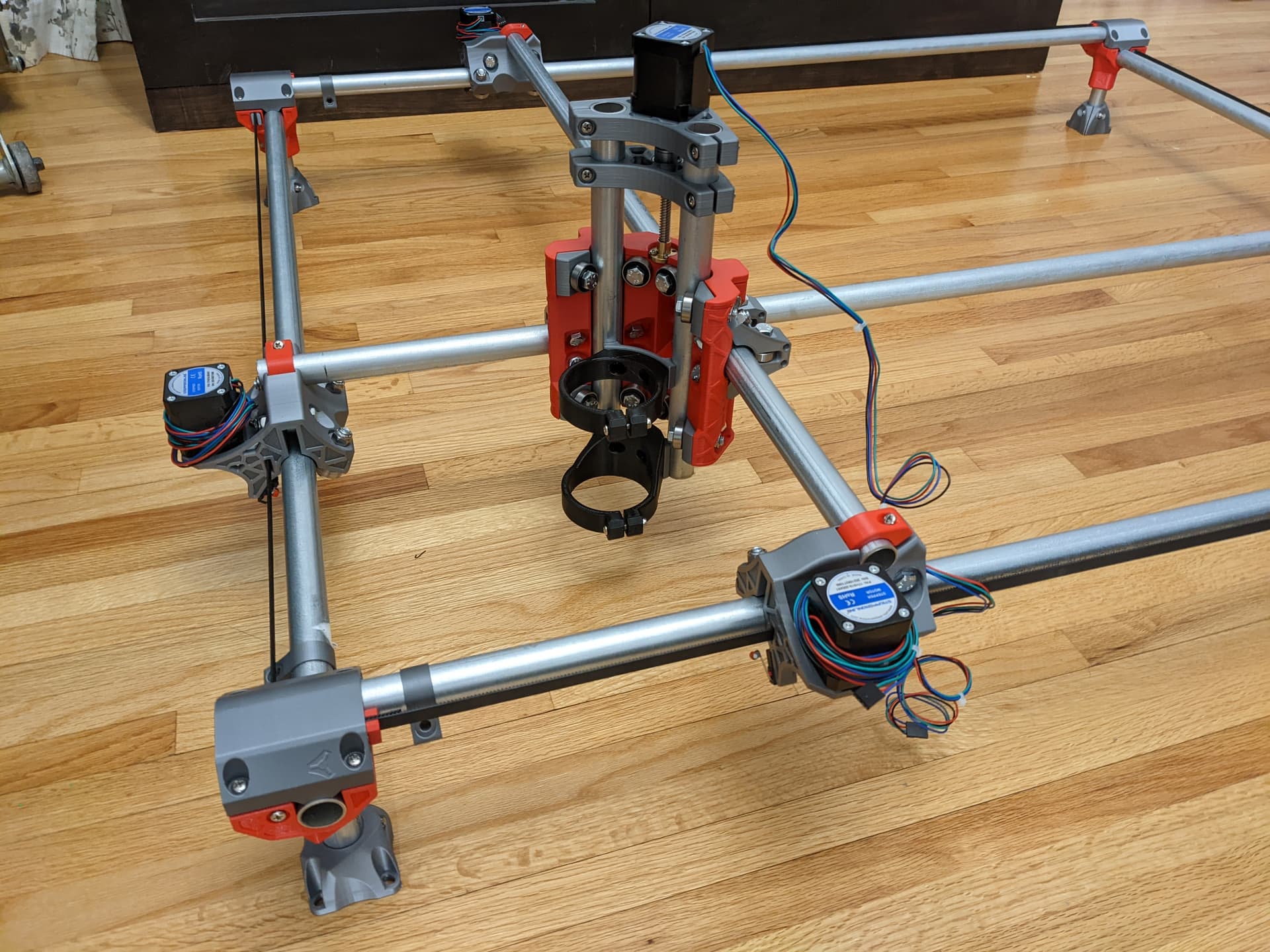
This is my first topic in this forum. I have an MPCNC setup with EMT and an SKR 1.2 pro with the E3 3.5 display. I have not yet powered it up and I’d like to think it through and get it right without damaging anything. I’m trying to establish basic movement and control with dual endstops.
I sheepishly must admit that I may have bought twice as many end stop switches as needed because I thought dual end stops meant there was an end stop at each end of every axis… not super specific, but the controller only has connections for X1,X2, Y1,Y2 and Z axis zero, so the nomenclature is a little confusing to me and I’ve gathered that the “dual” in dual end stops means that each motor of the x and each motor of the y had its own end stop in the home position… so dual motors = dual end stops, one for each motor? Also, I’ve been reading about tape measures in wiring looms to help with cable management. I am pretty good with getting things to work and not so good at making them look nice. After the time spent printing and building this, I’d really like it to look nice and be durable. I have a couple questions on cable placement and flexible cable track. I’m interested in suggestions for how to make the cabling clean and look nice. So here they are:
If the system home is lower left, should the controller be placed nearby the home position (have touch screen controller, so will likely be running it nearby)
If the system is typically moving to home for zeroing at startup, is it recommended that the cables be all bunched up or fully extended when the system is at home? Which will look better? (run the cables through the stationary x axis tube to the far side with the flex cable tray extended completely for homing vs looped back at home)
Do the wires for each axis motor need to be similar length?
Is it suggested or best practice to run the wires on the system side opposite the user and have the cable tray on the far side? (cables go from controller through the left side stationary Y tube to far side, into the flex cable tray for x movement with near motor wires running toward the user through the moving X axis tube connected to the trucks)
These are probably trivial questions, but it is simpler to ask now and build then to build and wish I had asked and done it differently.
Thanks for any information, tips, or suggestions on how to make the system look good as it gets wired up for initial testing.
For these questions, there isn’t a good reason either way:
Doesn’t matter. Just put it where you like it, or where it is easy to install it.
Doesn’t really matter, but I would make it bunched up when at home. I can’t explain why. I am probably just worried that there will be extra wear when fully extended and you won’t drive all the way to max nearly as often
No.
It is nice to have the front be open, so you can hang material out the front, or more easily place it. But it is also nice to have the wires close to set them up easily or work on them if you want.
And you don’t need endstops on the Z or the max of any axis. The Zmin is for a touch plate to measure the top surface of the workpiece. If the machine hits a limit it won’t hurt itself.
From a “make the electronics work” perspective, it doesn’t really matter. I have my control board on the front right of my machine and I home to the front left.
When I upgraded my Burly to my Primo, I made one wire routing change that I’ve been very happy with. I ran the wire for the front X stepper through the tubing on the truck to the back of the machine, through the cable chain, and then brought it back to the front through the outside rail on the right side. This run is the long way around and required me to extend the wiring, but it left the front of the machine totally open, with no cable chain or wiring to get in the way of reaching my spoil board from the front. I use this open front all the time for a variety of uses.
Thanks for the responses. I appreciate the shared perspective. It helps. I’m looking at drag chain vs cable loom with tape measure within and running the wires through the truck tubes for one of each of the x and y motors. I like the idea of the controller on the right side with home on the left and the front clear. Wires will be on the right side and on the back so the front and left will be clear.
What is the best way to route wires for the z axis? Cable drag chain on top of the Y truck tube?
What about router power (using makita). Are there known issues with not separating high and low voltage cables?
One more thing: is the SKR power input on the left side of the board 12V or is there a 5V input? It just says + and -.
What is the recommended amperage power supply for this system with an skr and 5 motors? I have a 5 amp and a 32 amp power supply that both supply 12 volts that I can choose between to use. With the display and the processor and 5 motors, would they ever be taking an amp each all at the same time?
The power to the motors gets switched to a needed PWM, so it hardly ever uses the full amperage available to it, and it’s almost never that all 5 motors would be going all out. 5A should be adequate, with all 5 motors set to 900mA. That said, I use a 10A supply for my machine, mostly because i don’t trust the ratings on the Chinese power supplies I have.
As a point of reference, Ryan ships a 6A power supply with his kits. Assuming it is a quality 5A supply, you should be okay. The issue (which Dan points out), is that the rating on some of the cheaper supplies might be overstated.
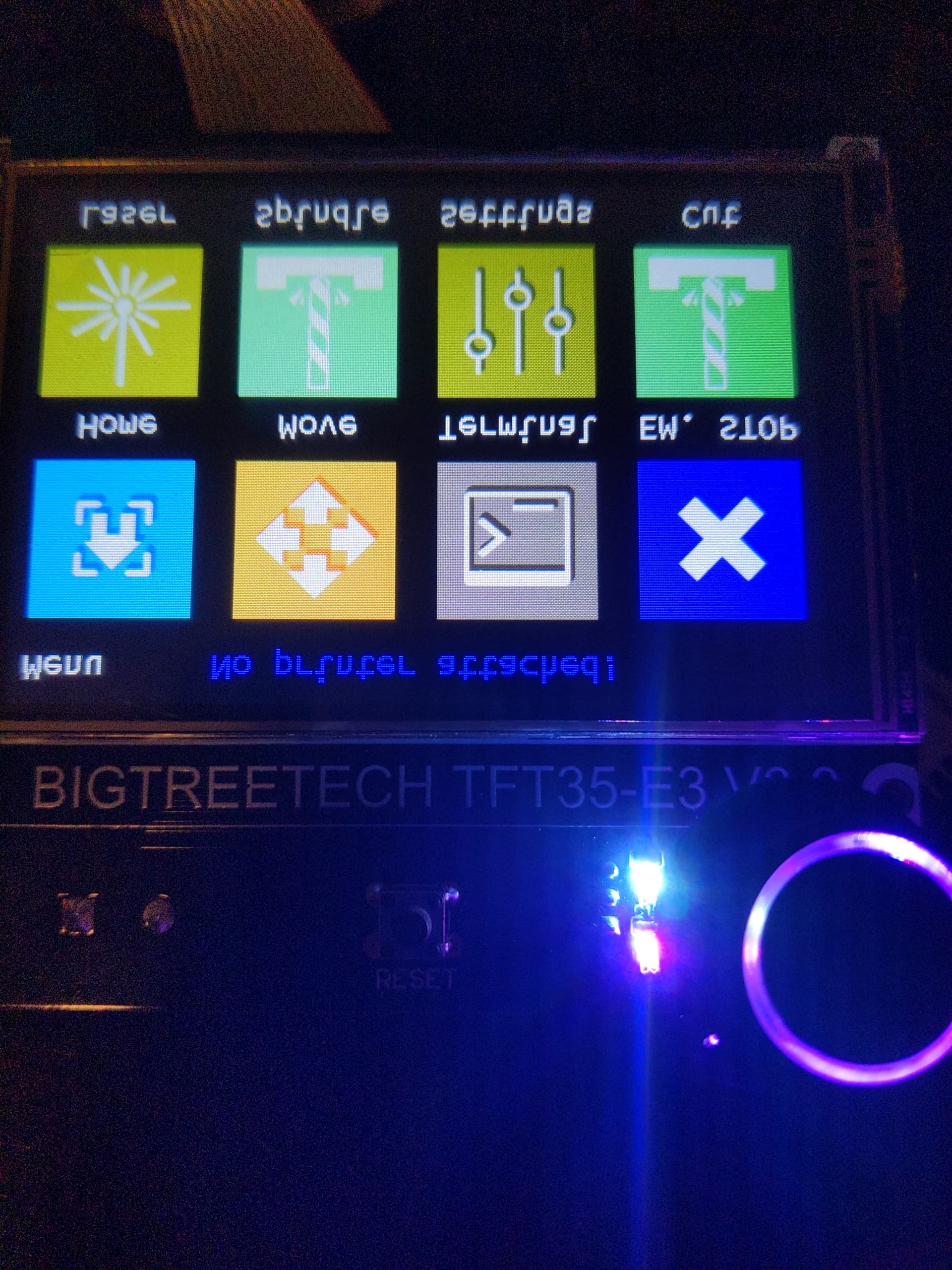
As a follow-up: it is wired and I tested +X goes to the right and +Y goes away from home at the near left side so it is working in Marlin mode from the LCD. I’ll take base functionality for now as drag chains for the cables are printing.
Is Cat5 ethernet cable unwise for the stepper wires?
Solid core wiring is unsuitable (Most CAT5 wire spools) for the motor wiring because it doesn’t like repeated flexing, and will fail over time. CAT5 patch cables made from stranded core wiring have been used with reasonable success.
I used some CAT5 solid core wiring in similar projects for point-to-point wiring where it does not need to flex. This could be used for the span where a wire harness stays inside a tube, like going from the X1 motor mount to the X2 in a Primo, but should be avoided for places where the wire is in a drag chain and flexing as the machine moves.
Ok, so I have stranded wire, printed some cable drag chains and I’m wondering how is everyone else doing this?
If I put a drag chain on the router mount, how does one connect it to the carriage and what does it mount to on the other side? I see some have put in a channel that rides next to the Y movement bar, but where do they connect on the trucks? I saw a burly system with cable chain mount that used the bearing bolts or maybe the idler bolts as anchor points for the drag chain. That makes sense, but they are facing the wrong direction on the trucks for the primo to be used the same.
How are the rest of you connecting cable chains to the trucks? I’m not really interested in drilling into to side of the truck since they look so nice, but if that is the best option…
It would be good to see what makes sense and what you all have learned about this that isn’t showcased.
I designed a mount for the chain that glues to the truck. I used contact adhesive since I expected to go through several prototypes and wanted to easily remove the bracket, but the first prototype worked well (surprise), and I’ve never had an issue with the adhesive. Attached is a ZIP file containing the mount in both STL and STEP formats. Depending on which trucks you select for the chain, you may need to mirror the part in the slicer before printing. The nut traps are for #6 nuts, and I printed it on its “side” with the dip on the top edge. CableChainMount.zip (38.1 KB)
Thank you for the file! Your printing instructions were clear, so I have it sliced and ready to start. I’m unclear how they mount on the truck though, but perhaps that will become more apparent when I have one in hand to mock up. Thanks again for the quick response! I also just came across this post that has a few other ideas.
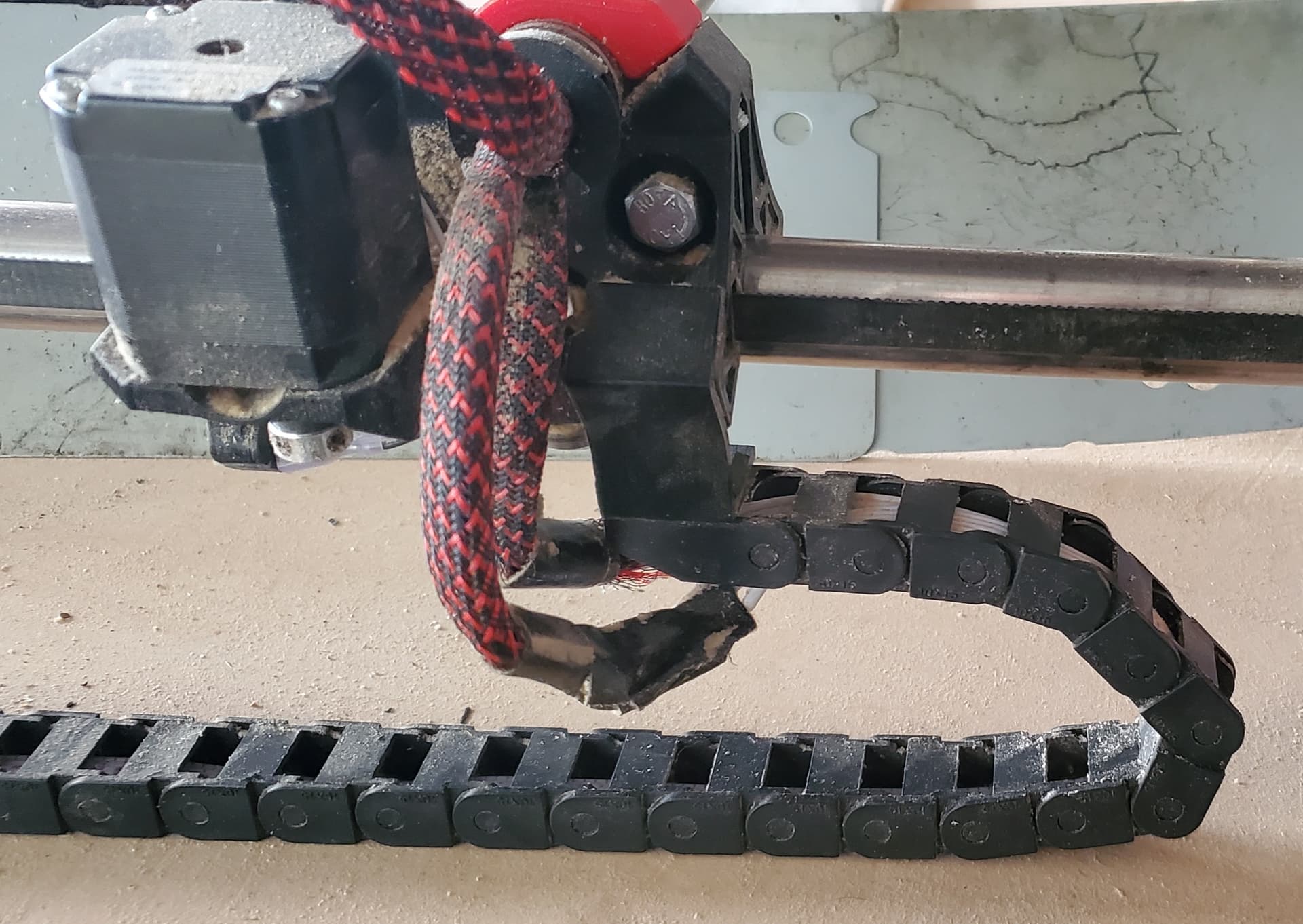
Here is a snap of the bracket mounted. Black on black make it difficult to see, but if you hold the bracket to the truck, the reason for the dip will be clear. Note this bracket was created for this specific cable chain using the spacing of the holes in the mount end. You may have to modify the last link in your cable chain to match the hole spacing, or simply glue the last link to the bracket, or maybe it will be a match.