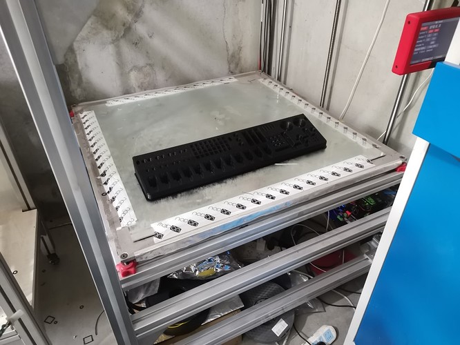
MPCNC Made In China: New Build!

Yes I was thinking the same thing, I’ll probably try it later since it won’t be very difficult to swap those motors.

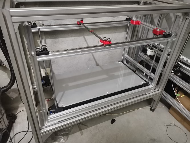
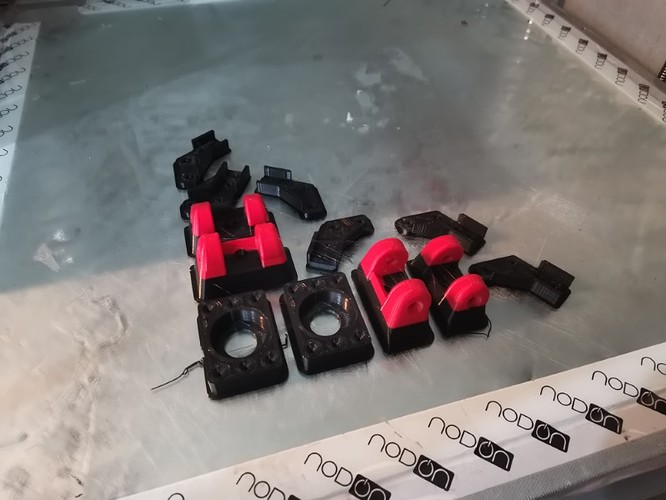
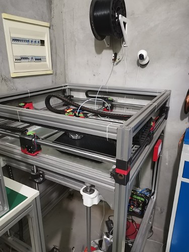
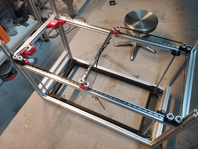
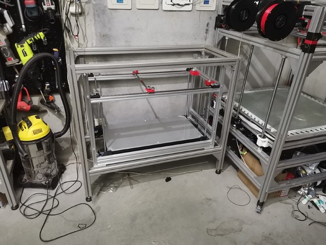
Anyway, I started the build:

The design is not finalized, I’m kinda building it by trial and error this time. But so far it seems ok.
Only thing I’m afraid of is that I went for a very beefy bed (a 10mm aluminum plate), which weights 9 kilos. I’m not sure those tiny steppers will be able to lift it without any kind of gearing down. Guess we’ll see, if it doesn’t work right away I’ll do the same thing I did on my other printer: using pulleys and a belt to change the ratio.

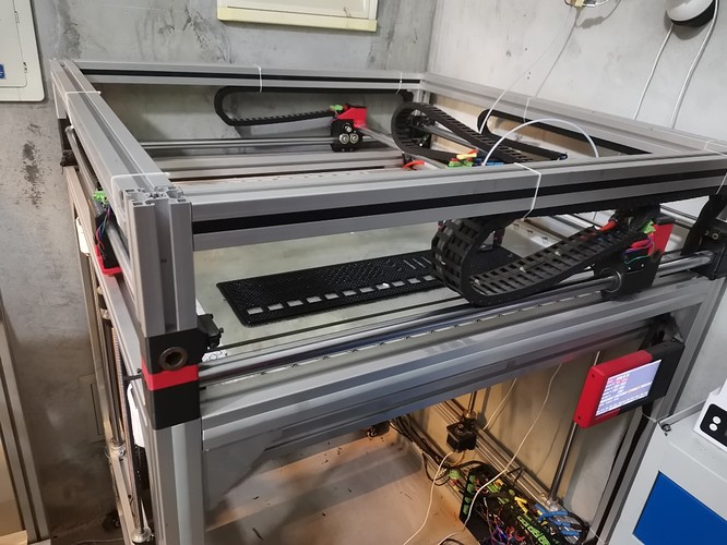
I had no space in the shop for it, so I’m also building a new bench. The printer will sit inside it, I should be able to use the bench to enclose the printer with acrylic sheet later if I want to.

It’s not as huge as the BOx, but for a coreXY it’s pretty darn big.

Anyway, still building!

12 Likes

Hi guys,

A few updates,
First, during the last week I took apart most of the BOx printer in order to upgrade a few components. The roller parts had melted pretty seriously because of the stepper’s heat, and I had some cracked parts here and there since the beginning.
I forgot to take pictures of all that unfortunately, it took me a whole day from early moring up to very late at night.
But now it’s back together and printing better than ever, all good!

Someone asked me this weekend so I counted, and it seems I’m now only one spool away from celebrating 60 kilos of material printed with this machine since I finished it. It works insanely well, I can’t be happier, I can’t remember when was the last failed print due to the machine.

Some parts I printed for work this weekend (the weird bi color scheme is only because I didn’t have black filament anymore). Took about 4-5 hours to print these. I printed a full kilo on saturday with many big parts

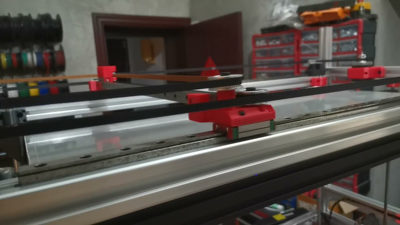
Anyway, also made some progress on the CoreXY. It’s moving on all axis now.

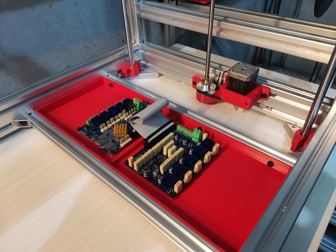
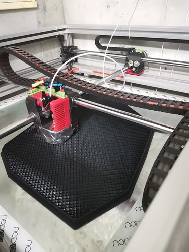
Installed the Duet2Wifi and the DueX5 boards. This big red tray was printed on the BOx (took a bit more than two hours):

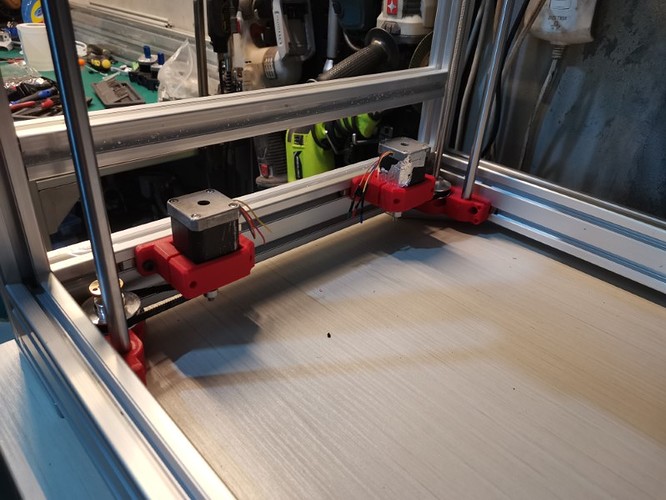
Made a first version of the Z lifting system, very basic but so far it works well:

The Z axis is a bit slow due to the very heavy bed plate (about 10 kilos) and the high demultiplication (I’m using big pulleys and also 1mm pitch lead screws), but it lifts the bed without any trouble and I can tweak the belt ratio later to get more speed if I need it, or go for a lower microstepping rate.

The X and Y axis are lighting fast though, these moves were done at 800mm/s and 20k mm.s2 accelerations.
This seems to be the maimum top speed it can reach reliably at this microstepping rate, but the accelerations could go higher.

(I can’t seem to be able to embed this video in the post, don’t know why but it’s very frustrating) Heffe: it has to be on its own line, with empty lines above and below. Or maybe it wasn’t public at first?

But this isn’t really meaningful until I got the print head installed, because it’s mass will determine what kind of accelerations I can realistically go for. I aim for about 10k mm.s2, that would be a nice achievement already.

I’m currently working on it, I try go get it as lightweight and compact as possible but still packing the most cooling I possibly can (because cooling is key at high speeds)
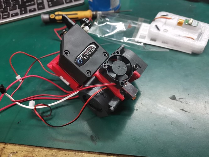
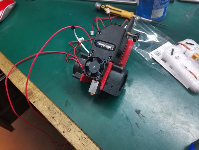
I’m using a volcano nozzle, this time it will be air cooled because of weight concerns, and I’ll use a PT100 sensor to get more accurate temp reads. Some big blower fans on each side for part cooling, I’ll make some kind of shroud to direct the air in the proper places. A plastic dual gear extruder since you guys totally convinced me that those are the bomb, I never had any extrusion problem since I installed one on the BOx. Using one of the smallest steppers I could find to lower the mass (20mm thick). Last but not least, it will have a BL touch for bed leveling. So far the weight is a little bit under 300grams, I don’t think I can make it any lighter than that with regular 42mm steppers. Hopefully this won’t be too heavy…


I’m now wondering about the wiring to the print head, I want that to be as compact, flexible and weighless as possible so I’m thinking about experimenting some wires with very thin insulation.
6 Likes

After working on this style myself for a while. Your XY design is about as elegant as it gets. I freaking love it. For those crossover pulleys in the back might need to add a top to increase strength? The speeds and accels you run might really yank on those.

If my giant abomination doesn’t work smooth, I am gonna do it your way.

2 Likes

That is the total with everything so far? Extruder, hot end, fans, BL? Shoot that is great the hemera is something like 388g plus part cooling and BL.

1 Like

Thanks Ryan, your comment made my day ! :smiley:

Yeah I’m wondering about this too, there is a big M5 screw going all the way inside those little corner parts, which acts as reinforcement, but I don’t know how these will hold on the long run.
I’d prefer to avoid adding a top part (and I still have another way to avoid this), but I might have to. Hopefully not, but only time will tell.

Yes that’s the total weight including the stepper motor, the bondtech extruder, the hotend, hotend cooling fan and shroud, part cooling, wires and brackets. That doesn’t include the BLtouch since I haven’t installed it yet.
But It will be heavier, I still have to make a shroud to direct the air for part cooling, to add insulation on the hotend, and to add a little PCB… which should be the first part of an interesting journey too: I want to have the wires as light and free as possible, meaning I want to get rid of any drag chains.

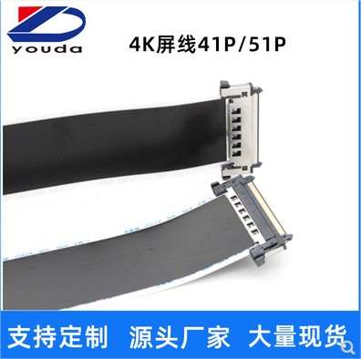
So I had this idea yesterday of trying to use a flex cable instead of a regular multi wire cable.
Something like this:

FFCLVDS4k41P51P - - Google Chrome

The advantages are obvious:
-super lightweight
-super flexible
-very easy to disconnect (which can be useful later to make tool changing, maybe)
-Should stay straight if oriented perpendicular to the floor, meaning I could avoid using drag chains entirely for the print head.
-Super cheap, much cheaper than a regular cable would cost me.

I don’t know if there is any inconvenience, I guess I’ll see. I expect it not to be able to take lots of current, but with 41 or 51 pins I can easily parallel a few pins to carry the necessary pixies to the hotend without burning everything, hopefully.
I know it should work just fine in theory because my Qidi X-Plus printer uses this kind of flex cable for the hotend, I just hope it will work on my printer because it is much bigger, so the flex cable has to cover a much greater distance without falling down

Anyway, we’ll see how that goes,

2 Likes

It will depend on how tight you make your belts to have to use double shear for your pully screws. I don’t have it on my railcore, but a few of the guys that go with high tension on the belts had to put cross braces on theirs.

1 Like

Thanks a lot for your yelp as always heffe, I tried everything I could for at least 20 minutes, it drove me nuts XD
I did try having empty lines before and after, it was set up to public and I also made sure it was set to allow embedded videos in youtube parameters, no idea what was going on :thinking:

IDK. Happy to help though. Embedded yt videos are the only forum super power I use.

1 Like

Quick, call Billy Butcher!

Still working on my print head, making some fun experiments to reduce the weight.
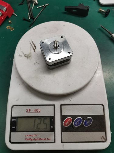
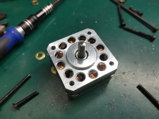
I took a 20mm pankake motor:

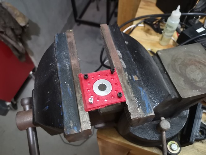
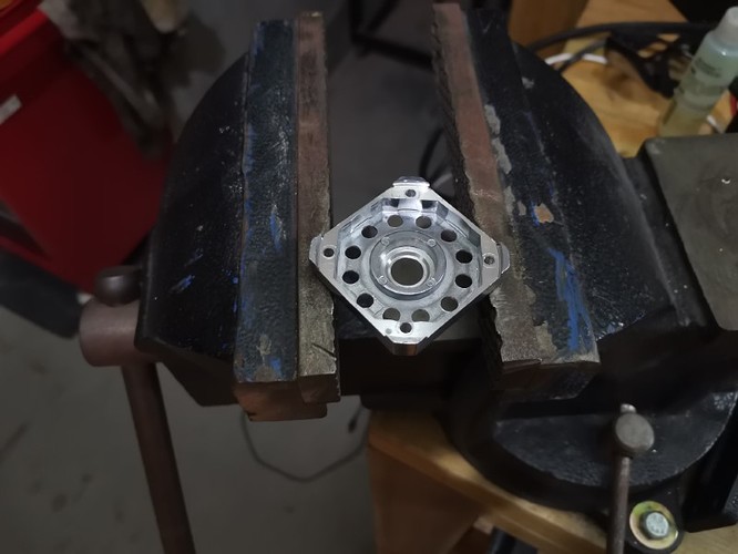
3D printed a smal template, then drilled holes all over it:


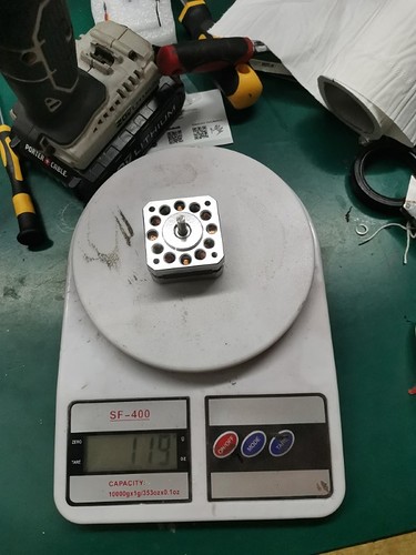
And tadaa, 6 grams are gone XD:

I suppose it might help also cooling slightly, but obviously the most important point is that it looks much cooler :stuck_out_tongue_closed_eyes:

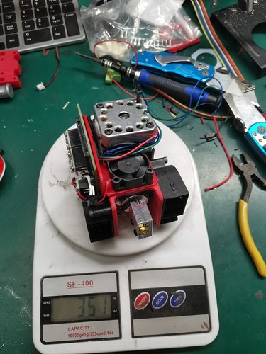
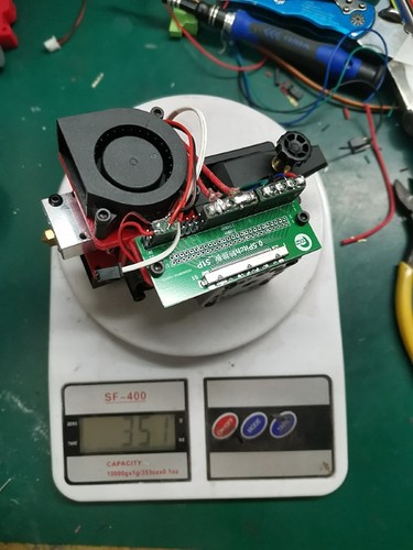
I also received my flex cable connector breakout board and installed it on the printer. Now the print head is almost completed, I’ll just have to add the BLtouch and the fan shroud:


So far that’s not too heavy, and I think I can lower a little bit the weight by removing material here and there. But that’ll be for later.
Now comes the hard part, which is wire management to the print head. Unfortunately my original plan which was to run a single flex cable from the frame to the print head won’t work. Reason being that the cable isn’t rigid enough, so it falls down because of gravity. So right now I’m trying to find the best solution to overcome this issue.

I’m hesitating between two solutions, one being to make some kind of thin cable chain so I could still go for the original plan, but I fear that this chain will be heavy and create some artifacts while printing, due to it’s mass and the forces it’ll exert directly on the print head.

The other solution is to imitate the setup we have on the MPCNC, with cables running along X and Y axis instead of directly in diagonal from the frame to the head. So that would mean having a long flex cable (or just regular wires) coming up to the Y axis, then a shorter flex cable going to the head. That would lower the forces on the head, but I’d then need a long cable chain running all along the X axis, which I wanted to avoid in the first place. I’d also need to place either a breakout board or a custom connecting PCB on the Y axis roller, which isn’t super convenient.
So I’m kinda stuck in this dilemma right now, both solutions are likely to work just fine, but none are really the ideal I was going for.

7 Likes

Wire management, you say? Well, tape measure trick, I say! :wink:

Sorry, I couldn’t resist. Much like Seiji Ozawa… :clown_face:

2 Likes

Well thanks mate, haven’t thought about that trick at all !!
So yeah, I guess I’ll give it a try. That won’t work with my original idea, but it will work very well for sure with the second option I explained above.

Thanks again for the great idea!

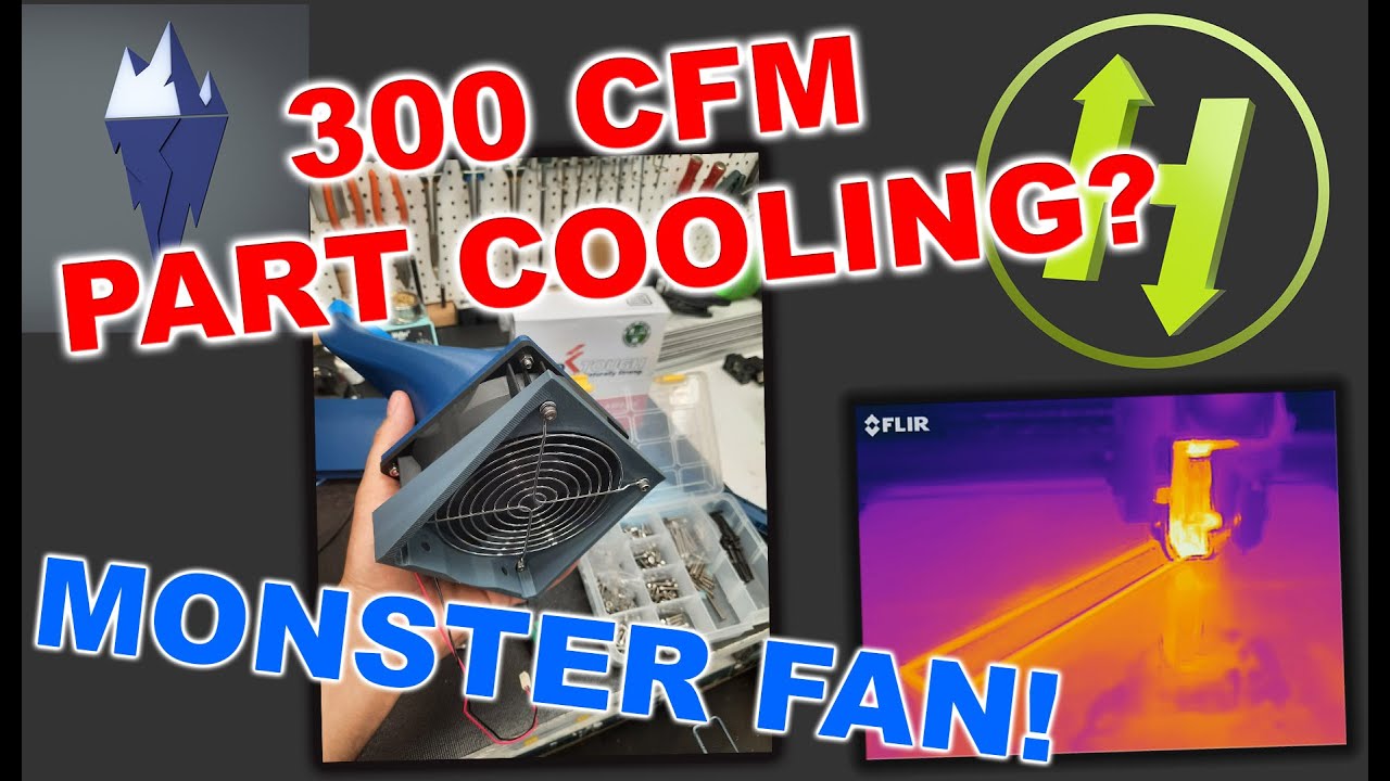
Have you considered removing part cooling from the print head assembly and blowing across from both sides like this:

That may remove some print head weight and still provide fantastic cooling?

1 Like

That’s an interesting video. it would be a bit difficult to fit this system on my printer, but I’ll keep it in mind. Cooling is indeed one of the most important things to consider if you want to print quickly with decent quality.

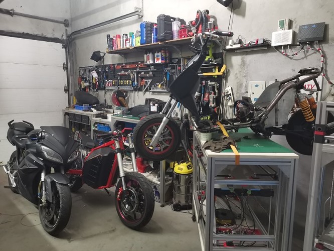
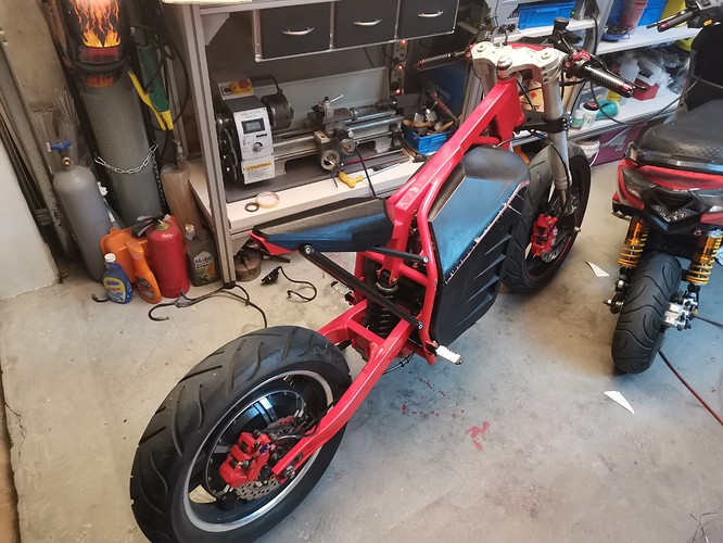
Anyway, I had to pause the project for a little bit, my motorbike’s battery has a problem so I’m building an electric scooter to be able to go to to work while I’ll send the battery to be repaired in a shop that has the equipment to do it. Right now the printer serves as a table on which I’ve put the scooter. It’s much more convenient to work on it this way.
Hopefully that won’t take more than a month,

3 Likes

I can’t decide if it is offensive to use such a beautiful machine as a workbench, or amazing that you can put a vehicle on your printer. I am offended and impressed. :slight_smile:

13 Likes

That’s a familiar sight for me. Lots of projects that require other projects to complete.

What steps per mm setting are you using for the BMG clone extruder? I updated my firmware and lost all the values a good ballpark figure would be nice before dialing it in.

Ok the scooter is now done, so I will start working on the printer again very soon.
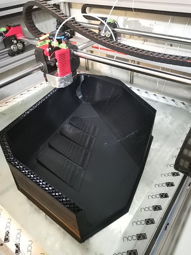
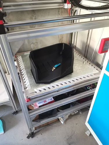
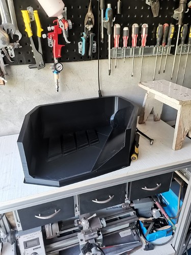
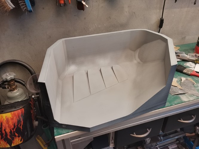
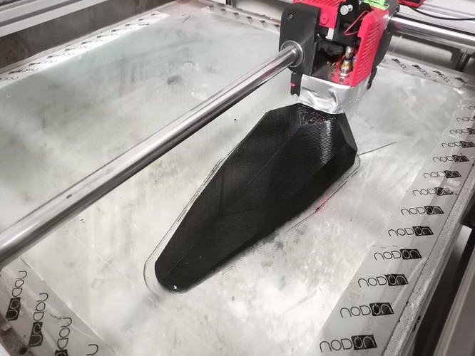
But meanwhile, I printed the biggest stuff yet on the BOx, it is a big mould in order to hopefully make some carbon fairings for my motorbike:

It was my biggest print by far, about 2,5kilos of filament

Got myself a huge 5kg spool for the occasion:

I had a little issue on some layers, because I hadn’t tightened the extruder screw properly (stupid mistake…), so the filament was sliding on the gears. I solved the issue mid print and from then the rest of the print went perfectly.

The total print time was just a little bit under 40 hours. This thing is freaking huge.

Had no trouble to remove it from the glass after it cooled down. Also, no warping whatsoever. The result is exactly what I was expecting.
A bit of sanding, some filler, some primer and it’s almost ready now. I just have to find some kind of gel coat and it will be done.

Also made a relatively big print out of flexible TPU filament: it is a test saddle for the motorbike.

TPU is a bit tricky to print, I had mostly successes but sometimes it fails because the nozzle clogs. I haven’t found printing parameters that guarantee me success everytime, still need to work on that. But when it doesn’t clog it works pretty well and it is not too slow. This part took about 13 hours to print, it’s longer than PLA for sure but it isn’t that bad considering its size.
This saddle is much more comfortable than the one I made out of PLA, but I will experiment with different infills shapes and thicknesses to make it as comfortable as possible.

Anyway, the BOx still works really, really well. The new design of my rollers is really nice, the motors are actually very hot (to the point it litterally burns my fingers if I touch them), but the rollers haven’t deformed even after hundred of printing hours. I’m really impressed.

12 Likes

Not much progress to show on the CoreXY, I’m working on the wiring and sltghty redesigning some parts in order to accomodate for the cable chains and whatnot.
This time I prepared the wiring for dual extrusion from the start. Won’t do it immediately but at least it should be easy to upgrade since the wiring will already be ready.
So right now I’ve got nothing to show on this front.

But I kept printing stuff with the BOx anyway, and after I tried a few different infill patterns and thicknesses, I came out with this saddle made of elastic TPU which is almost the final design.

Well, this is perfect, I’m super happy with this. It feels just like a regular motorbike saddle, you can’t tell there’s anything special about it while sitting on it, it’s no different from a saddle made of foam. The TPU seems to be very well adapted to this application so far. Tha’ts a great win for me because the saddle has always been my worst fear on this project, I wasn’t sure I would be able to make it comfortable while keeping it reasonably small.

So now I just have to find a way to cover it in leather, which shouldn’t be too hard hopefully. The best part about all that is that I can very well design and print as many saddle shapes as I want if I ever get tired of this design!
3D printing is great, there’s always so many new possibilities…

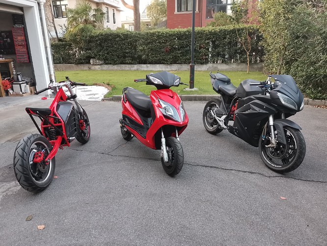
So yeah, now I’ve got 3 electric vehicles… :sweat_smile:

10 Likes

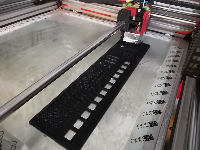
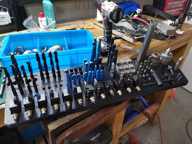
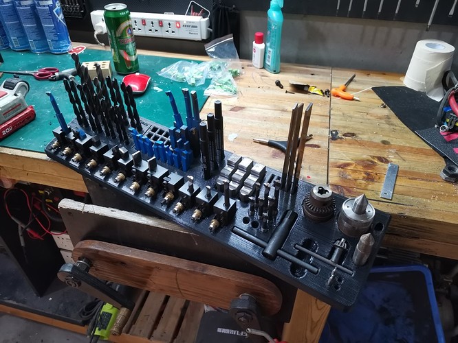
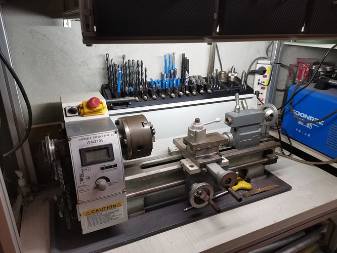
My little project of this weekend: making some kind of tray to better organize my lathe tools:


The part is 600mm long and about 150mm wide. It took a long time to print because there were lots of holes and many features, in total about 29 hours and more than 1 kg of plastic.

Worked just fine though, no problem!

I made a few little dimensional errors in my design so I had to massage a bit for some parts to fit well, but no biggie.
Eventuelly everything fitted just right.


I use to have all this stuff in a drawer, it wasn’t very convenient because I had to search for things forever. Now everything can be reached instantly. Plus I think it looks way nicer.

Funny thing is, I started this whole thing in order to properly store my reamer bits… and well, forgot to design a spot for them, so everything is there except for the reamers. :stuck_out_tongue_closed_eyes:

11 Likes

How nice it is to have a huge 3D printer… that tray looks to be close to if not over 600mm… that would be 2 to 3 parts with joints for me!
Nice project

2 Likes