MPCNC Made In China: New Build!

Hello Everyone,

As some of you probably know, I already made a weird MPCNC featuring many, many mods.
See here for those who don’t know what I’m talking about: My MPCNC made in China

Anyway, after a few years of good service, it was time to make a better version of it. It was working fine most of the time, but it wasn’t reliable enough for my taste, and some things really bothered me, in particular the fact that it wasn’t really square to begin with, due to inaccuracies while building the frame, and also the fact that wood is not the most stable material regarding temperature or humidity variations.

So I started working on a new design. This one has litterally not a single part in common with the original MPCNC, I had to start entirely from scratch. The only things I’m keeping are the tubes, because I already had these in my shop.
I wasn’t sure if I should post it here since it’s basically not V1 design at all, so it’s kinda off topic in a way, but, well I thought I’d share it here because I like the community and it will still somewhat look a bit like a MPCNC because of the tubes and corners.

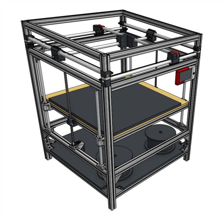
The goals here are multiple:
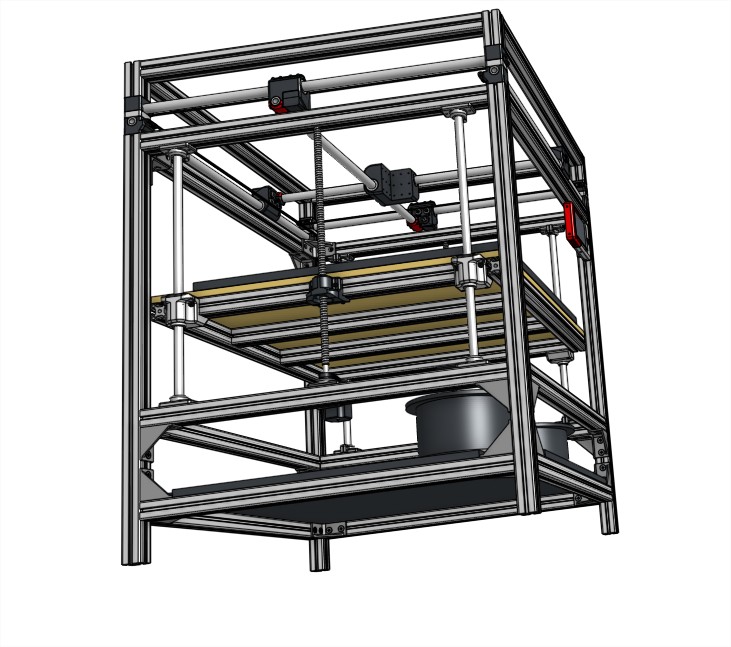
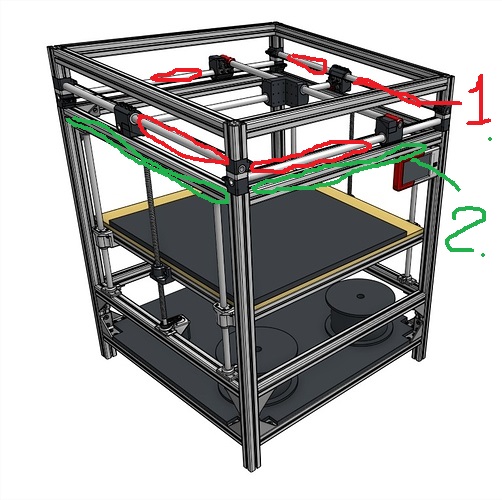
-Have the most possibly rigid gantry system: that implied ditching the Z axis from it. I tried several designs including 4 tubes instead of 2 on Z, semi opened linear bearings, linear guide rails and other systems, but it was just too bulky, complicated and created other issues. So I decided to have only X and Y moving the gantry
-So, as you guessed it, Z will be a moving table, actuated by two or three 16mm ball bearing high precision screws. I’ll first build it with only two screws and add the third one later if it turns out to be necessary.
-Aluminum extrusions frame: I went for 4545 profiles, 4040 was a bit too small to accomodate for the 25mm tubes, and 5050 was really much more expensive. There’s about 22 meters of extrusions in total.
-Duet2 Wifi control board with a huge 7 inches touchscreen. So, unfortunately I won’t be able to use Marlin anymore on this machine, but according to many peole this board is really awesome so I’ll give it a try.
-Better cable management. I’m still not decided yet, but I’ll try to make a better job at cabling, using some lighter stuff since I won’t use plasma cutting on this machine. My only requirements here is that it must look super clean and be easy to disassemble. If possible, off the shelf components, wiring is tedious so I’d like to be lazy on this one.
-Simple tool changing gantry. Right now I designed a system that allows to swap tools relatively easy manually, but later on the goal will be to automatize it.
-Using multiple extruders for color and material changes. I never tried this, but this new platform will be perfect for it.

Main goal is really to achieve very reliable printing at relatively high speed and high accuracy. I want it to be a no brainer machine, launch a print, go open a beer and come back later, if possible drunk, to pick up your print.

Anyway, First thing I had to do was a bit heartbreaking since I had to tear up entirely my good ol’ MPCNC. After so much time and effort invested in it, I felt a bit sad.
mmexport1595211075973

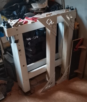
But this will not be going to trash anytime soon, the plan is to convert it to plasma cutting only. I’ll build a water table for it and hopefully it should cut metal before the end of the year.

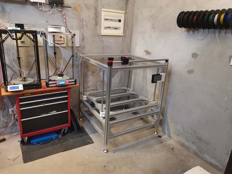
Later yesterday, I received all the necessary hardware for building the frame:

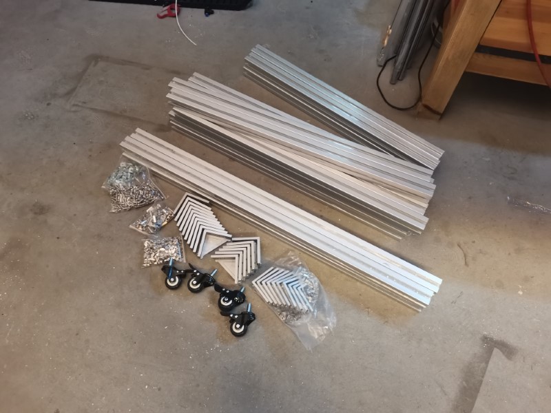
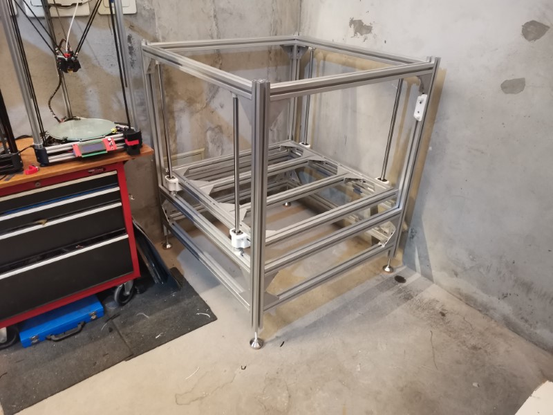
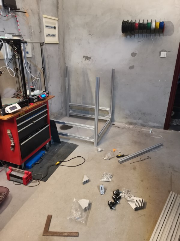
So I started the assembly, which is basically lego, relatively easy to build:

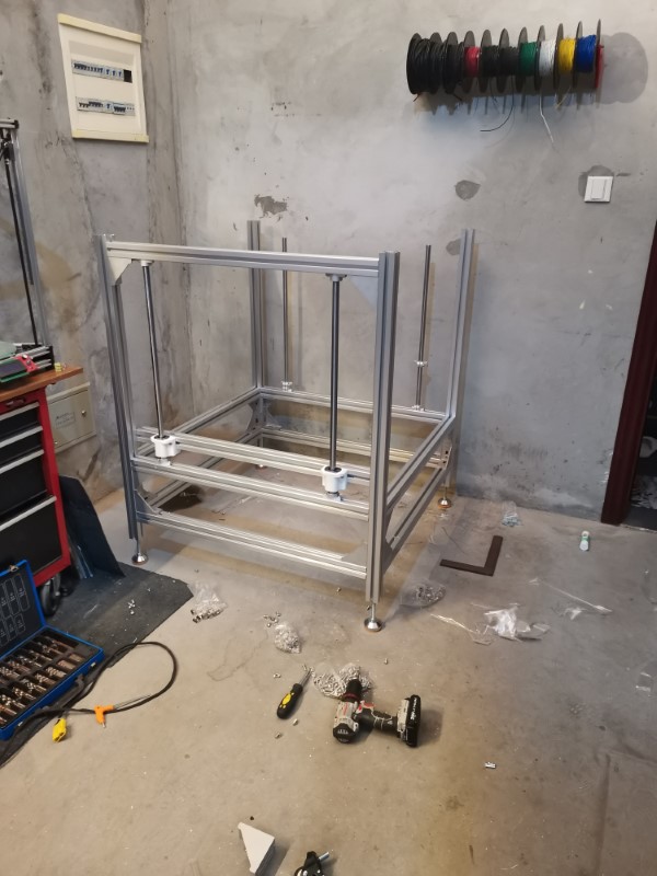
Installed the linear guides for the bed: Some heavy duty 20mm rods with linear ball bearings. I was very pleasantly surprised about how rigid this assembly was. I was not able to feel any play whatsoever lifting one side of the bed frame, the other side followed pretty much instantly. I wasn’t able to twist it either. This is very encouraging because this was the biggest fear I had with this design, now I’m pretty confident the bed will be rock solid! Total Z travel distance will be around 600-700 mm.

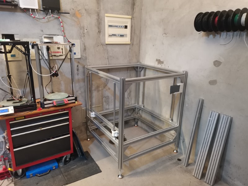
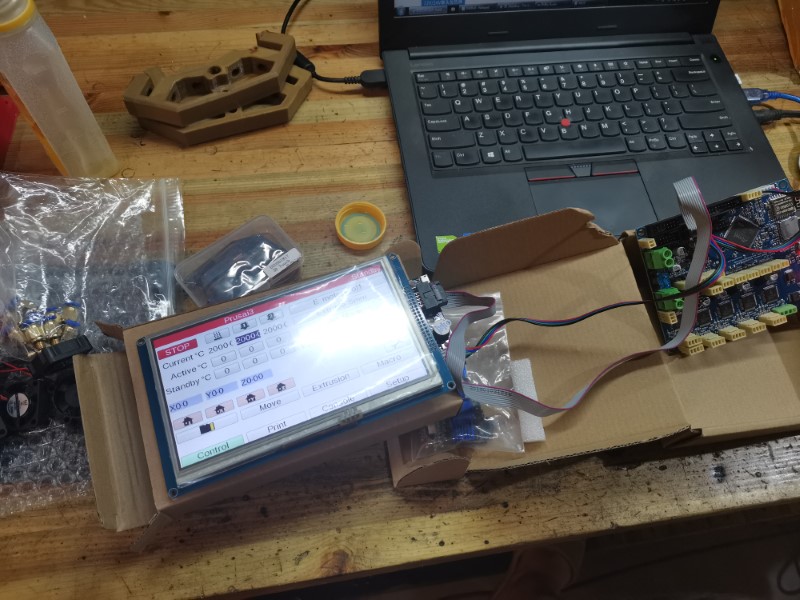
Adding the screen just to see how it’ll look like. Currently printing an enclosure I designed for it so there’s just half of it at the moment:

I tried switching on the Duet just to make sure it worked fine (since this is an expensive board, didn’t want to wait until the machine was finished to discover a potential issue). The screen looks amazing and is quite reactive to the touch. The Duet can be controlled over wifi by a computer, a tablet or a phone, a friend told me later that the screen wasn’t really necessary, but, what the heck, it looks so cool!

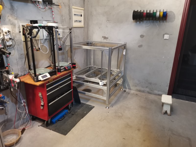
A few more pictures of the beast:


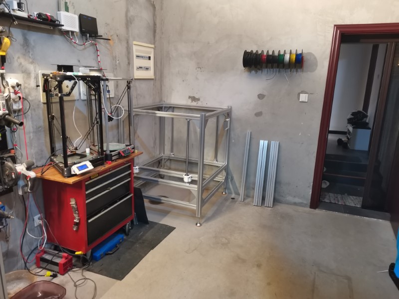
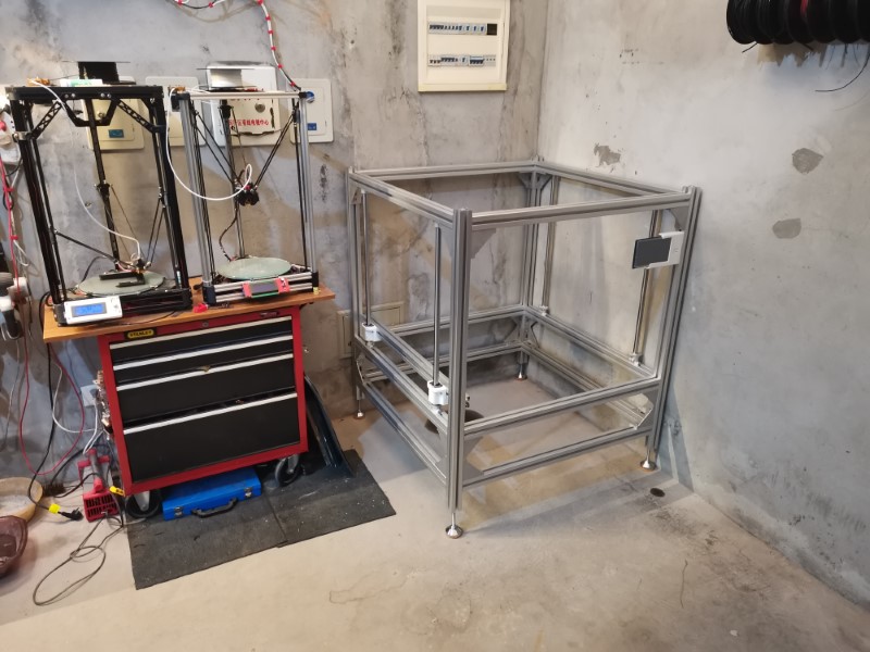
It is really sturdy, this thing doesn’t move at all. Haven’t checked the squareness yet since I have to install the linear bearings on the right side before, The white supports for it are being printed right now.

Footprint is a lot smaller on the X axis but a bit bigger on the Y axis than my previous machine was. But in the end, printable area should be bigger on all axis, I plan it to be around 800x800x650mm or so. It is much more space efficient than my previous version, because the wooden frame was really massive, so that gives me a bit more space in my tiny, overcrowded workshop!

Now I’m printing the other parts and trying to make decisions for the stuff I haven’t purchased yet, like the cables and a few other stuff. I’ll keep posting the progress here if it’s not considered too much off topic, so stay tuned!

19 Likes

Can’t wait to see this thing running!

1 Like

Another with the mad skills​:rocket: or should I say the original :partying_face:

2 Likes

Great as usual. Can you describe a bit more about how you are planning on keeping Z rigid?

2 Likes

Just realised I didn’t even post pictures of what’s the actual design I’m going for…
So here is how it should look like if everything goes well:


The Z axis rigidity is ensured by four 20mm linear bearing rods, solidly bolted to the chassis, plus at least two 16mm ball screws. Wasn’t really sure it would be rigid enough during the design phase, but from the brief overview I got yesterday I’m now really confident it will surpass my expectations by a lot.
Just hope getting the whole thing aligned won’t be too hard, tha’ts still a concern I have.

12 Likes

I can’t wait to watch this beast come together. It looks like a fascinating build.

1 Like

Finished the frame, yay!
Very pleased with how it looks and feels: rock solid!


The bed is quite heavy, but it is really sturdy. I can pick it by any side or corner with one hand, and if I lift it the other side with follow with very few backlash. That’s an extremely good sign it will be precise enough to do what I need!
From what I measured so far, my assembly seem to be precise within a 0.2mm range, which I find a bit unbelievable. I’ll need to do more measurements, but so far it is visibly much, much better than my previous machine.

Now My Delta printers are working full speed to produce all the 3D printed parts, hopefully it’ll be done soon. I’m not in a hurry anyways, still have to wait a while for my ball screws to be custom made.

I’m also assessing different ways for doing a heating bed. My previous heating bed was a heated floor tile. It was working okayish, but it was not able to go over 45 degree C, so a bit too cold. Plus it was taking forever to heat (minimum 30 minutes, but even longer in winter)

I need to do better this time, so far I have several ideas:
-Doing my own DIY heated floor tile: purchasing a marble tile, then making a heating system with some nichrome wire. Problem is I don’t really know how I can attach the nichrome wire to the tile so that it both transfers the heat and doesn’t burn whatever is under it. Some kind of silicon maybe? Plus I don’t think I can find it with the exact size I want, and drilling holes in the tile would be a real pain. Good point is that it would be dirt cheap to make.
-Going for the el classico way: having a custom made cast aluminum plate, and sticking several silicon heating pads under it. That would be cleaner plus it would make flatness compensation easier. Downside would be the cost, I’d need expensive silicon pads given the size, and I have no idea how much would cost a 910 x 910 x 10 mm aluminum cast plate. My guess: more than I’d like to spend…

As usual, good suggestions are welcome :wink:

5 Likes

Electric frying pan or griddle?

1 Like

Damn! That rules out my input…

1 Like

Heating lamps, like those used in heated vacuum presses etc, or just a heater with element and monitor bed temperatureds (crude but cheap).

That was my immediate thought too, but without a heavy, thick heating plate, you’d get hot spots.

1 Like

Also plenty of heat to heat up to 3/4 inch cast.iron button you have to move it😬

I have dollies for that.

1 Like

Thanks for your inputs guys!
Meanwhile, I asked some suppliers what would be the cost for a 910 x910 x 10mm aluminum custom made plate, and it turns out to me much less expensive than I thought (about 90 USD).
So I’m leaning towards this solution, maybe even thicker (but I’ll need to check the stepper motor force before that), using a big plate and several 220V silicon pads under it.

I’ve got another weird idea for the cables. I briefly searched over the internet and didn’t see anyone actually doing that, so I’ll just ask here in case anyone of you already tried it: using USB cables all over, for powering the motor, wiring the sensors, connecting a hotend and whatnot.
The idea being that USB cables are widely available for super cheap, reliable, some of them look like really high quality with breaded sleeves, nice aluminun terminals, they are relatively robust and they exist in verious lenghts.

I’d be using USB 2.0 with regular terminals for the motors, since they are 4 wires, USB 2.0 micro for the endstops, and possibly USB-C for the hotend since it is supposed to be able to bear much more current, plus it has lots of signal wires which could be useful for the probe, the temperature sensors and possibly other stuff like filament sensor, lights, whatever.
Wouldn’t these look sweet?
ewwe

These kind of small PCB terminals would be soldered on the motor leads directly, and integrated in the electronics enclosure at the other end:
-  - Google Chrome

What do you think? Is that completely stupid or is this a possible game changer for us to get clean, reliable, cheap and easy wiring? I’m not too concerned about the current, I tried ethernet cables before and it was working fine so I guess USB should be up to the task too. We’ll see.
I really hope it works, it would make things so much easier!

1 Like

I really want to do this for my hotend. I just saw a video fron teachingtech about the biqu b1 and it uses a usbC for the hotend, except for the bltouch. I would love for someone to make a little pair of boards that connect over usbc and give me all the stuff I need for the hotend in one cable.

Does the aluminum plate need to have any special treatment to make it actually flat? Maybe you are going to autolevel it so it doesn’t matter.

1 Like

1
Good afternoon. You don’t think that element 1 is superfluous in the design. Element 2 will do the job much better.

1 Like

I used to work at a small clothing shop what seems like a lifetime ago now and we used dry-mount presses for thermal t-shirt transfers. Maybe sourcing one and using it’s guts? The one we had was pretty large, at least 24"x24" if I’m remembering correctly.

Edit: Kinda like this…
https://www.ebay.com/itm/Seal-Products-Masterpiece-500T-Dry-Mount-Framing-Mounting-Press/392875477580?hash=item5b79340a4c:g:hG8AAOSwoQZfEKYG

The top half comes off, flip it over, and you have a giant heated flat aluminum plate.

Well, yes and no.
Yes because it is technically possible to do it that way, using some rollers or something running directly against the surface.

No because it would be much less accurate and/or rigid. The rods I’m using are 25mm chromoly rods, made for industrial machines, they are grounded perfectly and are way, way tougher than the aluminum of the frame.
They will never wear, they don’t bend, they provide smooth and silent motion. You gotta love these things!
There’s really not much drawback using them, they are not very expensive either.

So If I had to do a list:
Without these rods:
-Need to design a much more complicated roller support part, it needs to grip the tubes from several planes
-Many small skateboard bearings to purchase
-Lots of screws, nuts to secure them
-Aluminum of the frame will be damaged quickly
-Less accuracy
-Much more complicated assembly: need to measure and adjust height of all the profiles very carefully, the profiles need to be totally parallel to each other, that’s really hard to do (I’m in the process of getting my frame square right now, I can tell you that this is a real nightmare!)
-slight cost saving, around 30-40 bucks maybe in my case
-Dust protection isn’t as good (linear bearing have a protecting seal)
-Far less rigidity

So yeah, they are not absolutely necessary, but in my opinion they were a good compromize (plus I had them already).

Thanks for the answer. Now it is clear.

1 Like

Oh really?
That’s cool, great news, thanks for the tip! So that means it’s doable! Well I just ordered all the stuff to try it so I guess we’ll see, Really hope this works, the wiring will look so much cleaner than my previous one.
Got one color per axis, in several lenghts. I hope 3 meters will be enough for the longest ones, couldn’t find any longer.

I don’t know yet, I just asked a random supplier about a random plate to get a ballpark figure. Usually here in China labor cost or machining costs are super low, so I gess I can have it surface machined for like 10 bucks.
But yeah, I’ll have autolevel, I bought a BL touch clone for that :wink: