Printed a slightly larger version of the enclosure to accomodate the new hardware:
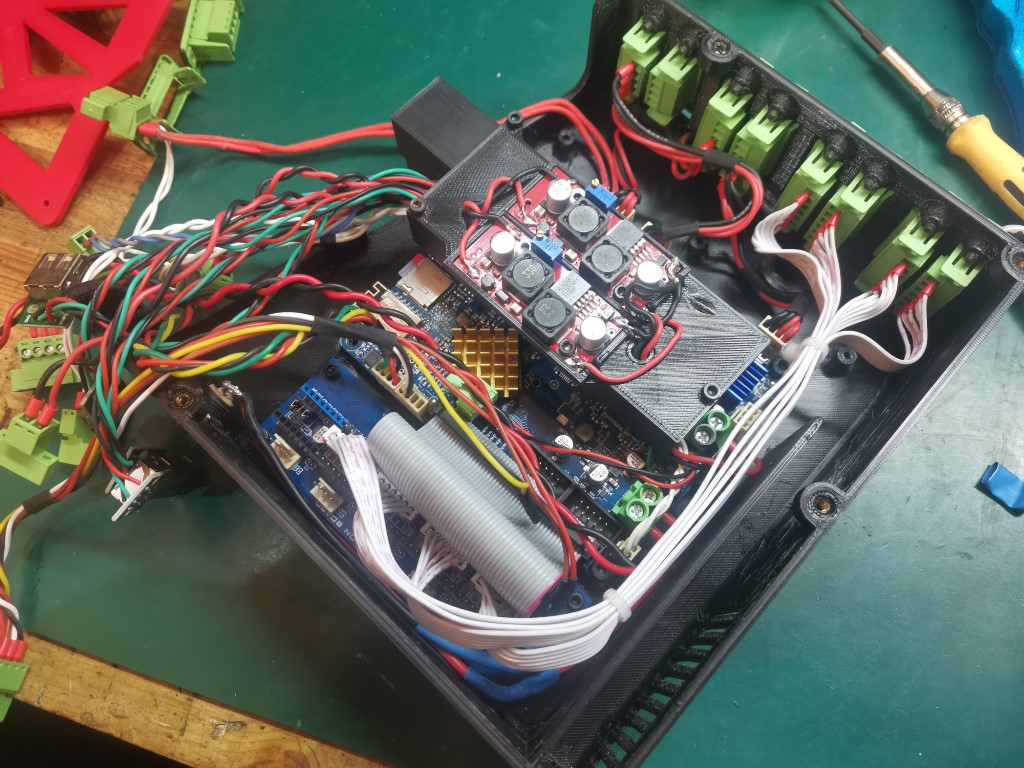
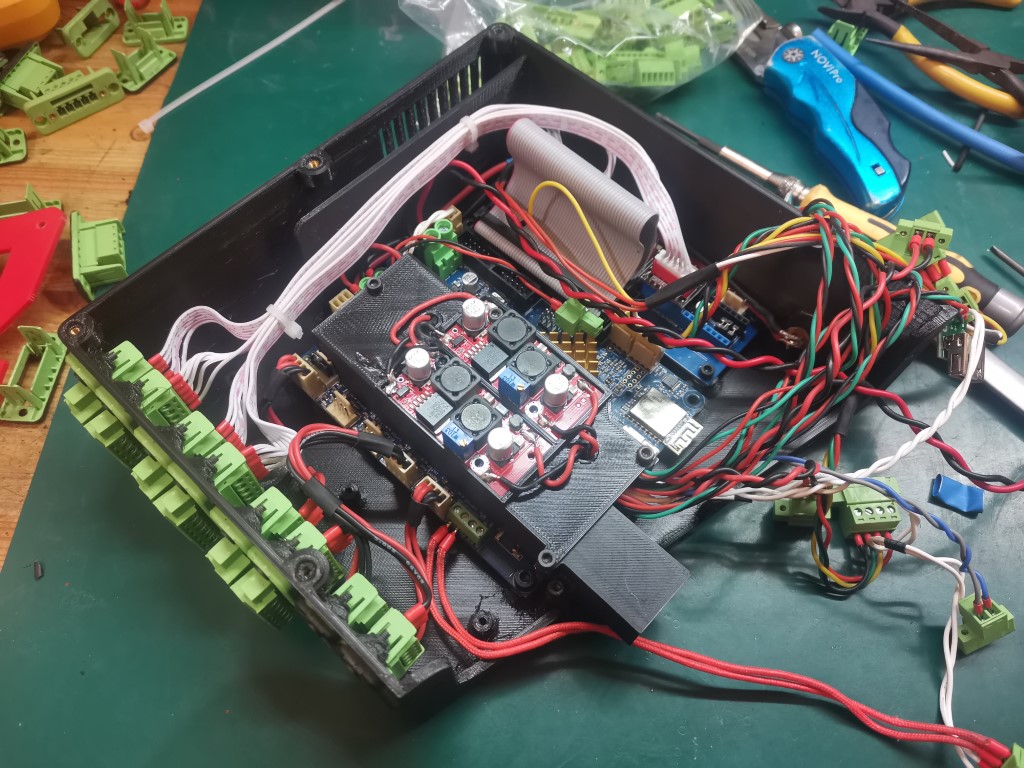
Now I need to start educating myself on the firmware part…
Printed a slightly larger version of the enclosure to accomodate the new hardware:
Now I need to start educating myself on the firmware part…
Ok well the firmware part was very easy, I just had to change the motor port and job done. Took litterally 5 seconds, I was expecting to spend hours on it so that was a pleasant surprise.
I then had to rebuild my whole wiring, which took a few hours. I went for paralleling the motors wires together instead of dual endstop. My printer prints relatively square, so I thought I’d keep the 3 remaining stepstick slots for a triple Z axis using these servo if it turns out to work well on X and Y.
I started by wiring only one motor per axis just to see if it would work and get a feel for the power and speed. And oh boy, I was not disapointed. Here is a short video of a few quick moves. Remember it is just using one motor per axis and my whole print head system weights a ton (more than 8 kilos in total).

There’s just one thing that isn’t great, at least in my particular application, which is that it was difficult to find the correct step rate and top speed. Usually when you tune a stepper motor, you know that you’ve gone too far because it starts skipping steps and you can hear it, it’s fairly obvious. Here, if you go too crazy the motor will try to follow, but I guess the motor controller was too busy to record all the steps that were commanded by the motherboard and instead of moving 100mm for example, it will only move 80 or 95. What’s very confusing is that the error seem consistent and repeatable, it will move the same amount in both direction, so you get the same error all the time.
I had a hard time understanding that, at first so I thought these motors were defective or at least wildly inaccurate, but it turns out I was just feeding them with too high of a step rate that they could cope with.
So what I did was to lower the microstepping to 8 instead of 32, which is done in a few seconds through the motor little screen, and then I was able to get those really high speeds while keeping it precise.
Also, for some reason I don’t understand, I had to change my steps per mm fro 100 to 64. No idea why.
Anyway, the holding torque is just miles ahead my previous steppers, you can’t feel it through the video obviously, but I’m actually pushing pretty hard and this is only with one motor set up at only 2/3rd of its maximum power. It feels so weird to see the head coming back to its position, seems like magic!

At this point I was feeling confident enough, so I decided to go ahead and just do the same for the two other motors, took another hour to rebuild the wiring and then I was able to test.
First test didn’t work, because I forgot to calibrate one motor. I wasn’t sure calibration was necessary but turns out it is, so tha’ts good to know.
After that it all worked well. There is tons of torque and this is about the maximum top speed I can reach safely at this microstepping. That’s very, very powerful. You can see the direction changes and top speeds are pretty impressive:

So now I’ll have to prepare the printer for actual test printings, hopefully this evening if everything goes well.
If tthese motors have the same accuracy as the previous steppers I was using it would be perfect, so I really hope it’s going to work, so far I find these things amazing.
Not sure if your aware, but the fewer microsteos the more torque you will get. So 32 microsteps produce the least torque and full stepping produces the most torque. You can take advantage of that too, by reducing the microsteps so the closed loop controller can keep up but increasing the outside diameter of your pulleys so you gain mm/revolution. You can reach even greater speeds. Of course your trade off is torque. But it sounds like you have that in droves 
Also you needed to change your steps per mm because you changed the microsteping, if you reduce the microstepping again you will need to further reduce your steps per mm, unless you change your pulls size to compensate.
Yeah I know all of that don’t worry, what I dont understand is why 64 steps per mm since there is no obvious reason I can think of for this specific number.
My old steppers needed 50 steps for the exact same travel distance at the same microstepping settings, so that’s weird.
Yeah I figured you knew how stepping worked, but I’m in a mansplaining mood so forgive me.
64 dose seem odd, but also too perfect (being a power of 2) to be a coincidence. But I can’t come up with why it would be different either. Maybe someone can drop some knowledge on us 
I would guess the steps is relative to the encoder, not the poles of the motor, to keep the servo firmware simpler. And then they have a mapping (established during calibration) to convert the encoder positions to the phase of the current through the windings.
I’m confused why lower microstepping would have better torque, since it only affects the format of the commands, and the active side driving the motor should be equivalent.
I am wanting to try these out one day and see if they are much more power efficient (they should be) when operating with low loads.
Oh yes they seem to be much more power efficient. My old motors were much bigger than these ones, yet they were heating pretty fast. So far these one remained totally cold during my tests.
That’s awesome.
I never really thought of that. It pretty much does what the TMC drivers call cool step. That could really make these worth the money. You can turn the max current up because these will only use it when it is really needed keeping things cool and safe. Heck and you can probably use smaller lighter steppers because of that.
Dang Dui, you really have me wanting to mess with some of these.
Please give me an excuse to throw cool techy looking motors like this on my machine
Lol, well so far I don’t have the good news I was hoping for.
First attempt was a complete disaster, the print head was wobbling like crazy, I had insane layer shifts, the two motors on each axis were not even in synch.
I didn’t take pictures as it was just looking like a complete random mess.
On second attempt, I lowered accelerations and speeds. It very slightly improved, at least I was able to see a shape vaguely resembling something. But still total garbage.
As you can see, the thing just wobbles teribly and sometimes get stuck.

So at that point I was really disappointed and I started thinking that those things were garbage or at least not at all compatible with my particular setup. Very frustrating.
But I kept digging and as it turns out the main root cause might be the communication speed between the duet board and the motor drivers. The Duet is configured for working with the TMC drivers, whic havee a very fast communication rate.
The drivers on the servo are much slower, so they need a slower step pulse.
So I tried to lower the pulse timings in the firmware, and this time I did got something actually resembling a print. Sorry I forgot to take pictures since it was already very late and I was exausted, but at least this time the layers were well aligned on top of each other, the motors were in sync and globally it was resembling something.
But I still have a lot of stuttering so there are some very visible wobble on the outside surface, like big waves. I think this is a PID issue because the steppers try to reach the destination and they overshoot because of the very high mass of my print head (lots of inertia). Unfortunately, I’m not clear on how I can edit the PID settings on these particular servos since I haven’t seen anything of the sort in the menus. And as usual, there was no documentation provided with the steppers so I guess I’m on my own.
So, all in all, so far I can’t say if those will work or not. If I can adjust the PID and remove this stuttering that creates waves, then it will be ok, but otherwise it’ll be unusable. So let’s wait a little and see. At least I got them to work, even though it’s very poorly.
Bummer, kinda like the TMC’s and sensorless homing. All that new fancy stuff is complicated and harder to set up than advertised, sometimes it doesn’t always work as promised. In this case I am wondering if something obvious was missed in setup or settings or just some bug fixes need to happen.
Do you know if ‘calibration’ establishes only steps per mm or if it also records some form of momentum or friction that is used for PID settings? Maybe it is tuned with no weight and the large weight of the gantry makes it very different from optimal coefficients.
No Idea.
All I know so far is that you can edit the PID using a complicated process of connecting through a dongle on serial port but you cannot do that with the screen menus, which I found utterly stupid since PID tuning usually is a guess work that takes a lot of trial and error, that’s exactly the kind of things for which the screen would be perfect for.
The other things you can tune using the screen are microstepping or direction, which are stuff you never touch once it’s set up anyay, so I really don’t get what the people who designed these menus were thinking.
I’m trying to find information but apparently few people use these so it’s very hard to find anything interesting.
That’s quite frustrating.
With open loop steppers, there is no logic involved. They don’t ever have to decide if they are in the right place or not. They just step exactly where they are told, until they reach their limit.
With the open loop, it is constantly asking, “is this the right place?” And they are using the sensor feedback to decide. It is more complicated, but I don’t think that is the root issue. It think it is just much harder, and dependent on the quality of the sensor, susceptible to interference, and depends on good software settings.
It may be something simple. I was hoping changing the speed of the interface would help. Or maybe the steps/mm would? It may also be that it just needs some different PID settings. If it is just wiggling while sitting still, then that has nothing to do with the weight of your gantry.
It may also be that it needs some serious firmware updating. That is the nature of the beast.
Well so far it turns out to be a f***king nightmare. It’s insanely complicated to edit this firmware, I’ve spent 2 days on it already and couldn’t get anything working.
I had every possible problem at every possible step.
Had to install visual studio code, and then some add on called platformio which took me more than a day to get barely working with some functions missing,
Had to get myself a Jtag flasher
Had to make some kind of wiring, which didn’t work at first because those morons at bigtreetech made a very confusing wiring sketch.
Had to guess that the product needed to be powered on to be able to flash it, which was written nowhere in the extremely poor documentation
Was finally able to flash the default binary version of the firmware provided by the manufaturer, so at this point I thought it would be ok
Edited the firmware using the source bigtreetech provided on github, using the method they recommend,
Compiled it with no error
Flashed it
Not good, the motor refuses to calibrate and does weird stuff.
Naturally, at that point I thoughtI was the moron, so started back again with the original sources, this time not changing anyting to them and compiling directly.
Flashing. Same exact behavior.
Flashed the original bin file. Back to normal.
So apparently the sources they provide have an issue, which renders them useless after compilation. Great, thanks Bigtreetech, I spent two days for nothing, awesome.
Anyway, it’s horrific to work with, I think I’ll just throw these away, it really starts to piss me off now.
I cannot recommend this product, it’s not user friendly at all. I don’t understand why they don’t bother to add the PID setting in the menu, I saw many users asking for it and they don’t seem to care.
They also seem to say that the PID can be edited in an awful software they made by directly writing hexadecimal (very user friendly, kudos).
Here’s the manual btw:
In order to do that, they say that I “just have to connect the motor to my computer”.
Great, but how???
I have absolutely no idea how I’m supposed to physically connect it, there’s no usb port and when I try it with the JTAG it doesn’t see it as a COM port.
I do see some Rx and Tx labelled ports on the board, so I guess I might have to use these, but how?
I hate chinese companie’s manuals, whoever wrote those useless things deverves a long and painful death.
Any help is very welcome, at this point I’m really stuck.
Probably using a uart usb dongle. A common name is usb ftdi.
But more generally. That sucks. The skills you learned are pretty useful (vscode/pio are strong, flashing over jtag can save some boards). But having an open source product ship with a magic binary is BS. Editing critical parameters through jtag is a joke.
Well as it turn out their binary file is far from magic. I reinstalled the motors in the printer after flashing them with the bin file they have in their repository, calibrated the motors a usual, and then none of them turns anymore when I ask them in the printer interface.
Everything they shared on the repository is garbage and now my motors are bricked until I find a valid version of the firmware. Great job Bigtreetech.
Brutal.