MPCNC Made In China: New Build!

When I hear ‘battery cover’ for a motorcycle I think of something quite small, has a whole different meaning when I see the picture-nice work! :+1:

1 Like

The houses behind the bike in the pic remind me of some neighborhoods I know in NJ. Both the neat things you’re doing with your bike and the houses themselves reinforce my belief that people around the world are more alike than they are different, just another reason why I enjoy this forum. :+1:

4 Likes

I didn’t get to spend much time in China, but from my year in Japan I would say the biggest difference was that the people there were nicer than anywhere I have been in the US XD

But maybe that is just because I was a foreigner :stuck_out_tongue:

1 Like

Yeah, people are nice in China. Though it did change a bit now with the covid.
People are more alike than different indeed, I guess that’s the main lesson you learn from traveling around.

Anyway, the second cover got printed, also in 20 hours and one full spool:


After removing the supports and installed it on the bike:

It printed very well, even better than the first one… except for the first layer: for some weird reason I cannot explain, the first layer is not well bonded with the second one, meaning I was able to peel it off almost entirely.
That’s the first time I see that.
I glued it back on using spray glue so no big deal, but it puzzles me.

9 Likes

That electric motorcycle is looking beautiful. Seeing what he manages to do with his large format 3d printer (which actually looks commercial) encourages me to go ahead in my project of converting my lowrider into a 3d printer / CNC combination. I see the light at the end of the tunnel, now I’m working on the hot bed. I have many projects in mind… :thinking:perhaps too many :smile:

Dude you are a master.

4 Likes

Ok so I’m starting a major update on my machine, trying to convert it to closed loop stepper control.

On very rare occasions, I did see some layer shifts. I know that under some very specific conditions, a certain type of small infills are able to make the printer slipping a few steps. So far, the only solution I had was to dial the speed back, but obviously that’s just lame.

So now I’m going to try and experiment with the bigthreetech S42b v2.0 closed loop steppers, in order to see if I can achieve higher speeds while improving the reliability, without sacrificing print quality.
Sounds like a lot to ask, but I’m curious.

I’ve seen a few videos on those steppers on youtube and they seem to work really well, so hopefully that’ll be the case on my machine too!
Plan is to start using them on X and Y axis, and then later on Z if it turns out to work fine.
Basically anything but the extruder (I do think it is still nice for the extruder to be able to skip step to compensate for problems or bad calibration, if an extruder starts skipping steps there’s usually a good mechanical reason for that to happen, so keep applying more force won’t solve the problem).

Anyway, I received 4 of these motors and quickly tested them:

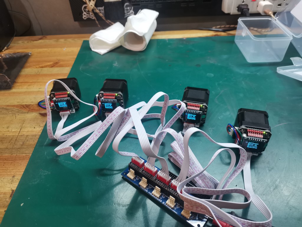
They seem to work nicely, the screen is kinda cute. First thing I did was to calibrate them, which took about a minute (the motor will turn very slowly until it ltells you that it needs to be reset). Then I checked the rest of the menu, which allows you to chose microstepping, maximum current, invert direction and some other stuff.
Pretty neat.
I just wish there were some kind of test menu, where you could ask the motor to perform some kind of sequence (one full turn left, then one full turn right for example), just to see if everything’s in order.
not very important though.

The only issue with these steppers is that, instead of 4 wires, they need 6 wires. So, yeah, you guessed it, I have to redo my wiring for the billionth time… But I’ll also have to redesign and reprint my electronics enclosure as well as a few other parts. So that’ll be a lot of work actually.

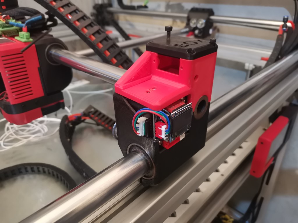
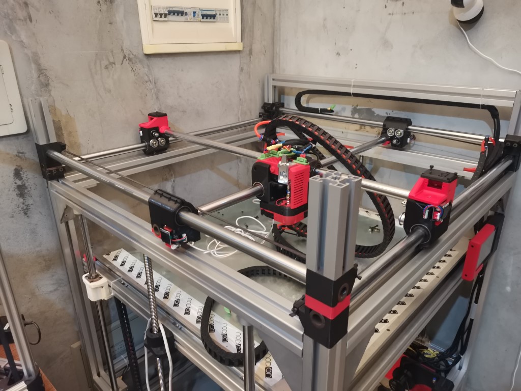
I removed the old motors and installed the new ones:


I’ll prepare the wiring this weekend. I’ll also have to figure out how I should connect that to my duet board and how to modify my firmware. In theory, This extension board combined with the duet allows me to go for 10 axis!
In practice, I’m not sure whether Reprap Firmware allows for stuff like autosquare. If it does, then I’ll use auto square for X and Y, then add a third Z axis (it’s something I planned to do for a while now in order to get the bed perfect), and I’ll still have 3 axis left for 3 extruders. Would be a hell of a machine, tha’t for sure.
But I need to get educated regarding what this would imply in terms of firmware mods, I hope it’ll be simple enough.

Also, I took this opportunity to try fitting a beefy aluminum bondtech style extruder:

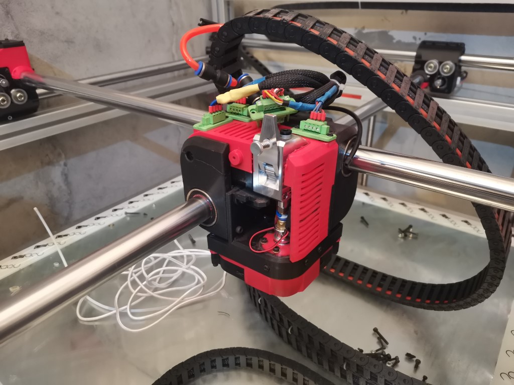
The previous extruder I installed worked well, but it was a pain in the ass to load the filament in it, it wasn’t well guided inside so it was really frustrating. This one being geared and full aluminum, I expect it to heat far less (I had to install a fan on my previous extruder motor, otherwise it was getting too hot, to the point it started melting the carriage)

Now it’s time to start making the new electronics enclosure (I’ll keep the current design, just make it bigger)

9 Likes

It’s a bummer they use 6 wires. I can’t figure out why. Vcc, Gnd, Enable, Step, Dir is 5. Maybe they also want the reset or fault pins or something. Maybe there will be a version in the future with just Vcc, Gnd, and two data pins so we can keep our wiring.

If more people allowed their extruders to skip steps then there would never be a “grinding filament” issue.

1 Like

Good question, seems like they also have a pin labeled “5V 3.3V”
Don’t really know what they mean by that exactly, also not really sure why they would need that since it seems like the board has a voltage regulator already.


They include a 6 wire cable in the package so for people who have a motherboard using stepsticks it’s pretty much plug and play.
Anyway, 5 or 6 wires for me it’s the same problem, but yeah just 4 wires would be better.
Let’s just hope that they worth all this work!

2 Likes

The 3.3 and all that looks like its for firmware development and debugging, SWCK and SWD are used for ARM chip debugging, and then PX1/TX1 are probably for a serial connection for logging (I assume PX1 was supposed to be RX1)

The pink labels on are for a SPI connection for the TFT LCD.

You could actually do a 4-wire connection over CAN-BUS using the CANL/CANH, GND, and 5v, but I don’t think Duet can do that yet. You’d have to do something like a Raspberry Pi running Klipper, and a USB-CAN interface, similar to the Huvud control boards. But that would be a complete restart for your setup, instead of just sticking with your Duet and RRF

1 Like

If the board supported can. We were looking at the 6 pins on the left, and the 5v3.3V pin.

My guess would be step, dir, and gnd would be connected like you would an external TB6600. Then power would be your +12v motor power. 5v3.3v would be +3.3v or +5v power for the driver?

1 Like

That was my thinking. Power is stepper voltage. 5v3.3v pin is digital voltage

1 Like

Strange labelling or not, I appreciate a clean, well designed pinout diagram.

1 Like

Printed a slightly larger version of the enclosure to accomodate the new hardware:

Now I need to start educating myself on the firmware part…

3 Likes

Ok well the firmware part was very easy, I just had to change the motor port and job done. Took litterally 5 seconds, I was expecting to spend hours on it so that was a pleasant surprise.

I then had to rebuild my whole wiring, which took a few hours. I went for paralleling the motors wires together instead of dual endstop. My printer prints relatively square, so I thought I’d keep the 3 remaining stepstick slots for a triple Z axis using these servo if it turns out to work well on X and Y.
I started by wiring only one motor per axis just to see if it would work and get a feel for the power and speed. And oh boy, I was not disapointed. Here is a short video of a few quick moves. Remember it is just using one motor per axis and my whole print head system weights a ton (more than 8 kilos in total).

There’s just one thing that isn’t great, at least in my particular application, which is that it was difficult to find the correct step rate and top speed. Usually when you tune a stepper motor, you know that you’ve gone too far because it starts skipping steps and you can hear it, it’s fairly obvious. Here, if you go too crazy the motor will try to follow, but I guess the motor controller was too busy to record all the steps that were commanded by the motherboard and instead of moving 100mm for example, it will only move 80 or 95. What’s very confusing is that the error seem consistent and repeatable, it will move the same amount in both direction, so you get the same error all the time.
I had a hard time understanding that, at first so I thought these motors were defective or at least wildly inaccurate, but it turns out I was just feeding them with too high of a step rate that they could cope with.

So what I did was to lower the microstepping to 8 instead of 32, which is done in a few seconds through the motor little screen, and then I was able to get those really high speeds while keeping it precise.

Also, for some reason I don’t understand, I had to change my steps per mm fro 100 to 64. No idea why.

Anyway, the holding torque is just miles ahead my previous steppers, you can’t feel it through the video obviously, but I’m actually pushing pretty hard and this is only with one motor set up at only 2/3rd of its maximum power. It feels so weird to see the head coming back to its position, seems like magic!

At this point I was feeling confident enough, so I decided to go ahead and just do the same for the two other motors, took another hour to rebuild the wiring and then I was able to test.
First test didn’t work, because I forgot to calibrate one motor. I wasn’t sure calibration was necessary but turns out it is, so tha’ts good to know.

After that it all worked well. There is tons of torque and this is about the maximum top speed I can reach safely at this microstepping. That’s very, very powerful. You can see the direction changes and top speeds are pretty impressive:

So now I’ll have to prepare the printer for actual test printings, hopefully this evening if everything goes well.
If tthese motors have the same accuracy as the previous steppers I was using it would be perfect, so I really hope it’s going to work, so far I find these things amazing.

10 Likes

Not sure if your aware, but the fewer microsteos the more torque you will get. So 32 microsteps produce the least torque and full stepping produces the most torque. You can take advantage of that too, by reducing the microsteps so the closed loop controller can keep up but increasing the outside diameter of your pulleys so you gain mm/revolution. You can reach even greater speeds. Of course your trade off is torque. But it sounds like you have that in droves :wink:

Also you needed to change your steps per mm because you changed the microsteping, if you reduce the microstepping again you will need to further reduce your steps per mm, unless you change your pulls size to compensate.

1 Like

Yeah I know all of that don’t worry, what I dont understand is why 64 steps per mm since there is no obvious reason I can think of for this specific number.
My old steppers needed 50 steps for the exact same travel distance at the same microstepping settings, so that’s weird.

Yeah I figured you knew how stepping worked, but I’m in a mansplaining mood so forgive me.

64 dose seem odd, but also too perfect (being a power of 2) to be a coincidence. But I can’t come up with why it would be different either. Maybe someone can drop some knowledge on us :slight_smile:

1 Like

I would guess the steps is relative to the encoder, not the poles of the motor, to keep the servo firmware simpler. And then they have a mapping (established during calibration) to convert the encoder positions to the phase of the current through the windings.

I’m confused why lower microstepping would have better torque, since it only affects the format of the commands, and the active side driving the motor should be equivalent.

I am wanting to try these out one day and see if they are much more power efficient (they should be) when operating with low loads.

1 Like