I have tried everything to get my rambo v1.4 working. I have flashed it with the new marlin 2.0 and still it wont communicate with anything. I also have a 2004a screen which all i see is boxes going across the screen. I have tried flipping cables around and every order possible and still nothing. I can connect it to repetier host v2.1.6 but when i am in manual control it wont move the cnc router anywhere. I just need some help I have even tried swapping printer cables out and also swapping the usb ports. If you could help me out that would be amazing and thank you in advance.
Hi Mark! Welcome to the V1 sideshow! I don’t know how much I can help, but I know those who can help will be along in a little while. In the meantime, can you provide some more specifics about your build? Are you using the standard build, or dual endstops? What does your configuration.h and configuration_adv.h look like?
My guess is that you have the firmware misconfigured (not a problem, we can get it sorted out with relative ease, once we know what we’re dealing with).
1 Like
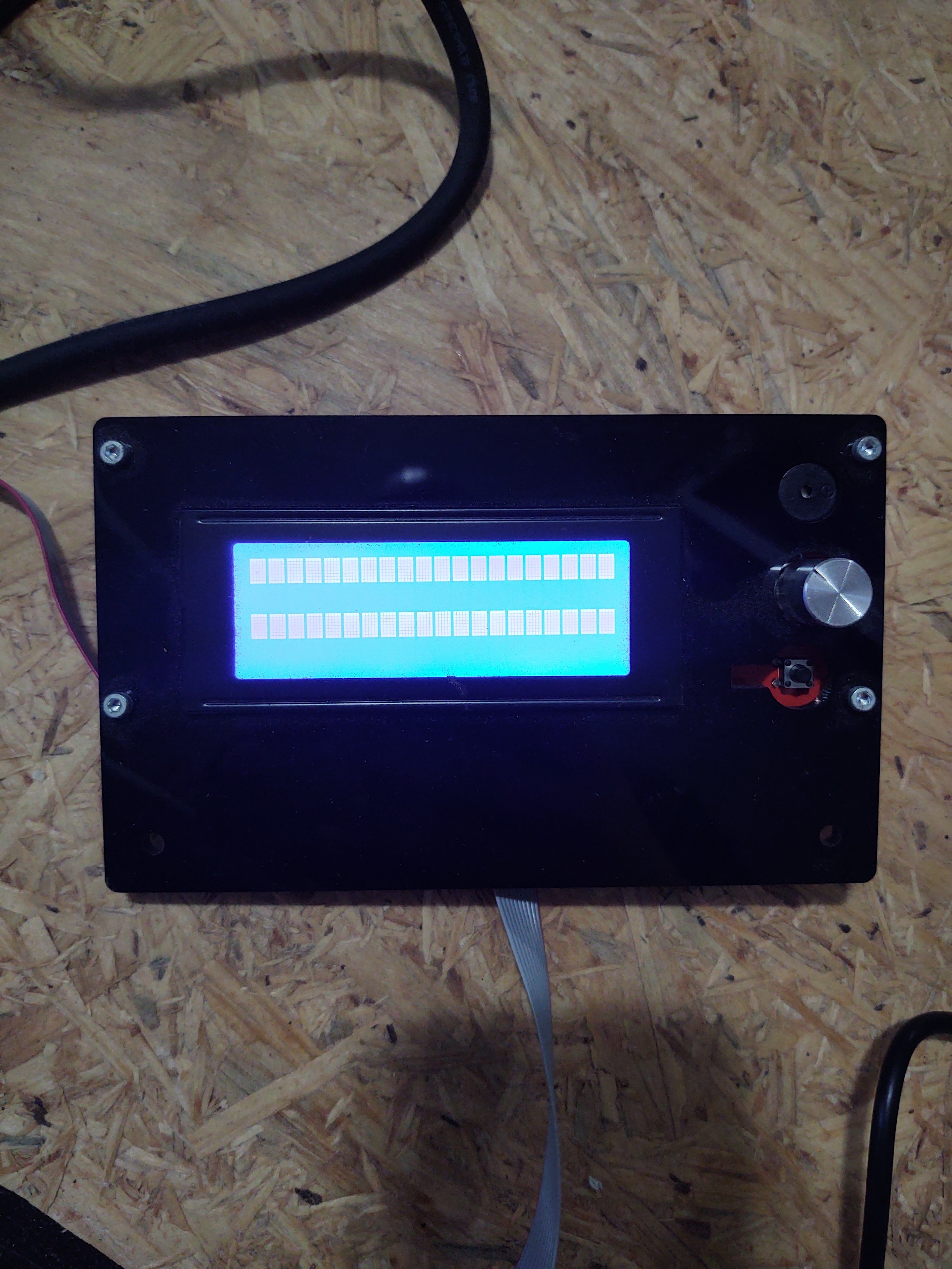
Honestly at this time I have tried so many different things I don’t really know if I have the standard build or the endstops. I am using the Marlin 2.0 I did not add anything in either of the configuration at all. Also in the tools board I have tried using Rambo and Arduino mega or mega 2560. Neither one of them work. At this time I would rather just start from scratch and I just need step by step procedure to get it started. I am completely new to this whole programing thing. I did attached a pic of my board and screen. What you can’t see in the screen is two rows of boxes on the screen.
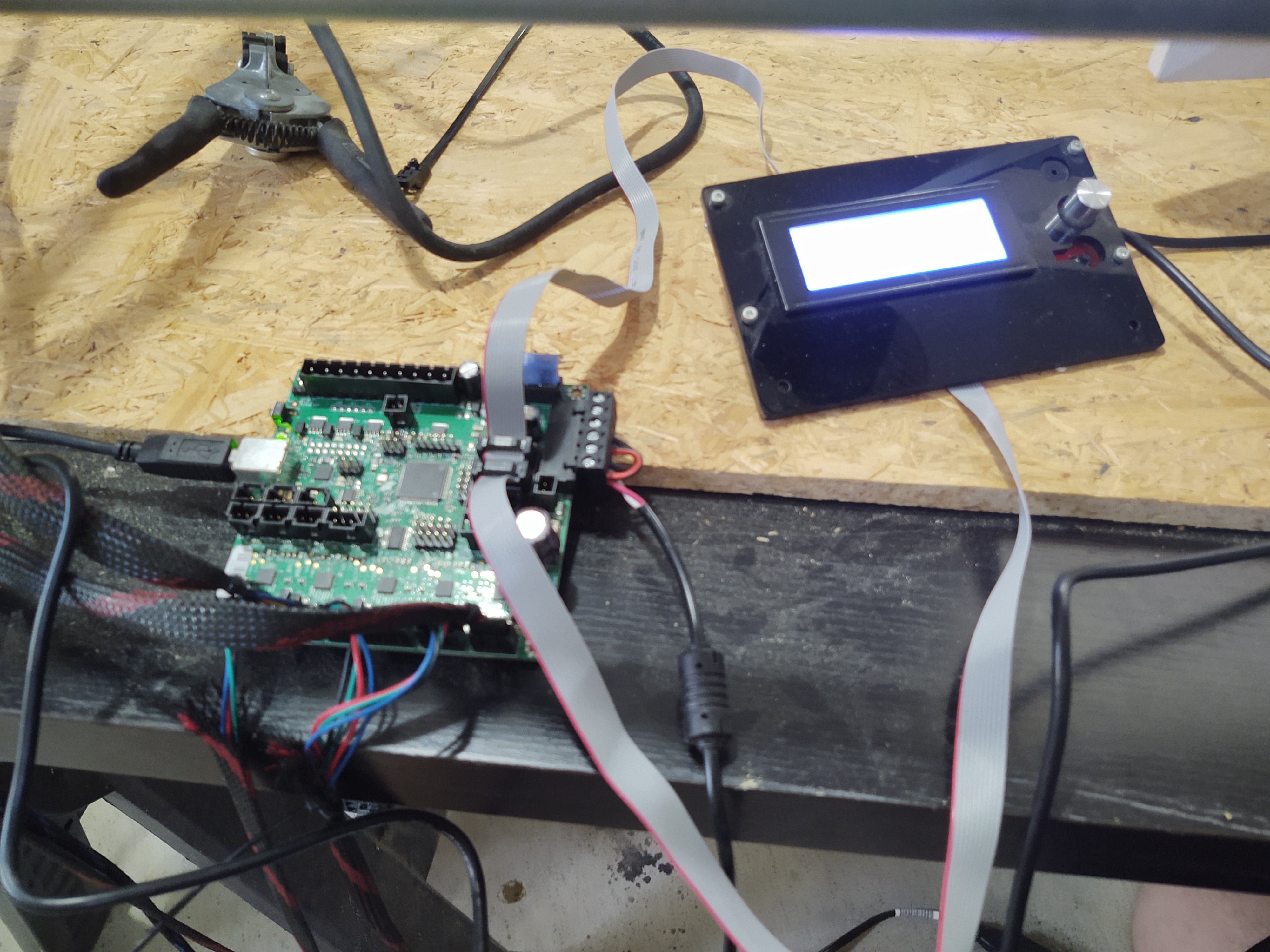
OK, it looks like you have a standard setup. Three drivers are connected, with the X and Y wired in series to power both motors. No endstops. I’m not as familiar with the LCDs, is that the graphical one, or the four-line character LCD?
My guess is that you’ll want https://github.com/Allted/Marlin/tree/V1CNC_Rambo, and follow the instructions at https://docs.v1engineering.com/electronics/marlin-firmware/.
The tricky part will be the LCD. If it is the four-line character display, you’ll need to make a couple of configuration changes in Marlin/Configuration.h.
You’ll need to comment out the custom bootscreen:
// Show the bitmap in Marlin/_Bootscreen.h on startup.
// #define SHOW_CUSTOM_BOOTSCREEN
Uncomment the correct LCD screen:
#define REPRAP_DISCOUNT_SMART_CONTROLLER
Comment out the full graphical screen:
// #define REPRAP_DISCOUNT_FULL_GRAPHIC_SMART_CONTROLLER
2 Likes
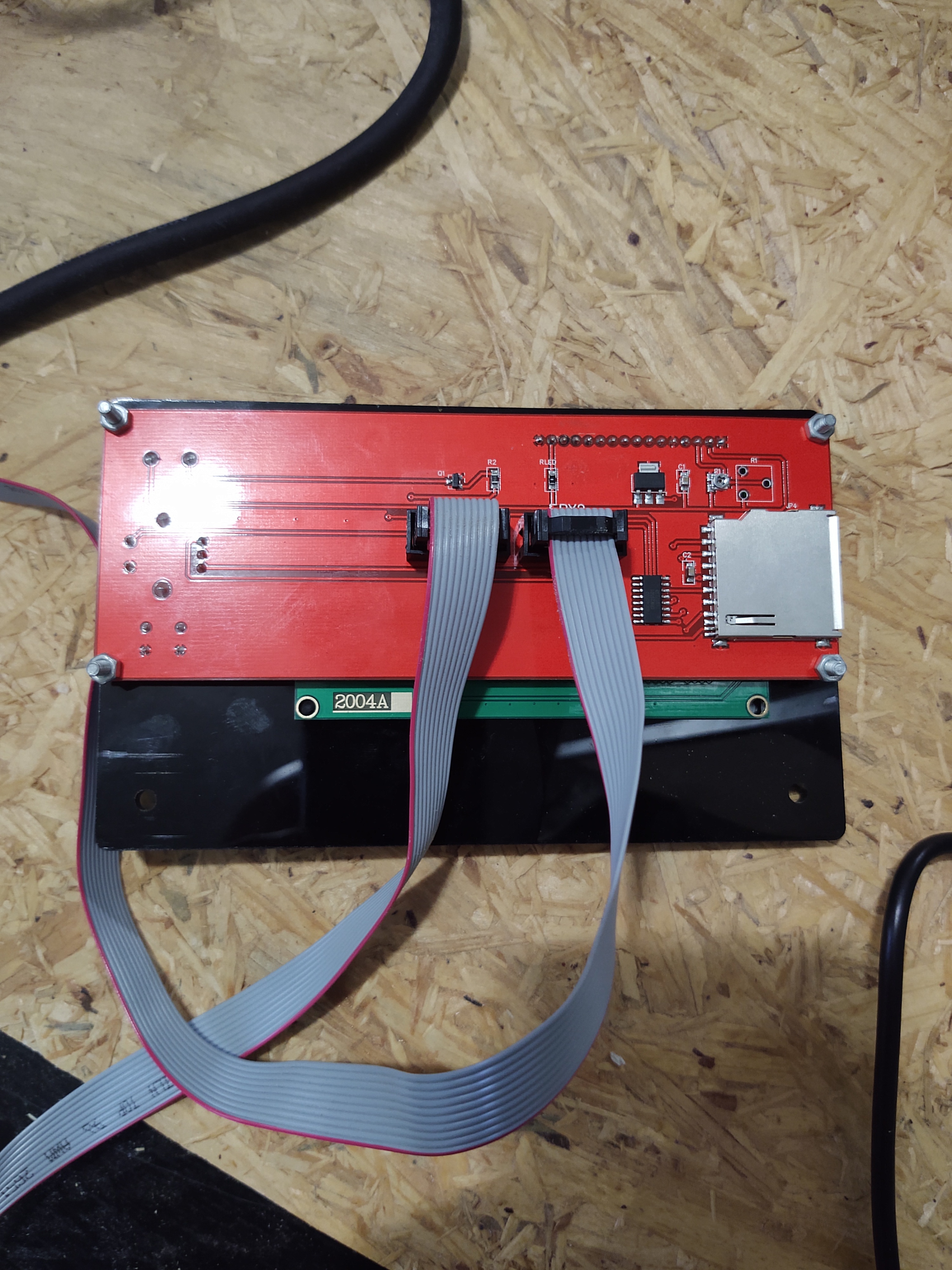
Yeah, that’s the four-line character display. I have one. See my edits above. The first change is right at the top of the configuration file, the others are further down. It’s easier to search for the names.
Oh, and all those config options are tempting and all that, but try to avoid them for now. Wait until you find you need something before you go looking at the extra bells and whistles… 
I am really new to this programming stuff. I don’t understand what you mean by comment out and uncomment.
If you could just show me what it looks like before and after that would really help me out thank you so much.
To “uncomment” you would change a line that looks like this:
// #define REPRAP_DISCOUNT_SMART_CONTROLLER
to:
#define REPRAP_DISCOUNT_SMART_CONTROLLER
Those slashes tell the compiler to ignore the rest of that line. To comment somthing out, you would do the opposite, you would add the slashes at the front.
If you have the exact same hardware as the “standard” build, flashing the rambo from arduino is pretty simple. So you could always just buy the right LCD screen, or just run “tethered” with a laptop running repetier host.
But that screen is a bit “off the beaten path”, so to get it to work, you’ll have to make some changes. Luckily, K is awesome, and he’s detailed exactly what lines to change for you.
Once you see what actually has to be done, you’ll see it isn’t too complicated.
Before:
// Show the bitmap in Marlin/_Bootscreen.h on startup.
#define SHOW_CUSTOM_BOOTSCREEN
After:
// Show the bitmap in Marlin/_Bootscreen.h on startup.
// #define SHOW_CUSTOM_BOOTSCREEN
Before:
// #define REPRAP_DISCOUNT_SMART_CONTROLLER
After:
#define REPRAP_DISCOUNT_SMART_CONTROLLER
Before:
#define REPRAP_DISCOUNT_FULL_GRAPHIC_SMART_CONTROLLER
After:
// #define REPRAP_DISCOUNT_FULL_GRAPHIC_SMART_CONTROLLER
2 Likes
My cnc machine works but my screen still looks the same.
The screen may have a knob to adjust the contrast.
If you look at my picture that I have displayed above there are two sets of boxes going all the way across the screen. Right now I can run the program on repetier host. I am also wonder if there is any other good programs out there that any one else use. Does anyone know any good program to transfer jpeg to gcod? I am just starting off with this whole programming stuff and need a lot of help to get this cnc machine running.
Take a took at the software workflow.
k cummins I got the board working and connected to my computer. My screen still looks the same do you know what setting I will have to change to get the screen to work?
For that, all I can suggest is flipping the connectors, and try it with the cables in the different positions. You can’t hurt the display (or the board), and one of the configurations is going to work.
I have flipped the connectors around and still all i get is screen off or the boxes all the way across the screen.
you mentioned this I am just trying to get clearer guidance on it is all.
Oh… Did you make the changes I detailed before? Those three before/after edits?
That should do it.
Well, that and rebuilding/reflashing it… 
Yes I made the changes it worked for a little bit. But the lcd screen still looks the same as the previous picture. I did get it to manually move a few times on repetier host then it stopped working. I have also got it connected to estlcam but I can not run it. Any solutions on any of those programs?