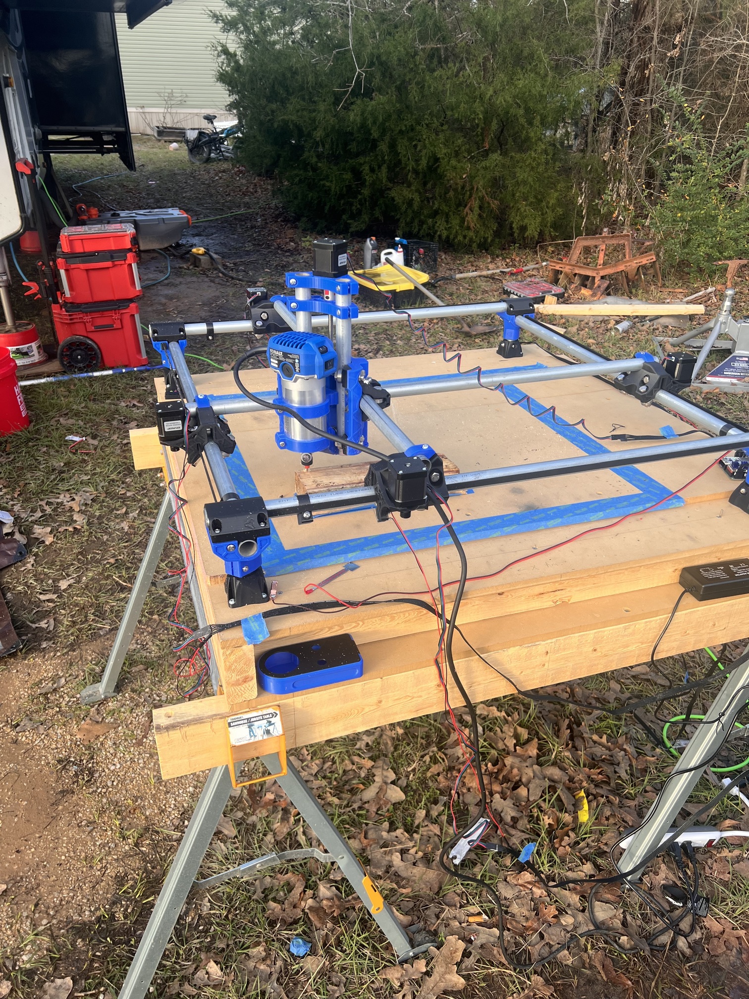
I’ve been pretty busy even though we’ve had nasty weather here in TX, with two crazy thunderstorms this week. Today was the day I finally got to make my first cuts since it dried up.
I know it isn’t the crown, but I used Fusion for CAD/CAM of two slots and a circle in HD foam. My main speed bump after getting my machine to move, was that I may have misunderstood something about the workflow/setup for the job as it pertains to setting G54 work offsets. Please feel free to correct me or provide advice/better ways.
Clear the table
Smoke and think about step 3, but then also check that all of the connections are good.
Secure workpiece to the table.
Check that the bit and router are secured.
Power up
Home XY using webui
Moved XYZ to right above the orgin of the workpiece (about x5y5z20)
Run probe for XYZ (I wrote my own and will post it here, please someone tell me why setting G54 X0Y0Z0 with the macro calling for G10 L2 P1 X0 Y0 Z0 (G54)would cause my machine to move outside of the stock area, but when I use the webui “zero all” button uses G10 L20 P0 (G53?) the machine then goes to the correct places?
Turn on router
Start job using the play button on the webui for the .nc file
Feel accomplished as one would after riding a bicycle with training wheels for the first time.
Finish job and turn off router.
Here’s some feel good videos of me being way too excited and messing up, but learning. Thank you to everyone who has helped and will help me in the future. Because I still have a lot to finish up before I can really get at it. I’ll be tidying up wires and putting the board into a case this week.
M0 (MSG attach probe for Z probing press to resume)
G54 G38.2 G91 Z-30 F200 P0.5; fast z probing with probe plate thickness 0.5mm
G0 Z3 F1000 ; lift z 3mm
G54 G38.2 G91 Z-10 F50 P0.5 ; slow z probing with probe plate thickness 0.5mm
G10 L20 P1 Z0; reset coordinates
G0 Z20 F1000 ; lift z up 10mm
G0 X-20 F5000; move x left 10mm
G0 Z-25 F200 ; lower z again
;X probing
M0 (MSG X PROBING move plate to left side and press to resume)
G54 G38.2 G91 X30 F200 ;fast probing
G0 X-10 F5000; move x away
G54 G38.2 G91 X10 F50 ;slow x probe
G10 L20 P1 X3.675 ;reset x coordinate (tool radius + probe x side thickness)
G0 X-10 F5000 ; move x for clearance
G0 Z20 F5000 ; lift z
G0 X12 F5000; move x back for y probing
G0 Y-20 F5000
G0 Z-20 F200
M0 (MSG Y PROBING move plate to front side and press to resume)
G54 G38.2 G91 Y20 F200 ; fast Y probing
G0 Y-10 ; move y away
G54 G38.2 G91 Y10 F50; slow probing
G10 L20 P1 Y-3.675 ; reset y coordinate (tool radius + y probe plate thickness)
G0 Y-10 F5000 ; move y away
G0 Z20 F5000 ; lift z
G90 ;absolute
G54 G0 X0 Y0 Z10 F5000 ; move to 10mm above G54 origin
I had trouble early on with g92 in PPs. Gotta remember that it’s there, and since it’s usually setting zeros, gotta make sure you move to the right zeroes first. I don’t always want the same zeroes, so I deleted them from the PPs I used. I think I only saw it in Marlin PPs. Haven’t had a problem with any of the GRBL PPs I’ve used.
I had assumed if I zeroed G54 by using G10 L2 P1 X0 Y0 Z0 that I’d be good. But the PP is using G92, and I didn’t find that until I saw the linked post/looked in the PP file. The way I figured it out at that moment was by using the “zero all” button on the WEBUI on Fluidnc. I’m still a beginner, but from what I’ve learned so far from HAAS G-Code, G54-59 are work offsets that are used for multiple parts/fixtures. I am now assuming G53 (using G92 to set) is the work offset that the machine starts up and uses until it’s told otherwise. But I’m still trying to figure this out because the fluidnc wiki isn’t descriptive enough about these offsets.
I don’t know anything haas-specific or fluidnc-specific, but you’re right about the workspaces g54-g59. Some systems (like grbl-hal) also add extra spaces like G59. 1-G59.3,etc).
G53 is the machine coordinates, and THAT is the space from which g54-g59 are offset.
G53 is defined by the homing operation, and you can’t change it (as far as I’m aware) any other way. This is really handy if, you know the location of a fixture. Home, something like “G53 X15 Y20 Z-2” takes you to it, then you can select your workspace and set it to zero. You can also use the G10 L2 Px, (L2 for offsetting from home, aka G53 coordinate space, L20 from the current position) like you’ve found, but I’m a little slow and like to see my router physically in the position I expect it to be in. Some interfaces (like iosender) let you key in the offsets directly.
G53 is also great if you want to mount a tool height setter…you can always locate it with the same command, something like G53 X1 Y25, then run the probe.
If you are attempting to do anything with multiple workspaces, you don’t want to use G92 for anything, since G92 applies the offset to ALL workspaces.
G10 is the correct way, and what the PP should really be using for setting offsets.
Also,
It’s good practice to get in the habit of using G10 L2 P0 X0 Y0 Z0 instead of P1, as P0 means the “Active” workspace.
It’s more portable, and less likely to cause problems in the future if you happen to be in a different active workspace than G54. Only use P1-P9 if you definitely mean a specific workspace, regardless of which one you are currently operating in.
Just wanted to add that bit of clarity in case you weren’t aware, and for future readers as well.
I’m not knowledgeable with how PPs work, but this one doesn’t mention G10 at all so I’m not able to fix the issue except by using G92 or the webgui “zero all” button until I can sort it out. I’m all ears if someone can walk me through how to edit the PP to use G10 like I should be
I’m using the flyfischer one, and I think what caused me to be confused was I had checked the G54 offset block in fusion and assumed it would use G54. The PP must not pass that on for some reason.
Reading the Linuxcnc docs (especially the offset section that was linked a few comments back) was the details I needed to understand how fluidnc handles them. Now I just need to get the PP and fusion to play along, or I will just use the zero all on the webgui before every job.
I know it’s preached a lot here to use ETSLCAM but I’m trying to learn these things in preparation for becoming a machinist/CAM programmer. I’m waiting on The VA (VOCREHAB) so I can go to school, but looks like I’ll have to wait until the summer or fall semester since it’s too close and I have a lot of steps left in the process before I start classes.
Bottom line, I need to keep learning fusion since it’s used in CAD/CAM a lot more around here, unless it’s a big contractor or manufacturer.
That’s only for getting people up and running, and for ease of use for people who just want the thing to cut. It has a much lower bar for entry than something like Fusion.
No one would fault you for wanting to learn something, regardless of the reason, but especially if that’s a skill that’s beneficial to you, career-wise.
Personally, I have not used Fusion for CAM so I’m not much help with that, except that the latest code is here if it helps…
Thank you for the reminder link to the beta fusion PP. I almost forgot to try and get that setup today. I was using the other ones and even tried the native grbl PP, but I wasn’t getting a dialog box to input any parameters or anything, and therefore my gcode was starting out cutting without selecting working plane, units, etc. after installing the one you just linked, I am getting the gcode I would expect and have input into the start and end sections with files.
Learning how PPs work might be advantageous for me later in a machining career, and if not I still know just a lil bit more than I did yesterday.
Now that I’ve spent some time looking through the FF-PP and have implemented it in fusion, I understand what was going wrong. The other PPs were geared towards doing all the work for the user with set parameters. @Flyfisher604 coded it with fillable fields and adding start/stop/toolchange filepaths. G92 was not set in the other PPs and this one calls it out as part of the start.gcode file. THIS IS THE WAY!!! This makes me feel at home coming from Klipper with START_PRINT macros and such being injected into the gcode.
And I feel like I just overcame a small hurdle that has been holding me back by digging through the PP today. I got some good workflow repetitions in, WOOT WOOT!
The tool library is shared here. WARNING: You are responsible for configuring cutting parameters of these tools in accordance with your use case/machine/stock material/spindle etc. I have basically measured their geometry and put in my own cutting data for soft wood.