Ordered 3D Chameleon kit (MK3?) couple months ago. Didn’t assemble partly because I wanted to await RMRRF updates/announcements.
Have clearer understanding now, so here we go…
Parts
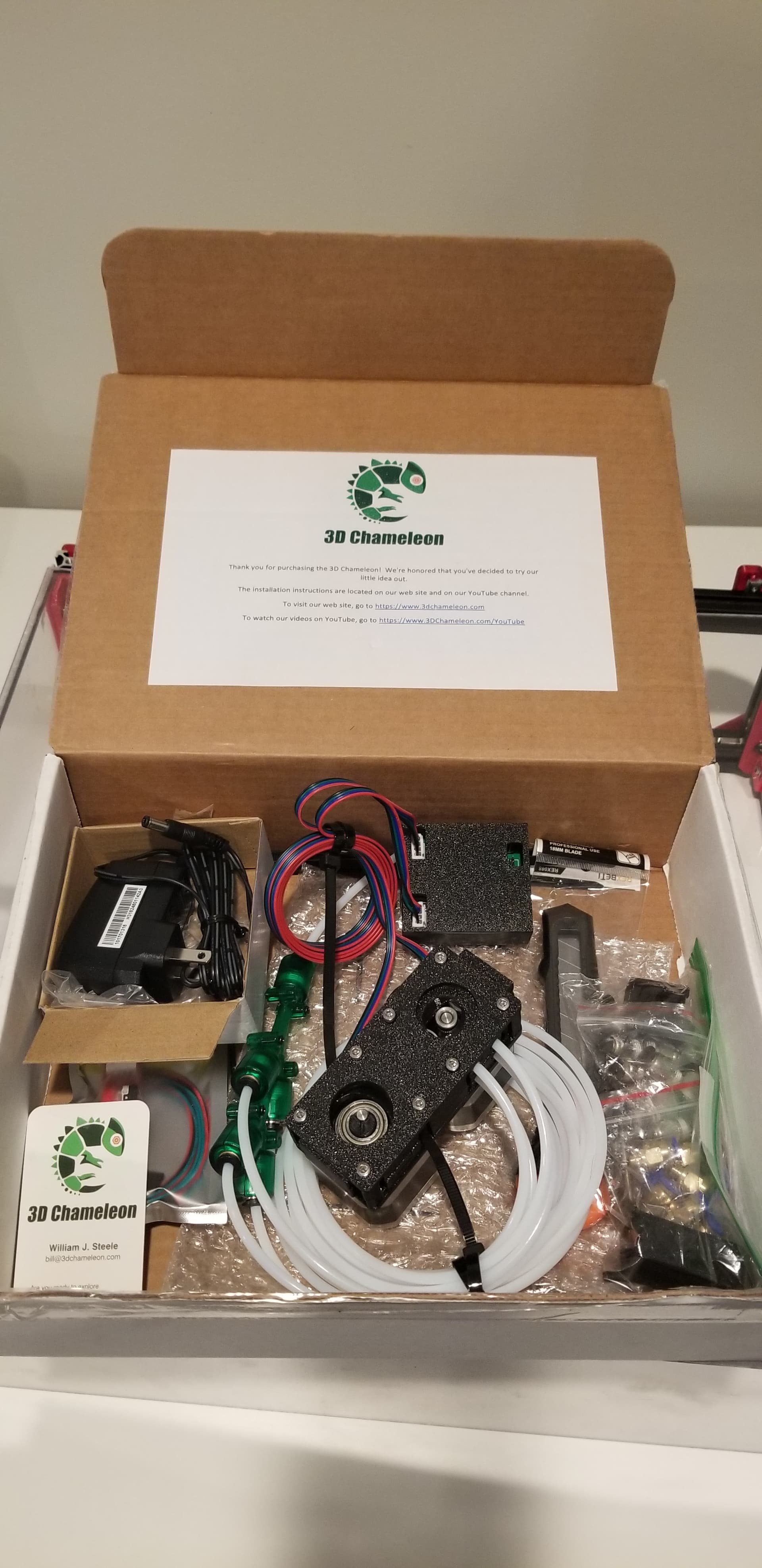
Below is the MK3 kit I ordered 2/5/2024. Contents of the current MK4 kits probably differs, but is nice to see Bill’s kit has many/all printed parts included, and preassembled…
Includes two steppers, the “Selector” (CAM moves sliding parts that engage/disengage bearing wheels to engage selected filament ) and the “Extruder”.
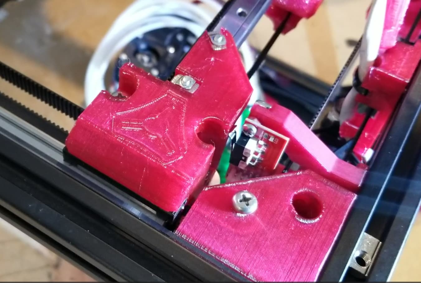
Ensure Switch is connected to 3DC mcu in correct orientation when plugged into the “Trigger” connector. “Green wire should be towards outside of the case, and red towards the center of the case” Bill.
DON’T worry if the 3.5 sec and 5.5 sec Selector switch commands that Bill demonstrates mismatch behavior for your 3DC. Newer video matches MK3/MK4 mode selection behavior.
Q: @ 16:30 Bill mentions 3DC isn’t compatible with filament runout sensors. However, am wondering if that’s still true, or whether Klipper macros can disable SFS (Smart Filament Sensors) during filament change/priming???
Chris shows how 3D Chameleon Selector/Extruder mechanism works by assembling one. Note that kits come Pre-Assembled. Watching this video helps understand how the mechanism works, and will better help answer WTF is wrong when it doesn’t work.
So looking at the open box photo, it is using 2 motors for 4 colors. I don’t recall seeing how the extruder transmission switches colors with the second stepper and I’m curious how that works. Can you describe it?
Yeah, one of the steppers has an offset cam that moves a sliding plate that pushes/pulls bearing wheels to engage the desired filament against an extruder gear on the 2nd stepper. The other stepper extrudes/retracts whatever’s currently engaged. Not sure if/how this’ll work with TPU/flexibles, we’ll see…
Best explanation I’ve stumbled onto so far is Chris Riley’s. Chris walks through assembly of the cam/gear, but my kit came assembled already. I just have to hook up, configure macros and tune I guess. Am following his recent series…
Curious if anyone’s found guides that worked out easier for them to get up an running?
I liked his Chameleon series. I’ll be rewatching since it’s been a while. Doubt much is missing other than things specifically needed to mount to my MP3DP v4. Will make notes and share info as I make progress…
This multiplexing feeding extruder gear just feeds to your direct drive extruder by pushing filament through the y tubes and into the reverse Bowden tube connected to the direct drive extruder on the hot end. It doesn’t serve as a Bowden extruder, so I would think it should work just fine for soft filament.
Does it actively feed during printing or just during the initial swap and purge?
Klipper users can optionally avoid needing the switch, and instead use macros, this involves wiring up (e.g. endstop GPIO + common ground) from the Controller board to the 3DC mcu. This approach will help speed up filament changes after the next 3DC firmware is released. All that said… Wiring up the switch is how most people seem to be setting up, plus having the physical switch makes diagnosing/troublshooting easier. My plan is to reduce variables, get slither of end to end functionality working, then optimize from there. Assuming some other shiney project hasn’t taken priority by then.
Parts
2x M3 x 10mm button head bolt
2x M3 Hex nuts
2x M3 T-Slot nuts
1x M3 roll-in half moon T-Slot nut
1x M3 x 8mm button head bolt
Skinny hex/philips drivers
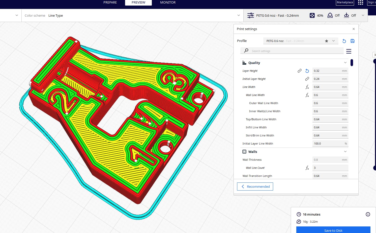
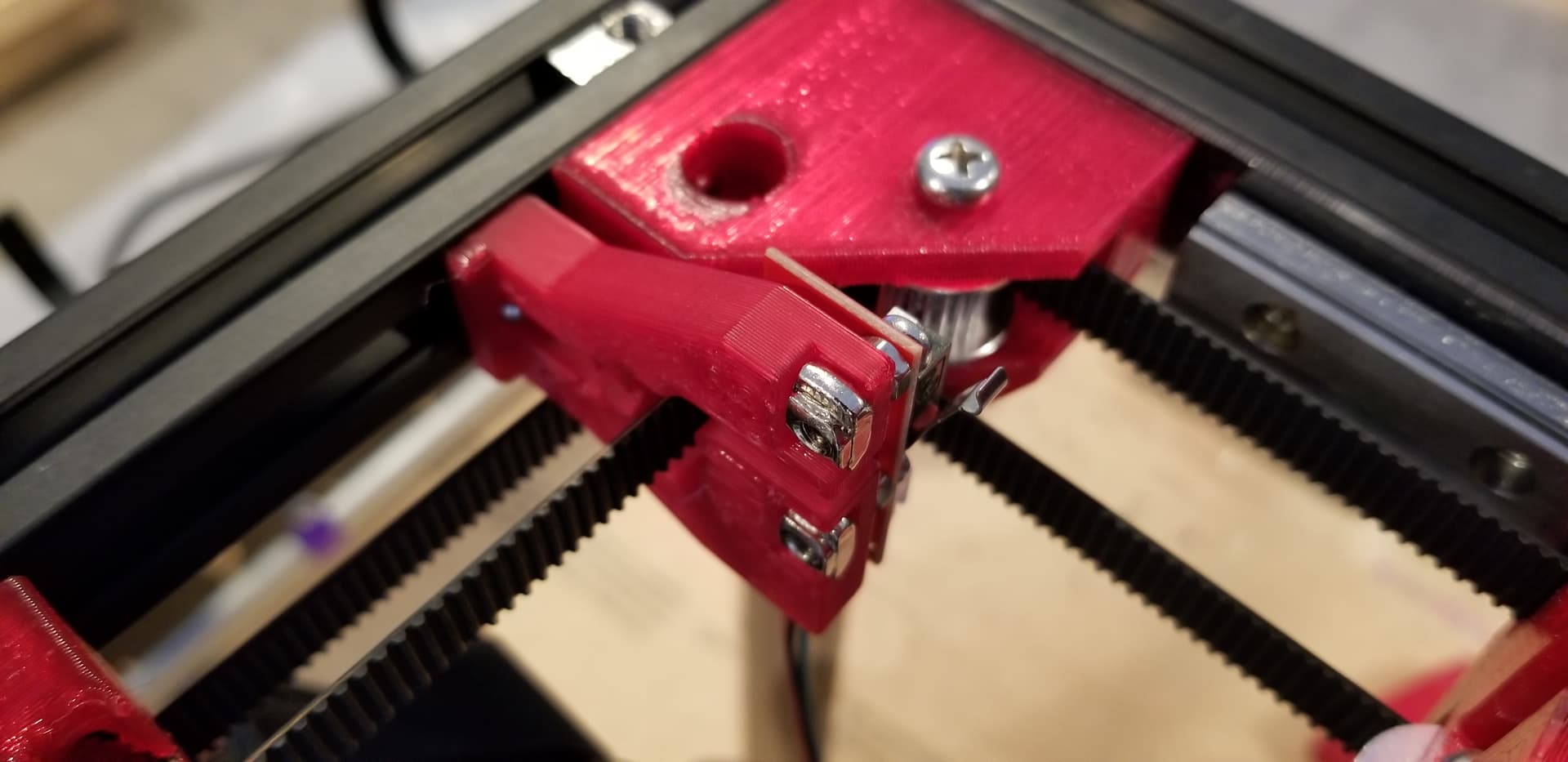
Assemble by threading belt through the printed part’s open slot. Fasten bolts in numbered sequence. 3DC switch has thru hole components, so use the hex nuts as a spacer between the 3DC PCB and printed mount. After snugging up bolts, verify microswitch triggers within 1-2mm Y Max. If extra arm reach is needed, then, carefully bend microswitch arm so arm lands on right gantry truck.
Check your wiring/umbilical expected range of motion is unaffected and nothing gets snagged/blocked. Personally Needed to ziptie and tidy up the loose wiring for my X endstop to avoid snag on the 3DC switch mount.
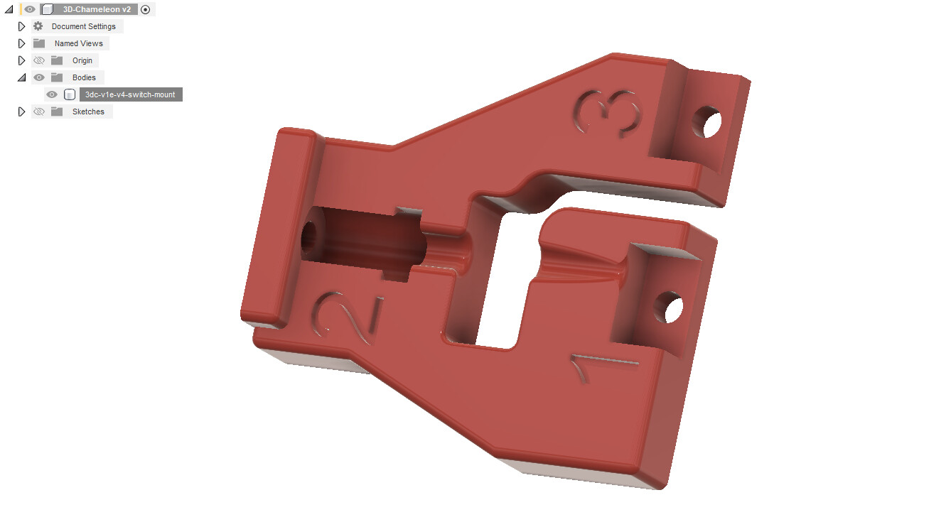
Nice that the kit was pre-assembled, no need to print anything except for the 3DC Switch mount. Nice that there’s not too many parts. However, although filament cutter 3D Clippy is ‘optional’, it seems like a very useful should-have, or must-have feature even. Still digging through the 3DC forum…
You have it running yet @azab2c ? at the rate its taking me to get all these parts printed for the ERCF it might be another month before I see a multi color part LOL
Nope. Switched to some other project(s) for a bit…
Partly because am waiting for Bill to post details/designs for the updated 3D Clippy and associated firmware. Thinking filament clipper will help reliability. Am refreshing https://www.3dchameleon.com/forum?feedType=all-posts more than a reasonable person should.
Also, I need to fix how filament feeds through the 3mm ID 4mm OD PTFE tube, to the PTFE pneumatic fitting, to the BIQU V2 H2S Revo. During filament load (unrelated to MMU or 3D Chameleon), am often seeing curled filament find a way to get wedged/stuck.
Have been using 3mm ID instead of 2mm ID to reduce filament resistance (seems like something some Voron folks do). However, although filament slides through PTFE very easily, the end of that wider 3mm ID results in filament hitting a ledge/restriction in the PTFE fitting. Ideally the PTFE fitting’s ID would be tapered. Am looking at alternative PTFE fittings and/or use drill press to taper fitting’s internals and/or switch to 2mm ID PTFE and/or something else(s)?
Even if I change/mod the PTFE fitting, am finding that the filament switch lever often needs flipping during loading. This also seems related to openings/internals not chamfered/tapered. So, am wondering whether the Chameleon’s extruder can ram past these obstructions, we’ll see…
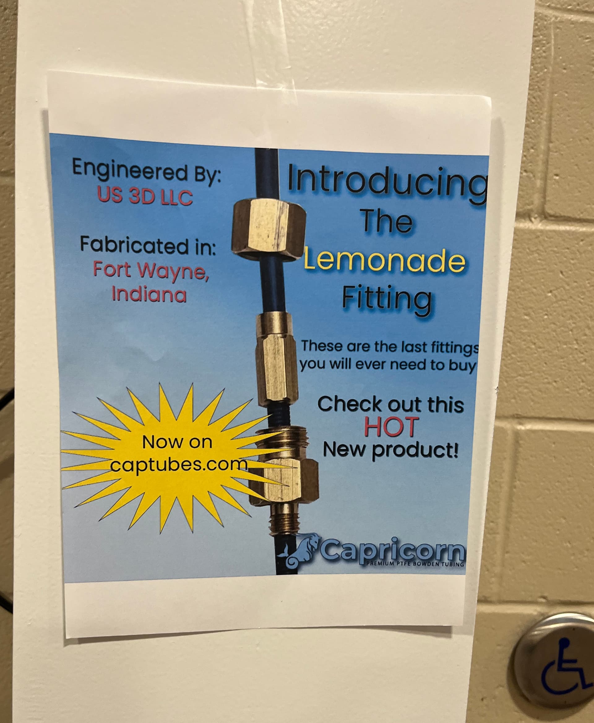
He was walking around showing his unique solution for bowden tube connections.
I didn’t quite grok the need/use case he was describing- but his fittings were very interesting.
Edit: his description of the use case sounds exactly like what you’re trying to solve.
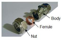
I see what he’s going for here … Basically, he’s taking a compression fitting, like what’s used in water hoses in your home (how a pipe is cut and a shutoff valve is inserted, for example)
and modifying it to fit PTFE tubes and screw into your extruder/hot end in place of the rather finicky PTFE connector, although it seems the middle piece screws onto the tube (as evidenced by the marks on the tube below but not above the middle piece) instead of sliding on and being “crushed” by the top nut to grab the tube. I’m not entirely sure it would help the issue at hand… the tube would still have to go all the way through the fitting that’s screwed into the hot end (it’s not connecting two different pieces of tube, it’s one piece all the way through), which would be equally as possible to do with a standard claw-style fitting (if it’s the right size, anyway). You would just never have to worry about it pulling itself back out ever again, like you might with the claw-style fitting.
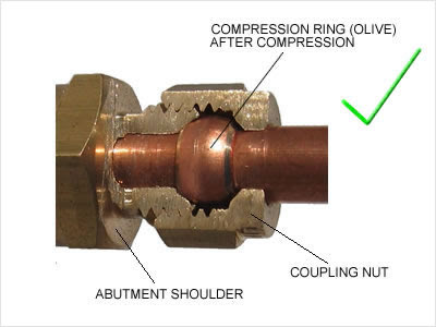
Because I’m new, I was only allowed to add one picture (understandable, they don’t want people spamming the forums). So here’s the second picture I wanted to add, the part about the ferrule being “crushed”:

")