Thanks for starting the baseplate/bed questions. Agree, will be helpful to know what sizes and parts people are going with.
Yep. Yep, mostly stock (e.g. Undecided on hotend). You’re welcome.
Thanks for starting the baseplate/bed questions. Agree, will be helpful to know what sizes and parts people are going with.
Yep. Yep, mostly stock (e.g. Undecided on hotend). You’re welcome.
All my beds are a bit different but they all print at 200x200. 214 is the average OD of my beds.
The original intent was to use one of the 214X214 (200X200 usable area) jist like Ryan designed, but I could only find (with reasonable shipping) 235X235 build platforms supposed to be 225X225 usable. Last minute, after sizing for everything else I did find a 214X214 platform and I’m using that. (No need of larger since my first repeat is 300X300.)
Thats what mine came out to. And the 120v heater works awesome
I’m struggling with this.
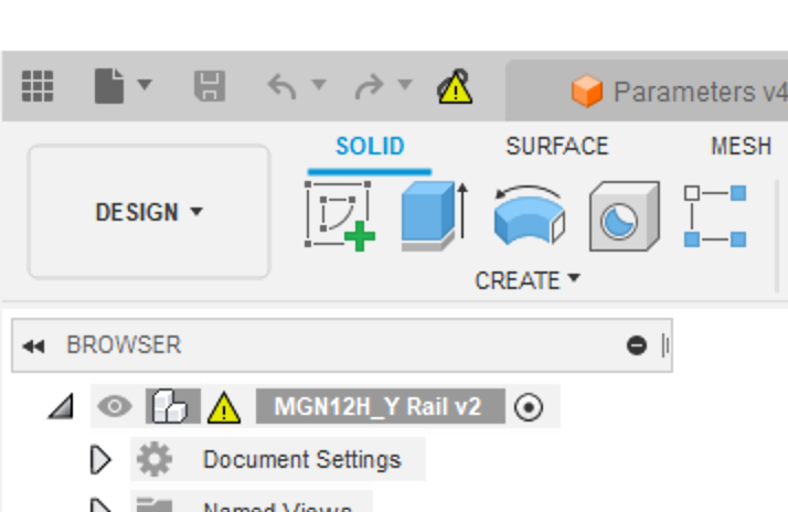
On the “CAD Files” link, I selected “open in Fusion 360” — and it added them to my cloud area under Admin. I got a whole list of files. I opened the Parameters file, and edited the three main params as according to the documentation (red arrows). I then opened the main file, saved a copy of it, closed it, reopened it, and the MGN linear rails are still too short. I also had to edit the sketch with the V1E logo to move it down and to the right, to get the logo cut in the front panel to be usable. Any idea what I did wrong?
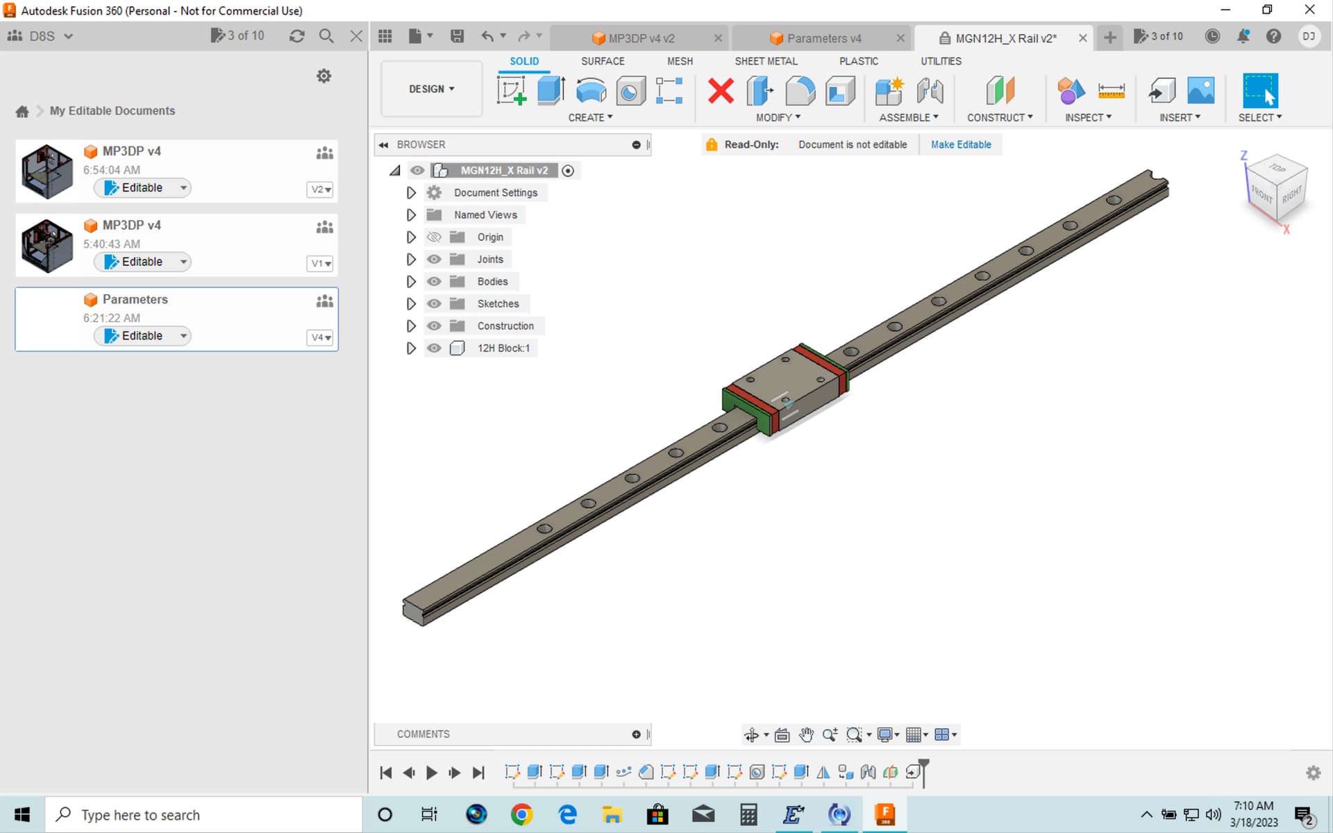
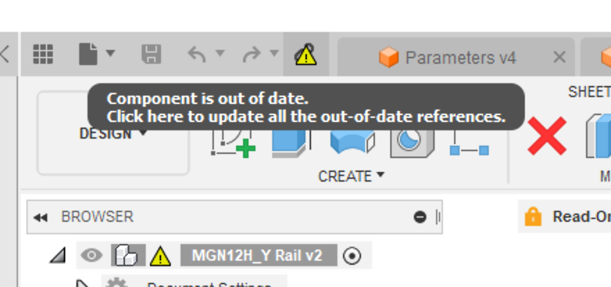
After reading again, it occurred to me that I might need to also “open” the MGN rail files in the list, and so I tried that, first with X. When I opened it, it said the component was out of date, and it allowed me to update it. However when it updated, it did not move the screw hole locations properly. See pic:
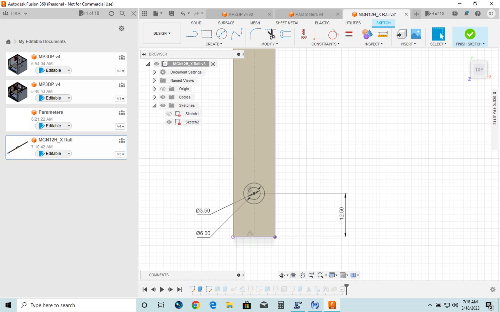
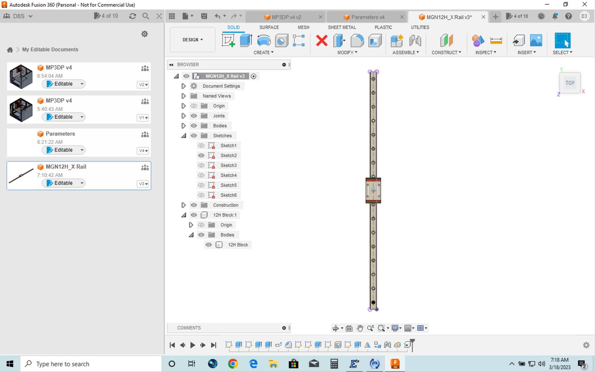
I located the sketch that corresponds to the first hole’s placement, and I added a dimension to constrain its distance from the end of the [newly resized] rail, and (by assuming it should be half of the 25mm increment), I assigned it to be 12.5mm, and then when I save the sketch, the holes in the resulting linear rail seem to be right.
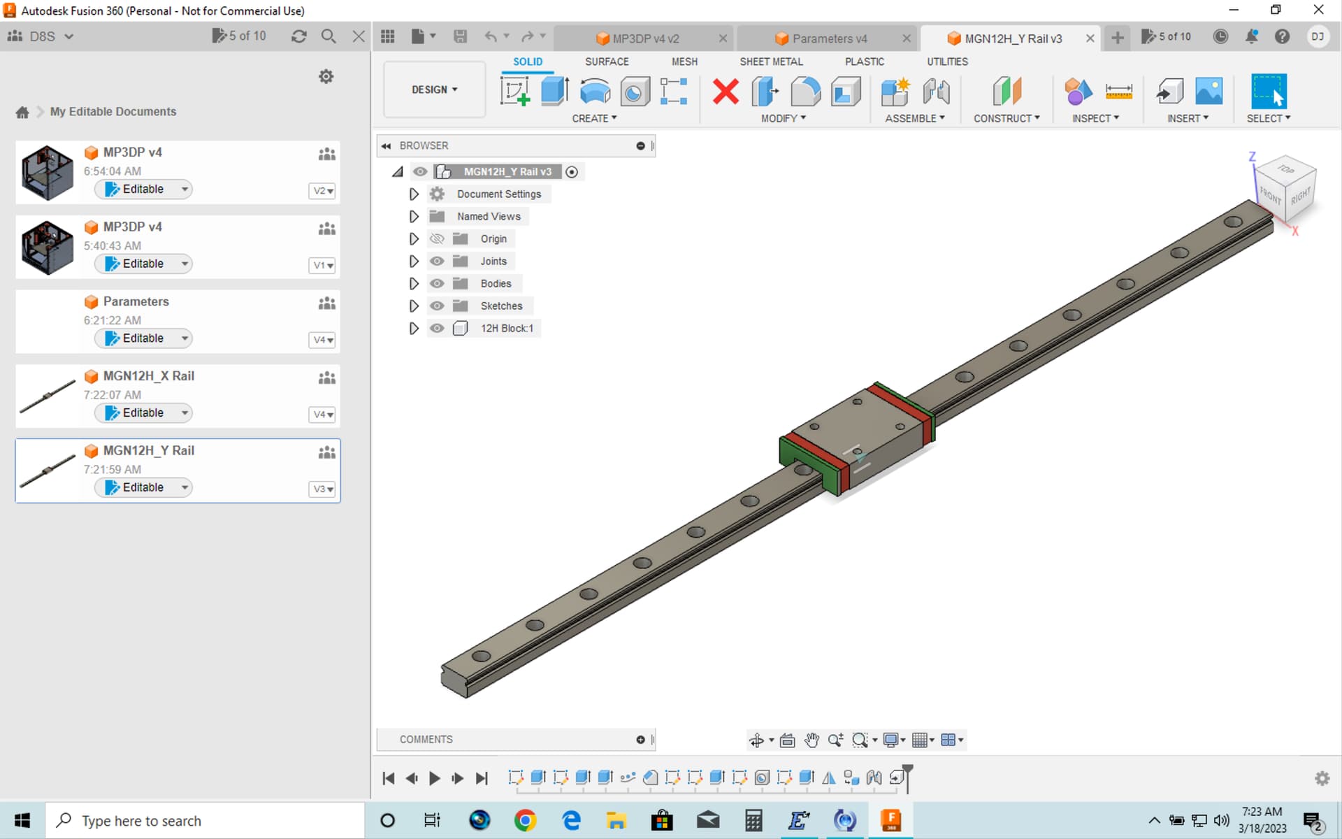
Afterward I repeated the same “open > update the out of date component” approach on the Y rail, and its holes did not need fixing.
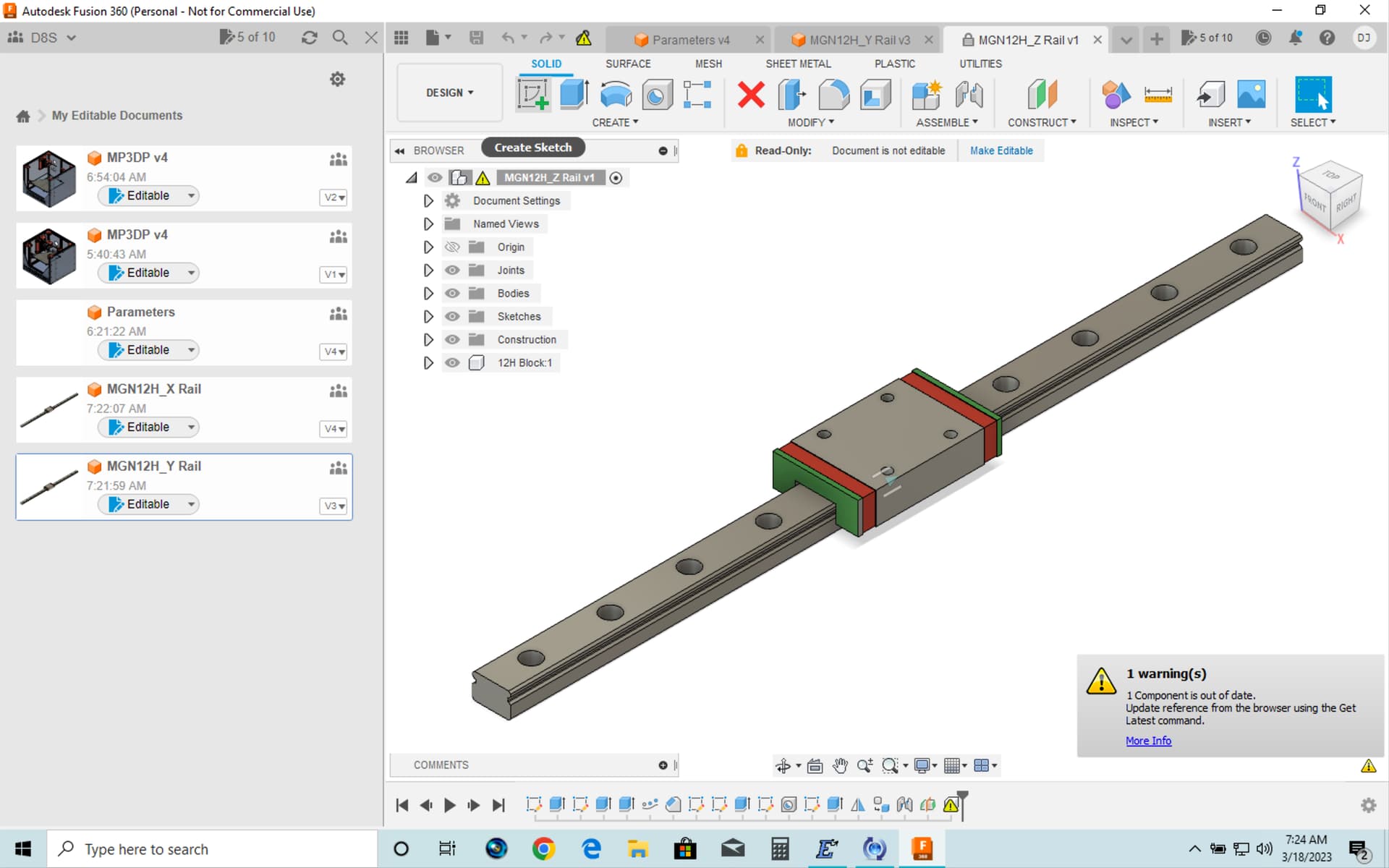
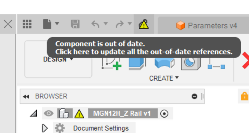
Similarly, when I updated the Z linear rail, it also did not need its holes fixed:
I thought I fixed that one. I have no idea why it is being a pain. I will dot it again. Really though, the holes are just cosmetic and nothing is based on them.
Got it.
I’m also getting another glitch, this time on trying to resize the bed size for the “bed support” part.
The bed size / sketch does indeed open at the size that is based on the edited params. However, my bed is 310 x 310, and my params edit was 325 x 325 because of 25mm increment. So it comes in actually 15 mm too much in X and Y.
So, I edit “Sketch1” and then I double click on the Dimensions for X and Y, and change X from “MainWidth_Ref” to “MainWidth_Ref - 15 mm” and change Y from “MainDepth_Ref” to “MainDepth_Ref - 15 mm” — which works as expected.
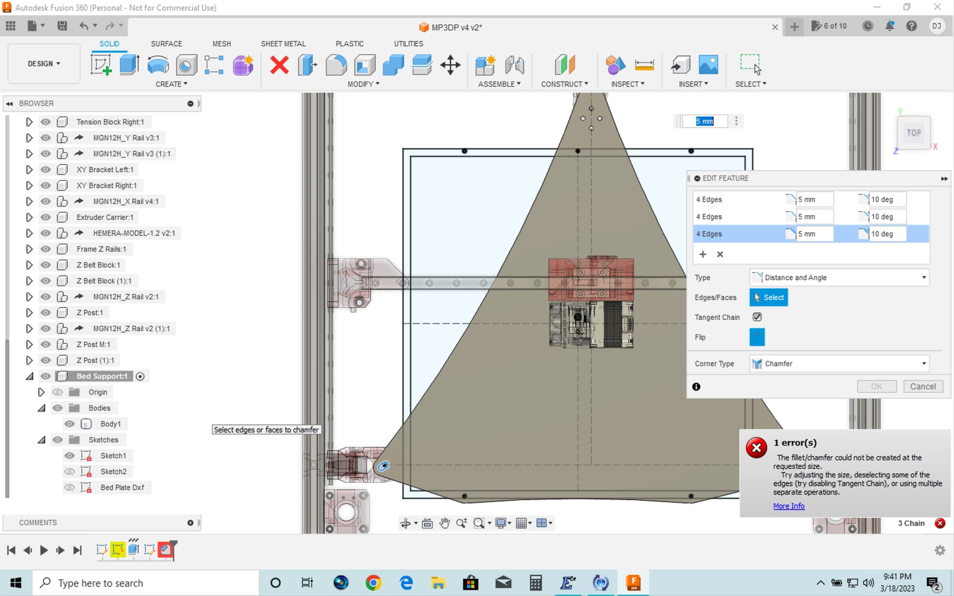
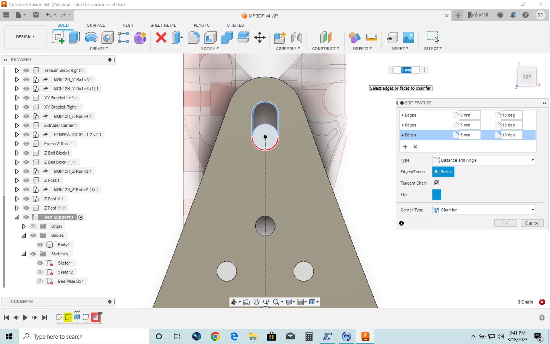
However, I then get an error message that a chamfer cannot be done. See first screen shot. I was able to scan around and see the red outlining hint on the offending chamfer edge — at the back of the bed support part. See second screen shot.
I happened to still have a prior copy of the main component with all the parts, and that has not had the bed size sketch1 edited, i.e. is still at the 325x325 as shown in the updated params, and it shows the timeline entry for the chamfer in red also, and gives the same error. So, this chamfer failure seems to be unrelated to / not caused by the dimension edits described above.
I also tried to compare the “bed support part” in your latest published CAD files and it does not look like a chamfer has been successfully added to the part. ?
You have a bed with a 310 by 310 usable area? If that is the case, yes round down. There has to be limits, not every single item will work. I can add that to the instructions, I just never imagined a bed outside of a usable 25mm multiple existed.
The chamfer is a 10 degree on the bed bolt slot to allow for tilt to the z mount. As far as I know the current version has no errors, the physical part gets modified by hand after cnc since it is such a slight adjustment. If you are worried about it just delete or ignore it. It is there for extreme bed tilt (non planar printing, which I doubt anyone uses).
I think the bed is 310 x310 actual size, with an “intended” usable area of 300x300. So, I guess rounding down to 300 (instead of rounding up to 325) is an option. ?? If so I will do that as it would save a bit of size on a lot of things. Maybe I was mistakenly thinking I had to input /go off my actual bed size instead of the slightly smaller area intended as usable?
Got it. Thanks!
I edited the timeline entry for the chamfer, and changed its depth from 5mm (at 10 degrees) to 4.5mm (at 10 degrees) and then it computed with no error. Until then, I was not seeing any chamfer as the entry was simply not being computed due to the error.
Correct. If you look at the bed sketch you will see where you can put in the actual size, and actual hole placement. Usable dims go in step one.
Doug is asking all the questions I should have before I cut my bed lol. Had I known all of this I wouldn’t have a 10mm strip of aluminum all the way around lol. Oh well. Ill get it right on the next one
Hope springs eternal!! You’re still trying to get the first one working and already thinking of the next one!!
Seriously addicted ![]()
I should talk, I can’t decide which machine to build next.
Mike
Yes its an issue…that I have no plans to fix lol. I’m trying to get this one working so I can print the parts for my wife’s ZenXY table. the kit from Ryan is supposed to get here today lol. I just know me and when he comes out with a V5 or whatever it will be called ill want to build that too lol. I’m learning so much from this build that I truly hope the next one will go MUCH smoother lol.
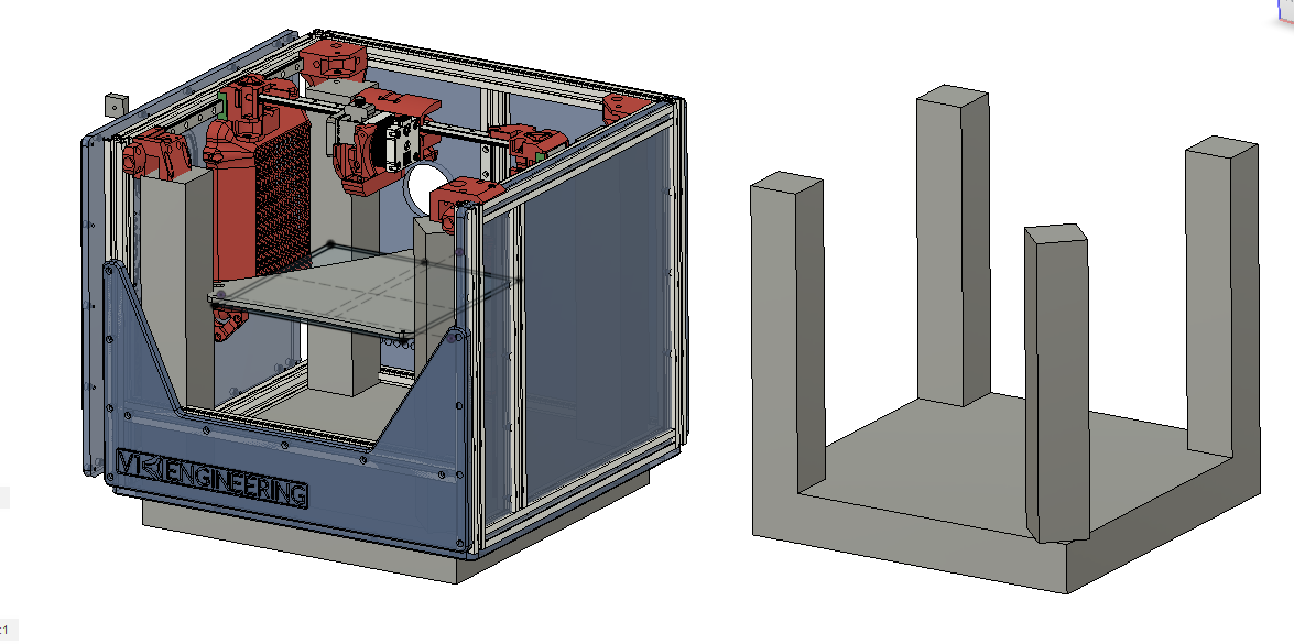
Someone here already seen/made a LACKing no-extrusion Printer? Looks like extrusion free was an option for Repeat v1. Making the v4 design fit a LACK like this Hack a Day would be funny. However, feels like it’d be more hassle than it’s worth.
Taking a quick look at the larger LACK table. But, will be building a mostly stock extrusion frame, will hopefully be faster for me follow what others have built already. Can always Mod later after reaching a working state first.
Will oversize the Frame Corner Posts height (like MP3DP v3 / Repeat v1) so a flat surface can be mounted on top. Mainly for heat and finger retention.
Have seen crazier ideas… Milk Crate 3D Printers…
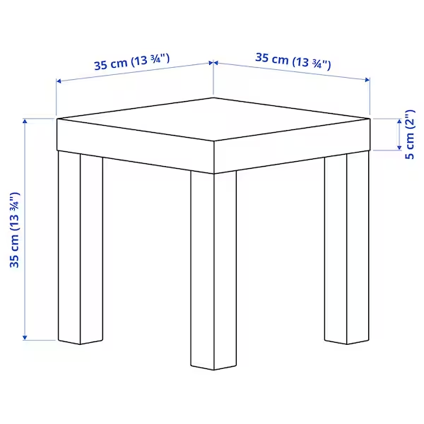
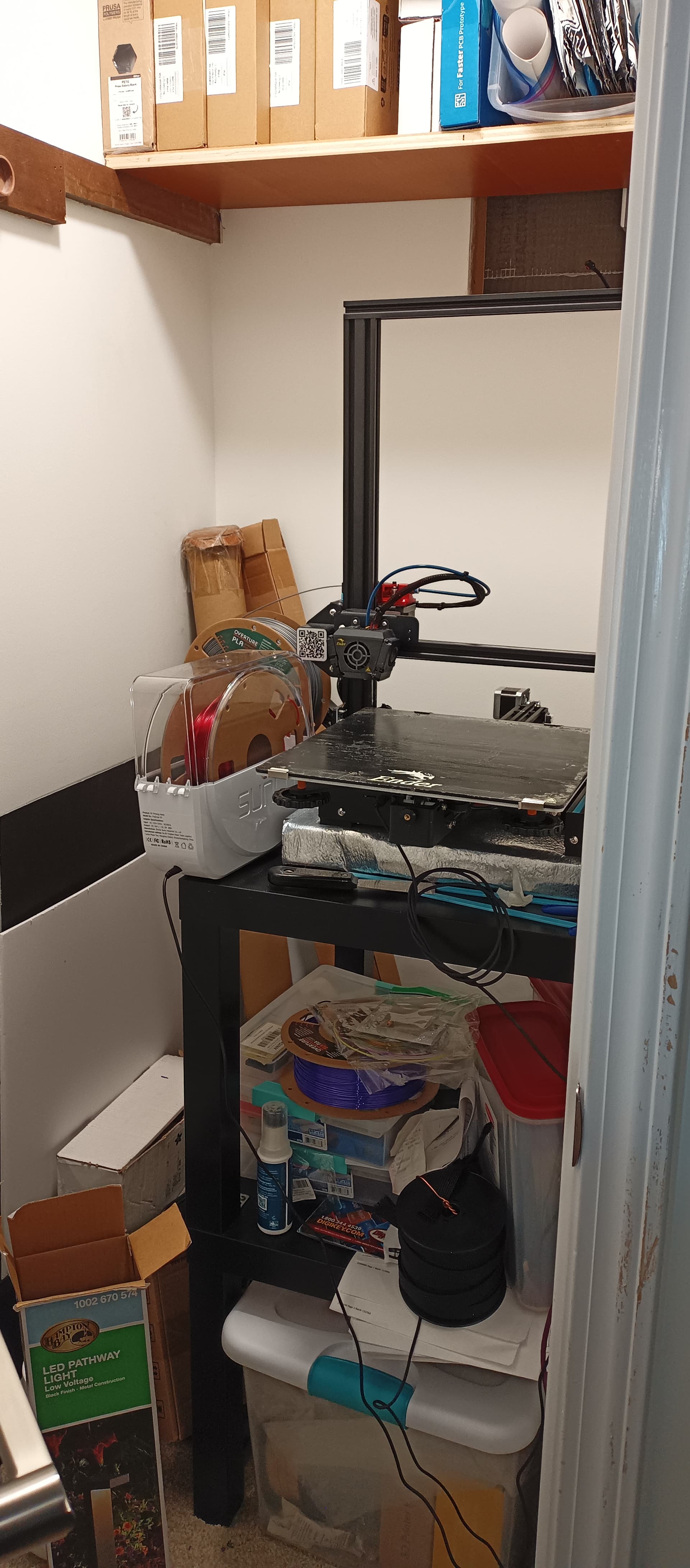
Mine is sitting atop one of those LACK tables right now. The 250mm square build won’t fit inside one, but the 200mm square build would easily.
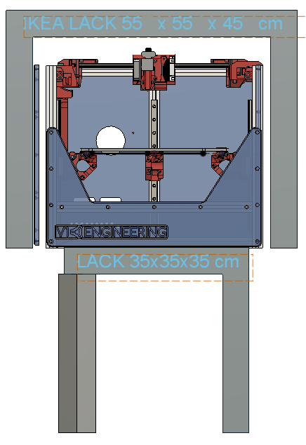
Cheers Dan, have a couple of the larger 55x55x45cm LACKs too.
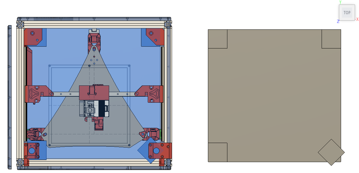
Relative to the two LACK sizes I can see, a 200mm^3 usable would look like…
Will either make it fit inside a LACK, or have the same/close foot print as a LACK to make stacking/integrating into my existing setup easier.
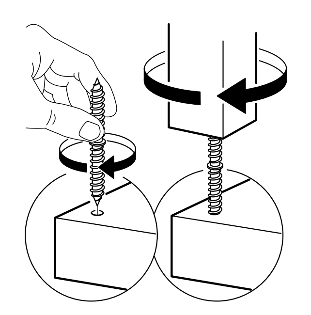
The one twisted leg is perfect. I have one in my kids room and it has one stripped leg. It is only a matter of time before it collapses.
You can do this one without extrusions if you would like, The only part I would change is the Right XY stepper, I have it curl over the top of the extrusion, that would work on a piece of wood as well but you could just as easily make it flat to fit in a box. For me extrusion gives me a bit of wiggle room and seems more seasonally stable. My box only printers were not perfect enough for me and changed from season to season (32F-110F).
![]() , Yeah, was experimenting/wondering if twisting front legs 45deg would enable fitting a modified swiss Z stepper mount. Slightly unhinged 45deg angles would be more V1E like too.
, Yeah, was experimenting/wondering if twisting front legs 45deg would enable fitting a modified swiss Z stepper mount. Slightly unhinged 45deg angles would be more V1E like too.