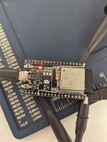
broken (jackpot board) or Broken ESP 32 board?
Can’t say without more troubleshooting.
thanks for sticking with me on this!
We’ll figure this out.
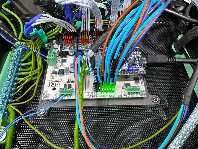
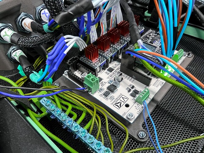
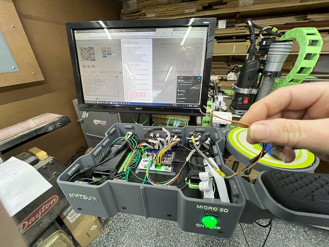
Scanning your thread, I see lots of pictures of your awesome build but no close-up pictures of the as-installed Jackpot and wiring. We may need some more pictures.
on some boot-ups the gpio 2 green light comes on and on others the gpio 2 light is off
What are the differences in $SS output between when GPIO 2 comes on and when it doesn’t?
Did you define something in your config.yaml for that MOSFET?
Pictures of your wired board would really help troubleshooting.
no i did not define anythin in config.yaml for gpio2
i plan to use gpio 16 for a tool length sensor but debugging this has prvented me from getting to testing the tool length sensor or changing the yaml file to add it at all
all of the stepper wiring and proximity wiring is using shielded cable and the drain wires are grounded to the ground buss in te controller as you see (green wires)
Wow, I haven’t seen a white Jackpot in a while. Did you buy your Jackpot a long time ago?
My recommendations for troubleshooting-
Cap/stow the wiring for your tool length sesnor and power up with that removed. Any change?
If that doesn’t fix things, we may need to add a pull-up resistor either to your ESP-32 or to the jakpot board itself.
For @vicious1 - were any white Jackpot boards made that didn’t need a pull-up resistor on the ESP-32?
wonder if a factory reset of the esp32 board might shake things up?
Nope.
If you need the pullup resistor you need the pullup resistor.
I’d still try with your sensor wires stowed.
well if you consider 4 years ago a long time then yes I bought it a long time ago. My build plans got put on hold because life got in the way.
I guess getting a pull up resistor would be cheaper than getting a new jackpot board. I’ve been looking at other GRBL compatible boards too but I’m willing to keep trying with the Jackpot It was working so I know its possible.
You have an early jackpot.
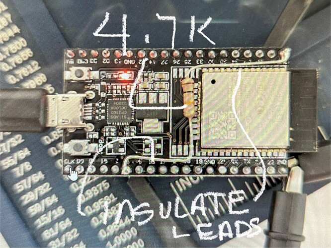
From an earlier thread, you need to install a 4.7K pullup resistor as shown below (Insulate the leads, this is actually a scary picture!). Any value from 1K up to 4.7K will fix it.
The other thing I see in your build is you have wiring in close proximity to the ESP-32 WiFi antenna. That’s a no-no as well. Move all the wiring to stay well clear of the antenna. Imagine a 3" pvc pipe centered on that anteanna and going straight up and out of the enclosure. That’s your stay out zone for wiring.
I’d recommend adding the resistor to the Jackpot itself. Then you don’t have to worry about it if you later change the ESP32.
Also, if your current ESP32 is the same one that came with the Jackpot, you shouldn’t need it. I didn’t run into this issue until I changed my ESP32.
To answer a previous question disconnecting the Tool Length sensor wires from gpio 16 and vmot on the mosfet did not make the driver error go away
The 4.7 k resistor I get but are the leads you are wanting insulated the wires exiting both sides of the resitor as I have marked here?
just to be clear is this “issue” corrected on newer jackpot boards? I will review threads here on the forum to educate myself but since we are here I thought i would ask.
yes the esp32 came with the jackpot 4 years ago
Exactly right. I stripped the jacket off of some 22 AWG teflon jacketed wire when I did mine.
Not true. I helped troubleshoot this problem and participated in the tests that eventually changed the jackpot board design to include that resistor.
True, if one wants to disassemble everything then putting the resistor on the back side of the board is more like the later jackpots where the resistor is built in.
Pay careful attention to the pin layout if you do this.
Yes. Here is the changelog. The 1.2 rev adds the resistor to the Jackpot.
with the other revisions listed on the current Jackpot would it make sense to just order a new jackpot for reliability and peace of mind IE: if you were in my shoes would you add the resistor to an old board or just get a new one?
