Before “zeroing” just ignore what the Z reads in motion control area.
What matters is that you get it zeroed on top your work piece.
Before “zeroing” just ignore what the Z reads in motion control area.
What matters is that you get it zeroed on top your work piece.
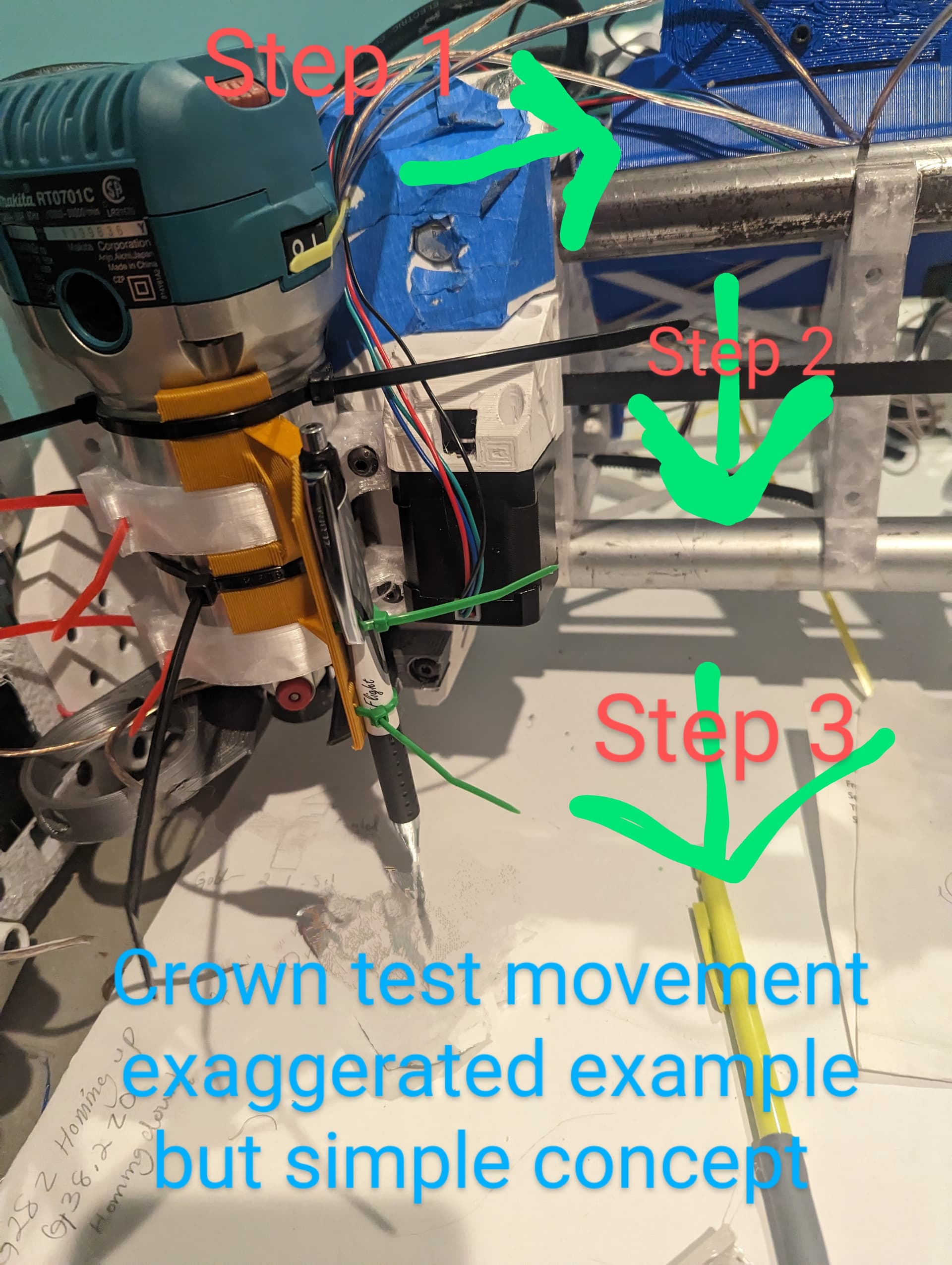
Same results actually now when I do run the crown test it works fine .
My biggest concern now is that when I move the y axis by it self it works but now when homing just the y axis the motor on the right of me doesn’t operate so it’s only one side moving which never happened to me.
I did run the test twice
OK, if there are stepper motor movement issues, it’s down to either wiring, or loose grub screw, or firmware. Since it was working, then not, it sounds a whole lot like wiring issues. A firmware issue usually either works or not, and is not intermittent. Anytime you have something that was working and then stopped, it’s likely a wiring connection issue. It could also be a loose grub screw.
Also, I have had wiring issues to cause stepper motor to make a grinding sound!
It’s strange but I’ll have a look.
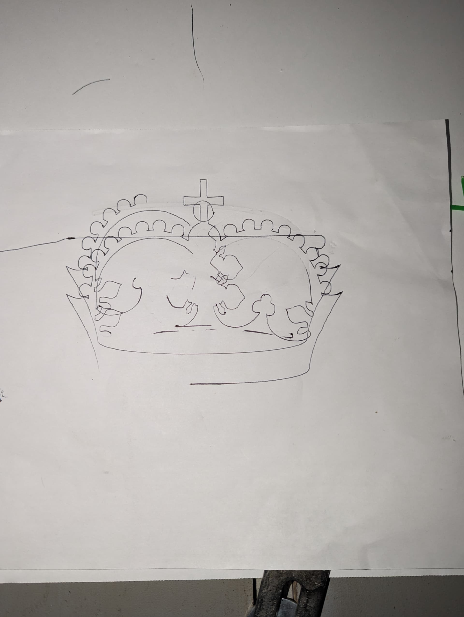
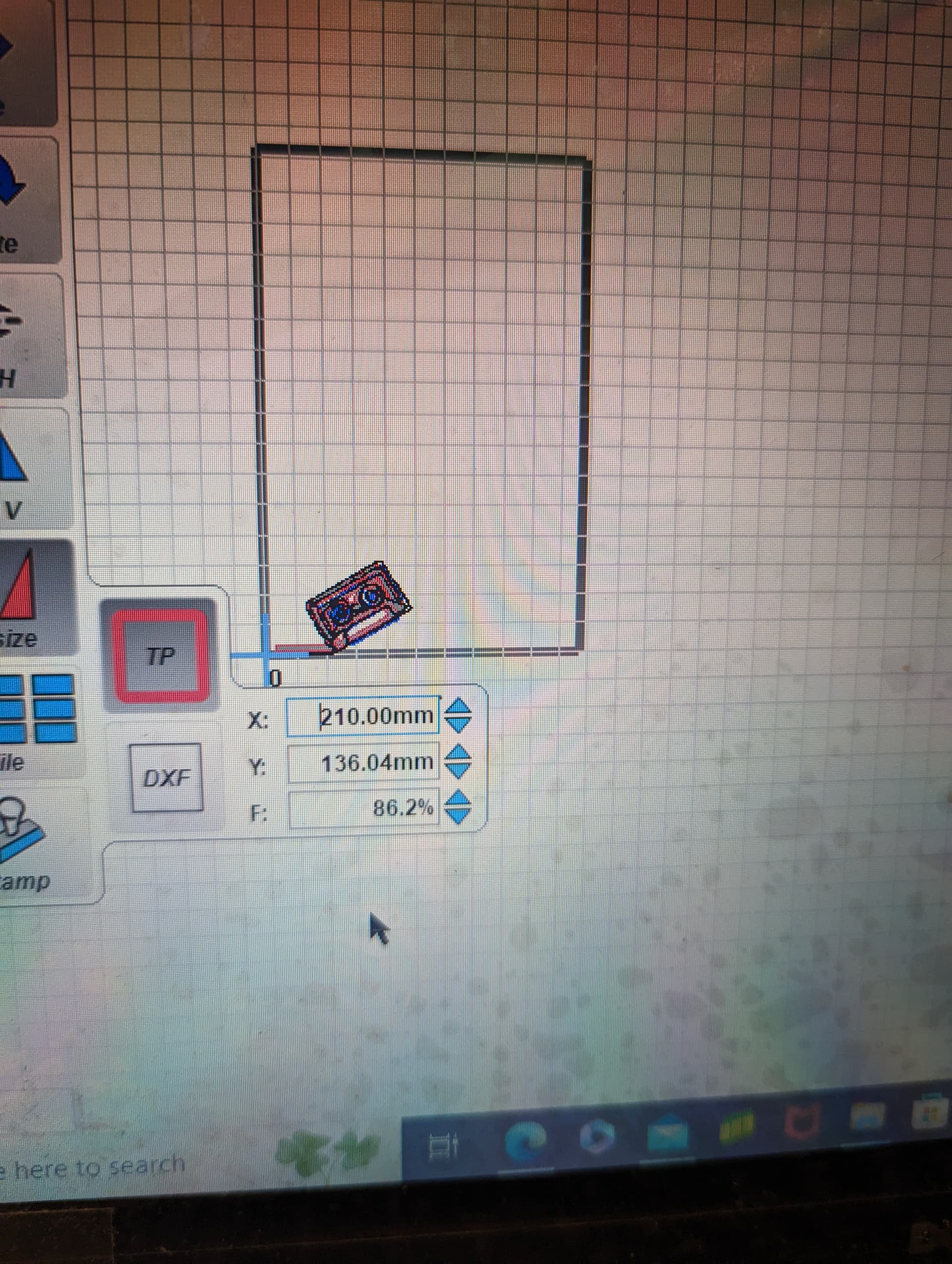
Make sure the paper doesn’t move. ![]()
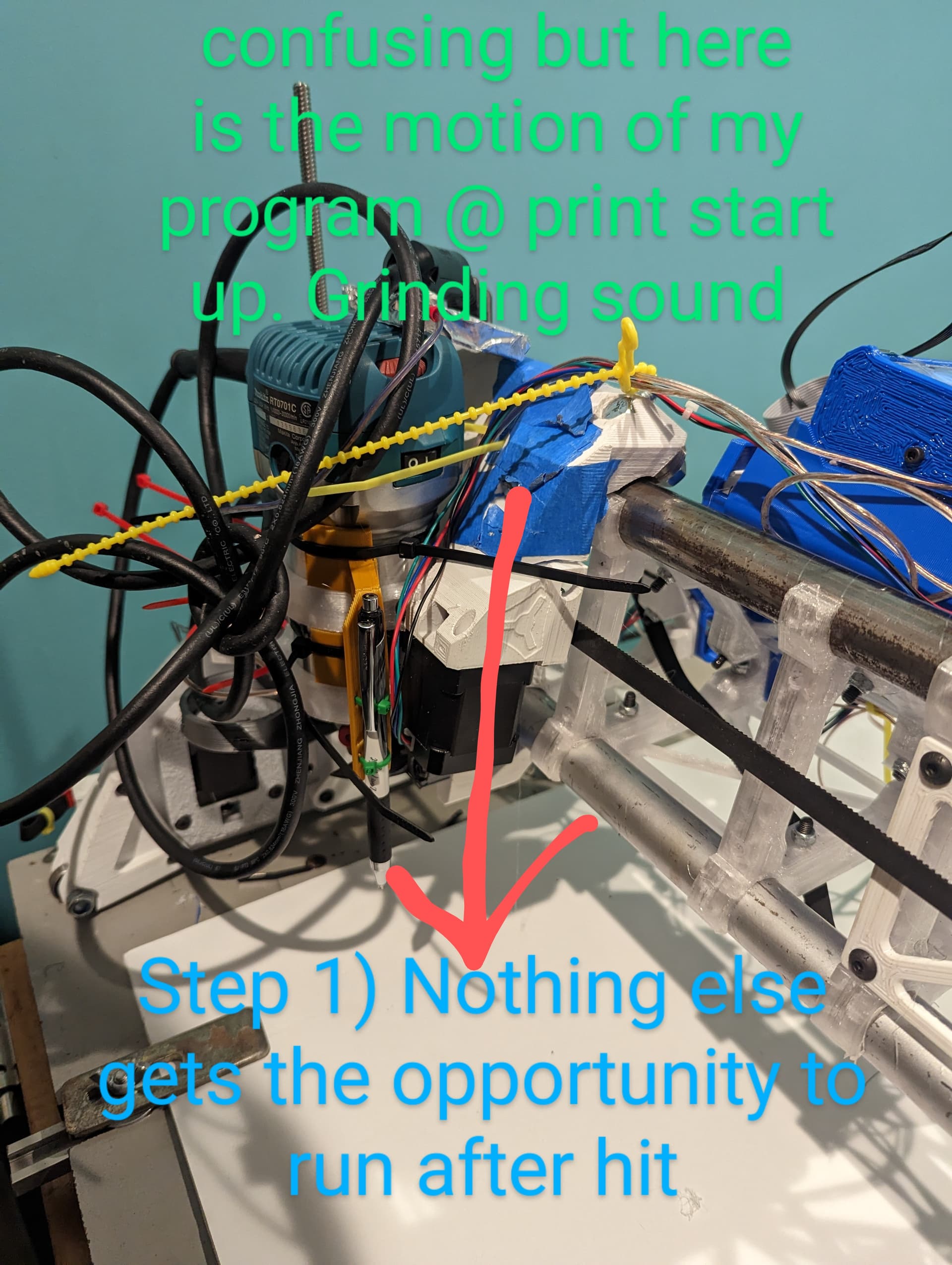
Right ! Although I noticed when I use when it starts it hovers above and then dips into the canvas.
My project just bottoms out without hovering. Very confusing at the moment.
And you are zeroing the Z at the top of the paper?
Does your Z movement work correctly for homing? and for zeroing? It only goes haywire when you start a print job?
Correct everything functions correctly but it could be what I put into Estlecam
The word “homing” is confusing. When you click any of the buttons labelled “home”, the machine moves until it feels it’s endstops. On X and Y, those endstops are at the machine zero. The Z is at some large machine value (200).
In CNC, we don’t care about the machine zero, we want the work piece zero.
In between homing the machine, and running the gcode, you need to tell it where the zero for the workpiece is. Where should it start counting?
There is a lot of this info laid out in a doc:
docs.v1e.com/learn/coordinates
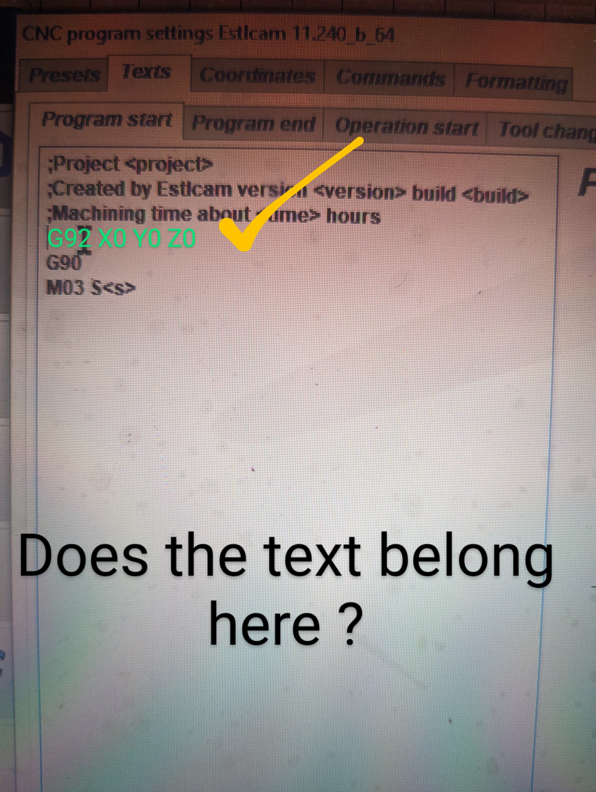
The big difference between your crown gcode and the test crown is that the test crown has G92 X0 Y0 Z0 added to the begining. That resets the zero when you start playing the gcode. Every move after that is relative to where you started the gcode.
So, you have two options:
Okay… I think I see.
The test crown gcode runs a G92 X0 Y0 Z0 at the start of the code, so you don’t have to home the Z axis, you just have to have the tip of the pen in the right place.
The G92 command tells the machine “This is where zero is” but Estlcam does not do that by default.
You can ADD that to the startup code, but usually I don’t like to for myself. I much prefer to set the machine up before hand.
So, you can probably run the same code that you have for your drawing, but use the touch screen terminal to send a G92 Z0 command when you have your pen set to the correct height.
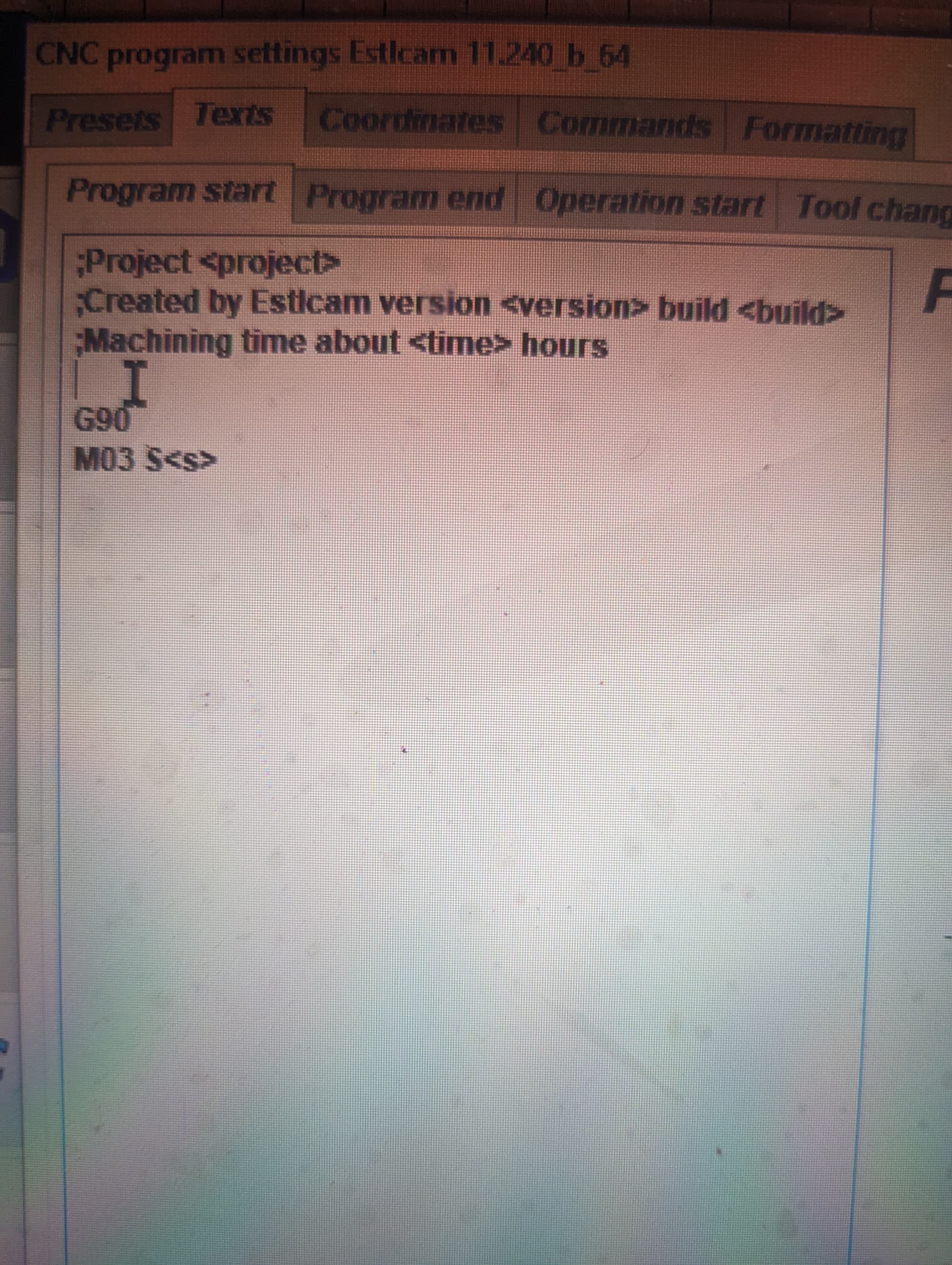
Hey fellas just to confirm where my cursor sits. In this image is considered the top of the gcode ?
Please indicate with a simple obvious mark showing what line is correct ![]() thanks
thanks
G90 (Absolute positioning) is the first line that gets executed.
Blank lines are ignored. Anything after a semicolon ( ; ) on a line is ignored by the machine and exists as a comment to make the file easier to understand by humans. Some programs do read the comments for data. For example, slicers or CAM can put information about total expected processing time or parameters that something else will read, but the actual machine does not do anything with that text.
Edit: further, some of the text in angle brackets means something to Estlcam, and it will substitute text for those fields, like fill in the version number, the date, the total estimated time (which may or may not be imterpreted by your Gcode sender or display)
You can put it there. If you do, no matter where the machine is when you start the gcode, it will set that as the origin for your coordinate system