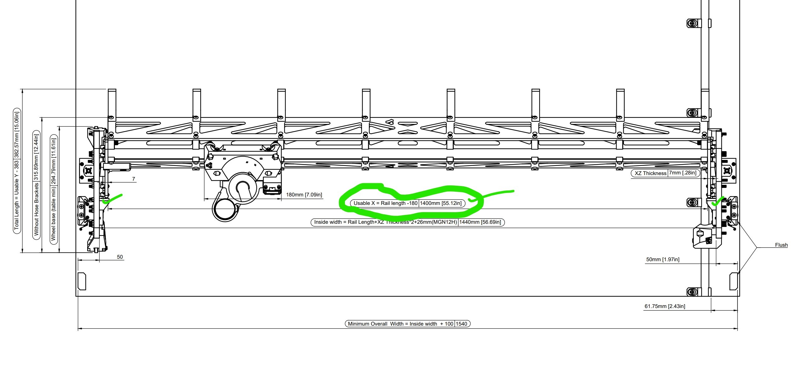
Hey there I have an image highlighting the X-AXIS and the number I got just only measuring that portion nothing else was 28.11".
What I’ve done for my Y-Axis is simply just measured my table @ 47.125", I’m just looking for a second onion when it comes to the actual table size that I will have overall for both sides.
I appreciate the help again
1 Like
The calculator should help, doesn’t it?
https://docs.v1e.com/lowrider/calculator/
As @Tokoloshe mentioned, the calculator is a helpful tool. I’m trying to understand in order to hopefully help.
In the drawing it’s setup for 55.12" (1,400 mm).
When you wrote “I got just only measuring that portion nothing else was 28.11”…"
Were you meaning you measured the drawing in some modeling software? Or measured some dimension of a real world table you have? I’m trying to understand where the 28.11" came from.
28.11" came from My gantry but I was just using the same method
1 Like
Got it. As mentioned above, I would suggest using the calculator. If you find after using the calculator that you cannot achieve your desired cut area width given your existing table, you can squeeze more width in by “flying“ the belt tensioners out in the air off the edge of the table, using extended mounts. The same method can also give you more length, by attaching rails to the sides of the table, and having those rails be longer than the table and putting your tensioners on those rails. Finally a combination of both of these ideas, using side rails that are longer than the table, and putting width extenders on those rails to fly the tensioners out further can result in an increase in both width and length, maximizing the use of your existing table. I will look up a link to an example where I have done this very thing, and send it to you.
1 Like
I should add that the side rails can be made of wood, or metal. An affordable strong way to make them out of metal is to buy metal struts at your local big box home-improvement store. These metal struts are sold under brand names, such as unistrut and superstrut. I started off with wooden rails on my big table that I built. Then later I switched to metal rails.
In one of my most recently published modifications, I moved one of my long belts down into the center of one of the superstruts. This gave me one long side where I could load material on and off, without the belt needing to be removed first. It hides and protects the belt down inside the C-shaped hollow area inside the metal strut.
OK, I pledged to lookup examples and come back with links.
This link is my initial LowRider build log, and it details my table both with wooden side rails at the start, and later switching to metal rails:
This listing of mine on Printables gives the files for the printed extensions I used to get more width out of the same table when switching from LowRider v2 to LowRider v3:
https://www.printables.com/model/220187-lowrider-3-cnc-table-extenders-to-use-lr2-table-wi
Finally, I later built another LowRider v3, this time for CNC plasma cutting, and the need this time was to extend length and add some “table drop” — with no real need to extend the width. The three Printables listings below were parts I designed to make that happen:
https://www.printables.com/model/415326-lowrider-3-cnc-plasma-cnc-table-parts-mounts-for-1
https://www.printables.com/model/415298-lowrider-3-cnc-three-remixes-of-rail-blocks-181-mm
https://www.printables.com/model/257450-end-cap-for-12-emt-tube-v10
I was more confused on the cutting space but thanks again I believe it’s all sorted out I just took the measurements of each axis and subtracted each side by the size of the dimensions going (x axis 180mm and the y axis I subtracted by 382.52mm ).
I measured my y axis based on where the 2 seperate tensions edges meet up from the inner side and for the x axis I measured the length of the x conduit that supports each leg like in the image
1 Like
Hey fellas ,
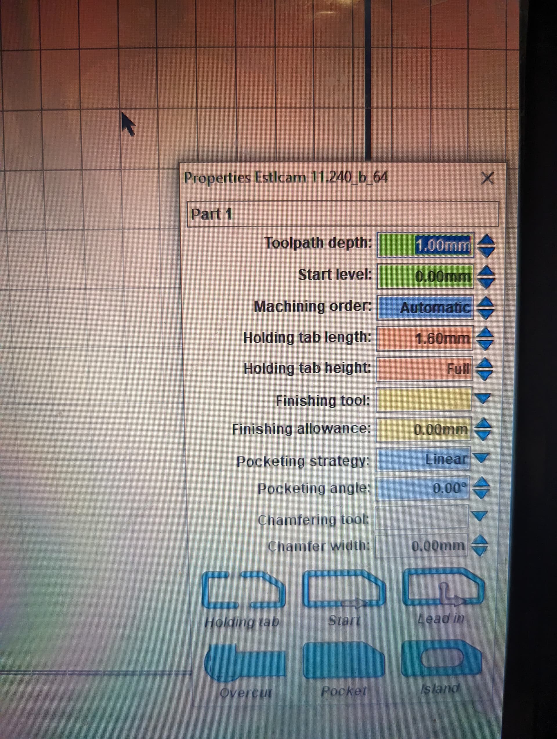
My newest discovery after trying for a round 2 is that my machine keeps bottoming out and I’m not certain to why is that here’s all the details I have plugged in . In order to complete what must be done before because no matter what I do with the start height in the machine it still bottoms out

Can you give us a little more details?
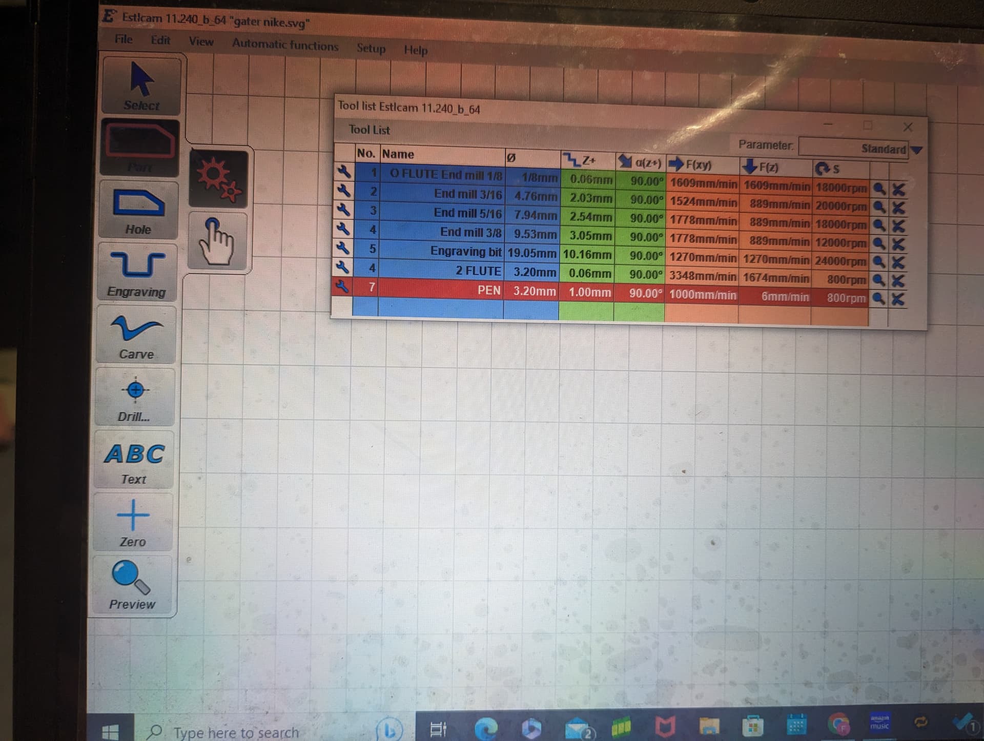
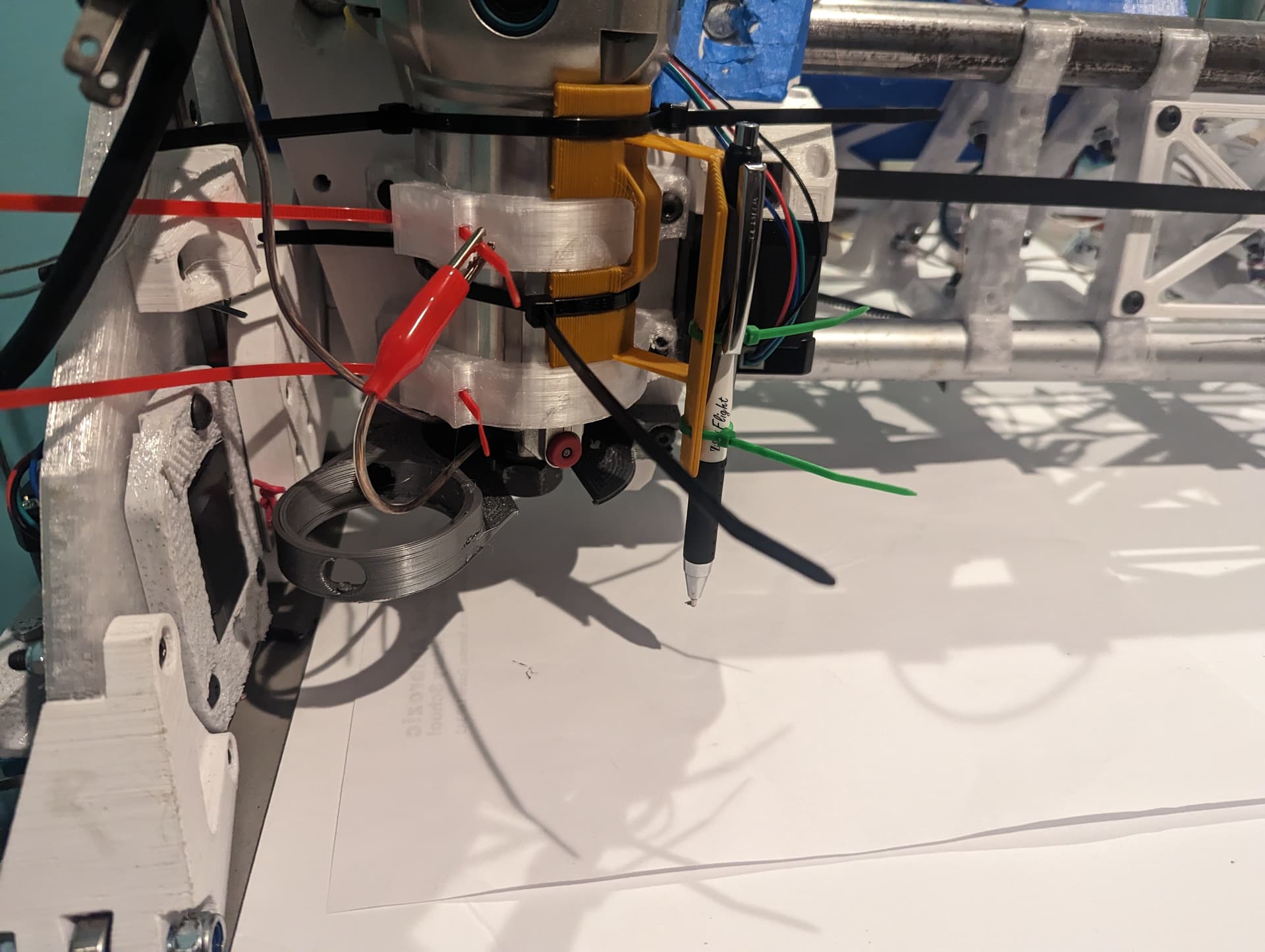
Pretty much I’m using the pen holder I done a outline with the part tool on estle cam. The high lighted tool is what’s being used.
In ESTLcam are you using the v-carve option? If so that would potentially cause “bottoming out” with a pen, because v-carve calls for depth based on width of area to be carved.
Nope only the selected option
It has been a little while since I messed with that, but I think you want the engrave tool rather than the part tool. Also, make sure when you preview the outputted gcode that it only shows one pass around, instead of multiple passes, ie you don’t want stair-stepping down.
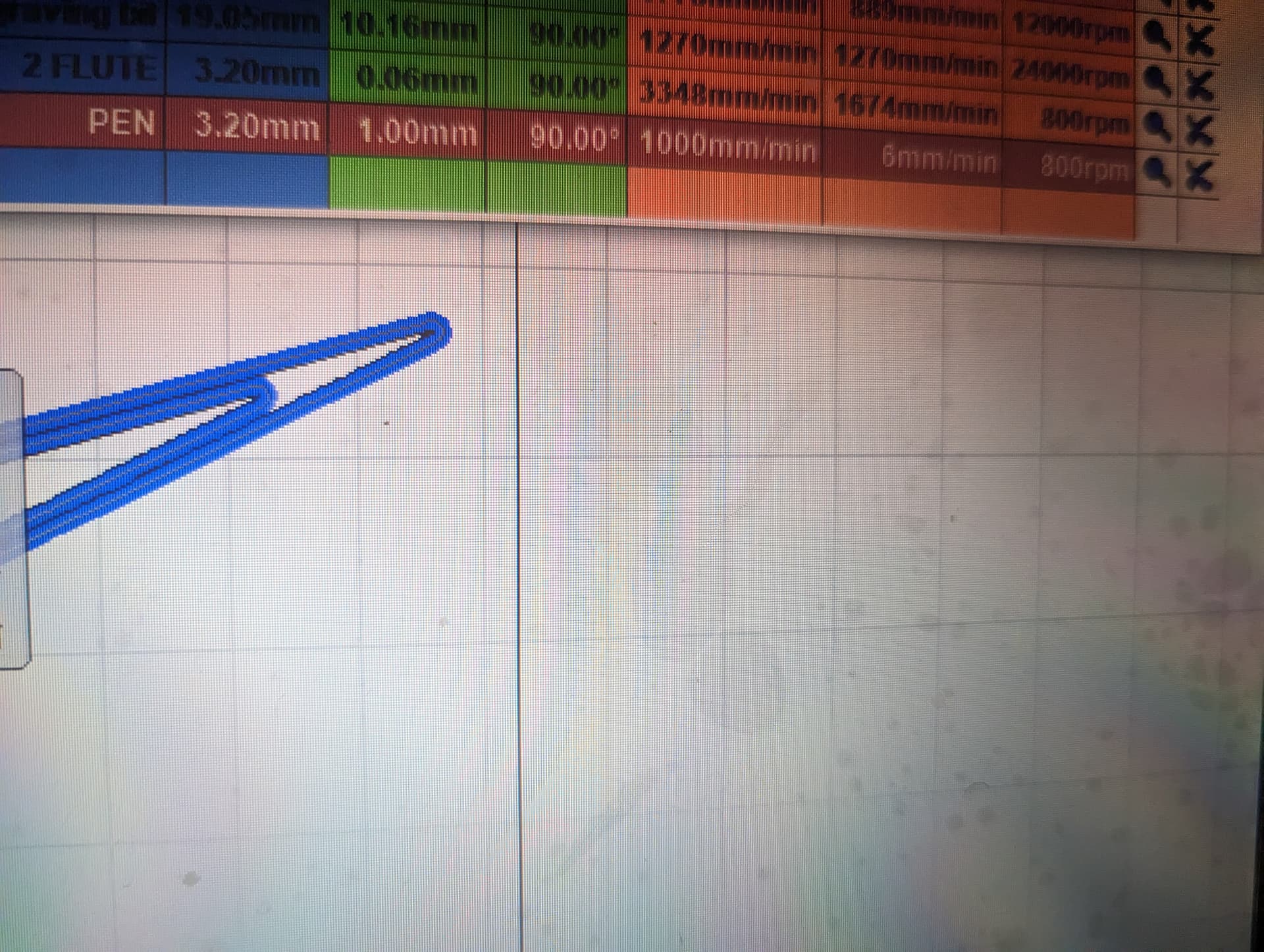
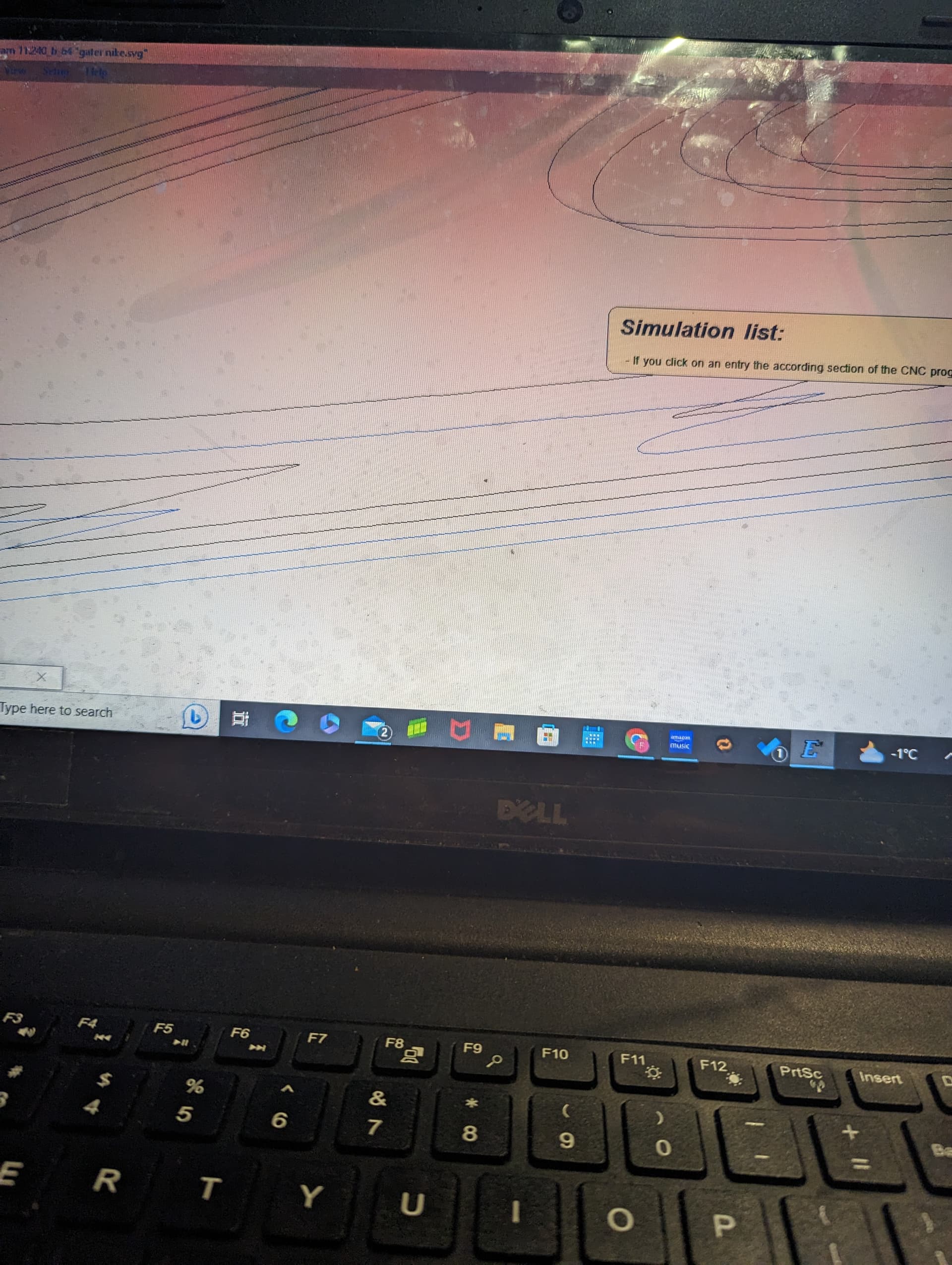
When you output Gcode in ESTLcam, before playing the animation, you can tilt the displayed graphic, so that you get a bit of a side view, and this allows you to see how many layers of passes are shown— again, before you press the play button. The moment you press the play button, all of that detail disappears so that the lines can be drawn in the animation style.
From the first image (post above) I cannot tell if you are seeing more than one pass on the part “cut” for your drawing. Is it one pass or more than one?
As far as I can tell from a prior image and the latest one, you have the tool set for 1mm step down, and the part cut set for 1mm depth of cut, so there should only be one pass.
Yes I definitely clicked onto the item for 1 pass only nothing clicked twice . Everytime I set up it’s in this position (according to the image into the post ). Is there a setting that I’m not doing correctly?
Additional passes are not supposed to be programmed by clicking twice, but rather by the relationship between the tool’s “Step Down Depth” and the tool path’s “Depth of Cut” — if your tool is programmed for a step down depth of 1mm, and your tool path’s depth of cut is set to 3mm, then you would have 3 passes.
By contrast, if you “clicked twice” to create a duplicate of the same “Part” tool path, and assuming it gets assigned the same depth of cut, then you would have two “tool paths” (not “passes” per se, but “tool paths”), both at the same number of passes and all passes in the one duplicate being at same depth as their counterpart pass in the other tool path.
1 Like
The above image is what shows if you’ve clicked more than once and created duplicate tool paths, and you try to select one of them, and ESTLcam cannot tell which one to select.
1 Like