I have really only had the Z post nuts spin on me. Part of the issue I think is when im using the screwdriver im trying to push up on the screw to keep my screwdriver head from slipping. By pushing up, im also pushing up on the nut to where it is not seated all the way down and that may be allowing it to slip. I’ve overcome this somewhat but using another blunt edge tool to push down on the nut while im trying to screw the screw from the underside.
Even after prethreading the nylocks, they can still be troublesome. But this is only like 1 out of 30 tries or whatever. It happed a couple times on my Primo build. And this could most definitely be operator failure on my part
Do you feel like regular nuts would do just as well as nylock? Or do you think that they will allow screws to unthread themselves overtime? I think with the belts always keeping tension on the screws that even a regular nut would have enough shear force between the threads to cause enough friction to not unthread. I am not sure though
Yeah im curious to see how that works out. I’m going to continue with the lock nuts for the remainder of the build, no problem at all. For applications like the milling machines I can definitely justify lock washes with all the vibrations and such.
So. I determined the cause of some of my threading issues. Stainless screws on stainless nuts. Screwing stainless on stainless threads with no lubrication is a bad recipe, especially with the back force the nylon puts on the threads. So when I am pre threading them and backing them out over and over again, I was galling them up and some of them got bad enough that there we just stuck together. Once I realized that I started putting anti-seize on the screws before threading the nut and that makes a world of difference.
Too bad i’ve already put together 90% of the machine without using anti-seize…
I also accidently cut my last strip of belt in the wrong place and now its too short. Need more belt for the last Z axis assembly. Dang. Patience is slim
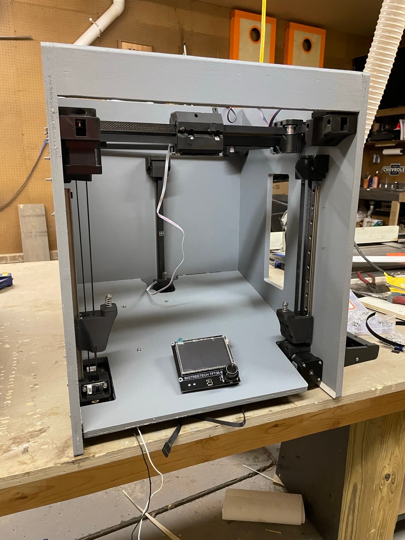
So I finished with the mechanical part of this build yesterday. Everything is installed, except for the Hemera and build plate. I can begin wiring and testing without those installed.
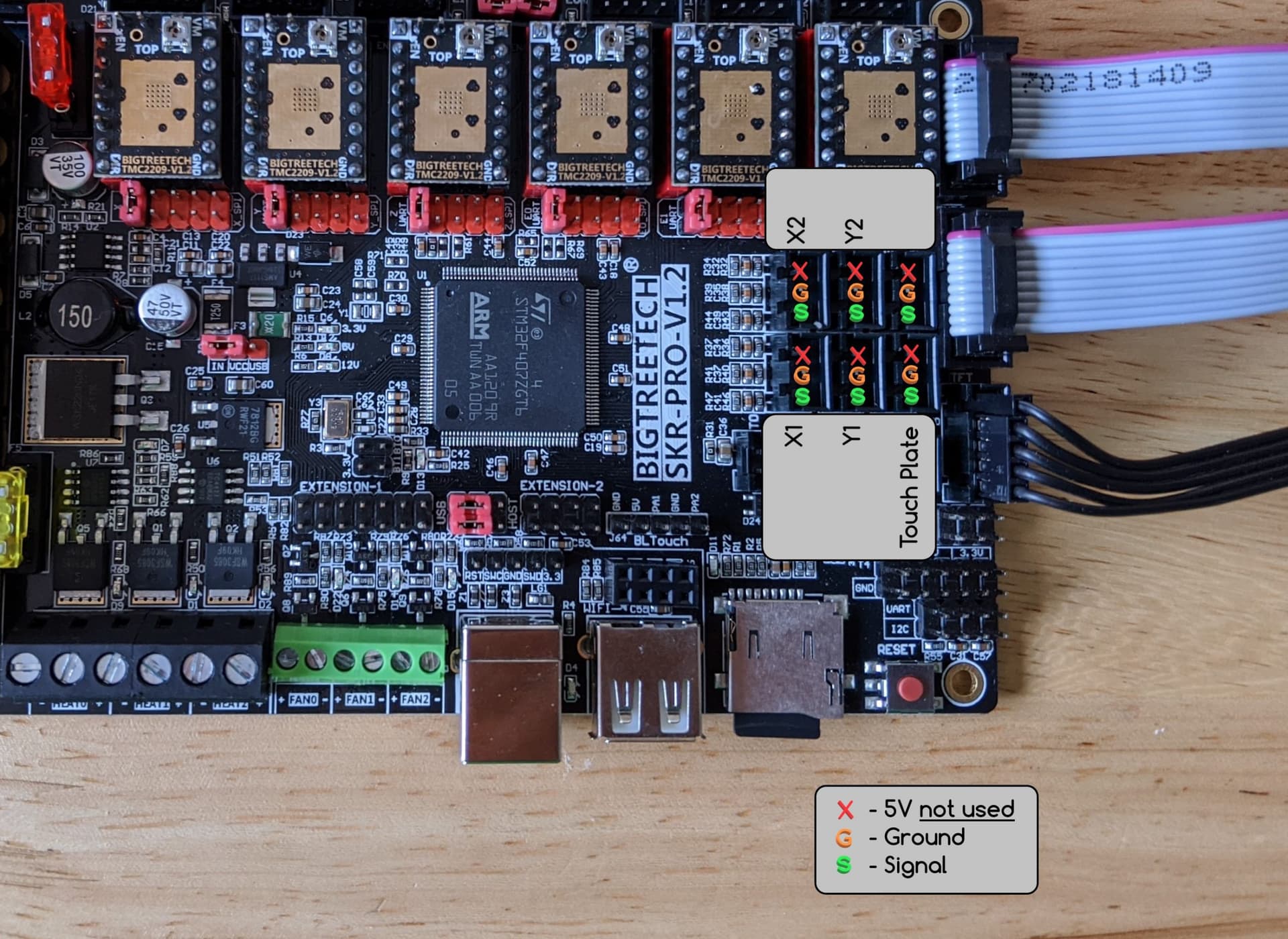
Now for the wiring and such. This is where I get pretty squirrely. Any tips/tricks/advice about wiring this thing up would be greatly appreciated. I know I will need to solder some extensions on a few cables, that shouldn’t be a problem. My only worry is plugging something in incorrectly and making an SKR Toast 1.4. This is my first time using an SKR board, i’ve always used Ramps so bare with me. Ill start with some questions that I can think of off the top of my head to get me started:
TFT35. I know EXP1 goes to EXP1 and same for EXP2. But what exactly is the other cable with DuPont connectors? I assume that is for the touch ability, is that required?
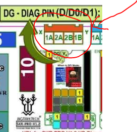
TMC2209 drivers. I need to bend the sensorless homing pin out of the way and remove the jumpers to set it into UART mode, correct?
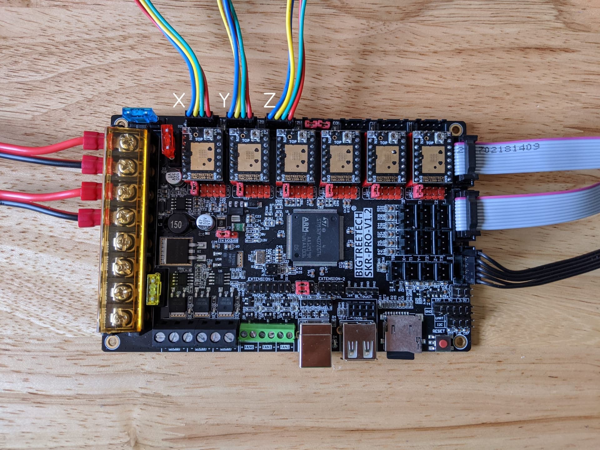
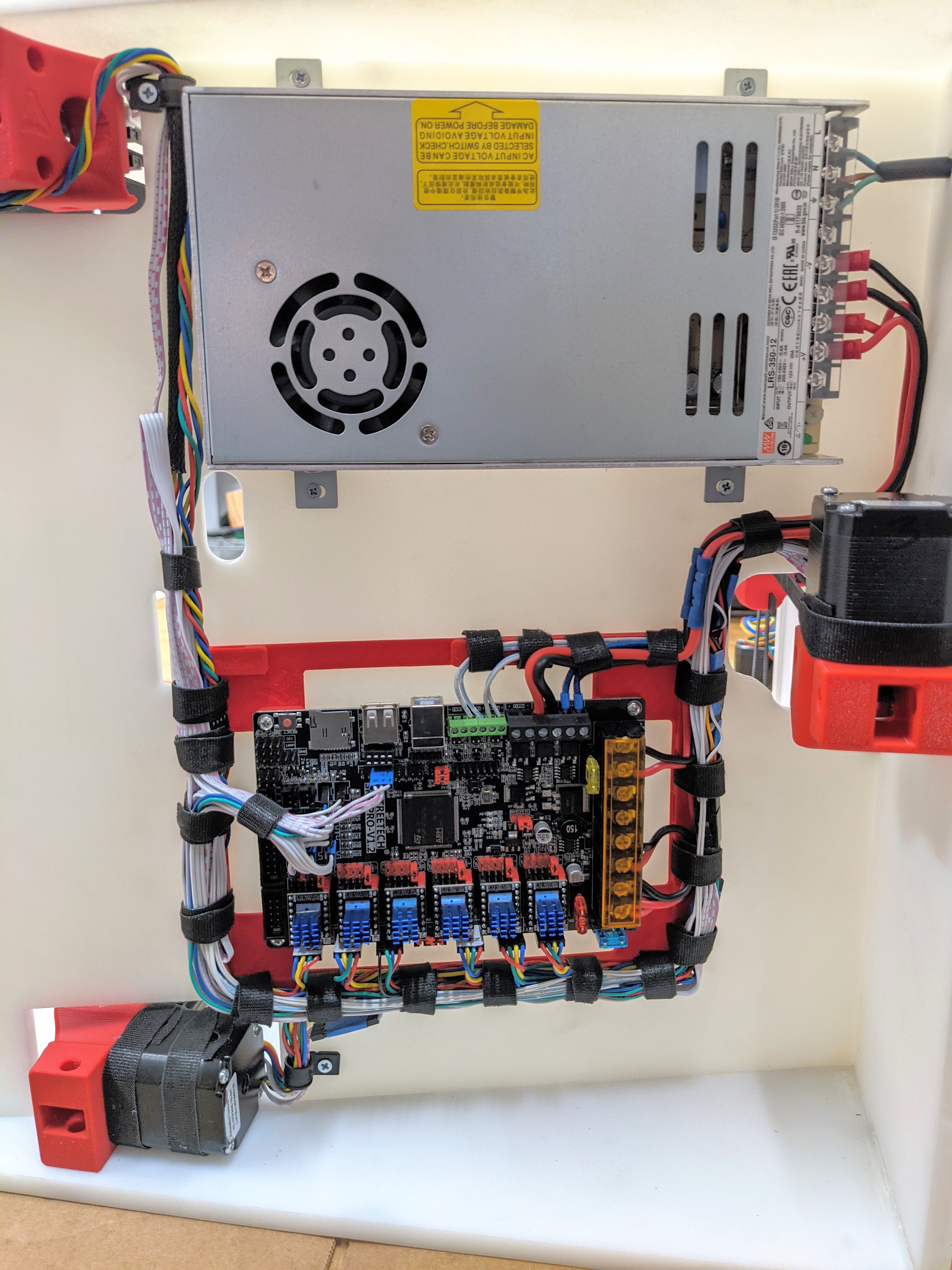
Stepper motors/axes. In this picture, are the stepper motors X, Y, Z1, Z2, Z3, E from left to right? Whats the configuration there?
Stepper motors. What constitutes a coil pair, the number or letter? I want to make sure I have these wired up right before I solder them and test it just to have motors that shake all around. Do you think I will need to switch up the order between motor and driver or should it be plug and play? I assume every brand of steppers have differently arranged coil outputs.
Endstops. The wiring/pin layout is straight forward, but what is the layout for the axes on these? X, Y, Z1, Z2, Z3 in what order?
TFT35 again. Flashing firmware. When flashing firmware to the Ramps boards I usually do that with USB port wired in and use Platform.io. Is that doable with SKR or does it have to be flashed with a microsd?
That’s a lot of questions but I like to be certain of what I am doing before I do it so I don’t have to either redo it or potentially damage something because of my lack of knowledge.
Oh boy, there are a ton of wires on this thing. Take it slow.
Pretty much the only way to do this is a loose wire or The endstops, be very careful with the endstops, power into signal is a very bad day.
1)Yes it is for touch mode, not required but it can come in handy any day now when the fix gets merged. I use it for the built in terminal all the time.
2)Yes, same as the CNC’s’s
3)No. X, Y, Z1, E, Z2, Z3
4)Should be plug and play, makes a nasty noise if you are wrong but no harm potential. Letters are pairs.
5)Test with M119 in the terminal to verify one at a time if needed. I think it is xmin, ymin, zmin=z1, xmax=z2, ymax=z3. I will have to look at the firmware to be certain. Or the bl touch is Zmin (signal only) and the Z are the max plugs. Ping me if I do not verify this later. I need to do it for the instructions anyway.
6)both skrpro and tft are flashed with the sd card, remove the one from the pro after flashing.
The default wiring with my endstops was in the wrong order. End result was that I burned out the LED on one endstop, but it otherwise still works fine. It’s worth checking that the wiring is in the correct order on the plug.
I like the built-in terminal to send gcode directly without needing a PC, even if touchscreen mode is still bjorked. You also need the black 5pin wire if you want to use the ESP01S module for wifi, as that’s what carries the serial interface to the mainboard. It’s easier to enable the wifi port on the touchscreen than it is to enable it on the mainboard. The touchscreen is an update to the config.ini, the mainboard one requires you to recompile Marlin.
One area where I got things wrong with this was identifying which Z motors were 1, 2, and 3 respectively. Start from the front-left and go counter-clockwise. (3 is at the rear)
My endstop wiring is backwards too, I need to switch the S and + wires, which is just tedious soldering.
So explain the touchscreen and Marlin mode and whats going on with the firmware that everyone seems to be anticipating an update. Is there something special I need to do after flashing to make sure its set on the right mode.
Also, I’d like to explore the wifi ability at some point, maybe not right off the bat. Will that allow me to interface with the printer using Octoprint. I have some ESP01S modules already, is it just as easy as plugging into the TFT and enabling it?
Take a look at the connector.There is a small tab in the metal that locks the pin into the connector. Use something small and sharp to push that tab in, (I use a sewing pin) and you can just pull the wire out of the plastic. They push it back out again so that it will lock, and put it into its new position. No soldering required, just a little patience. If you’re good, you can pull the wire at the same time as you push in the tab, and don’t even have to bend the tab back out.
This works on the JST connectors as well as the duponts and most other ones.
Alright. Its been a while since i’ve made any progress here. I have been away for a while. But over this passed weekend I was able to put some hours on this build.
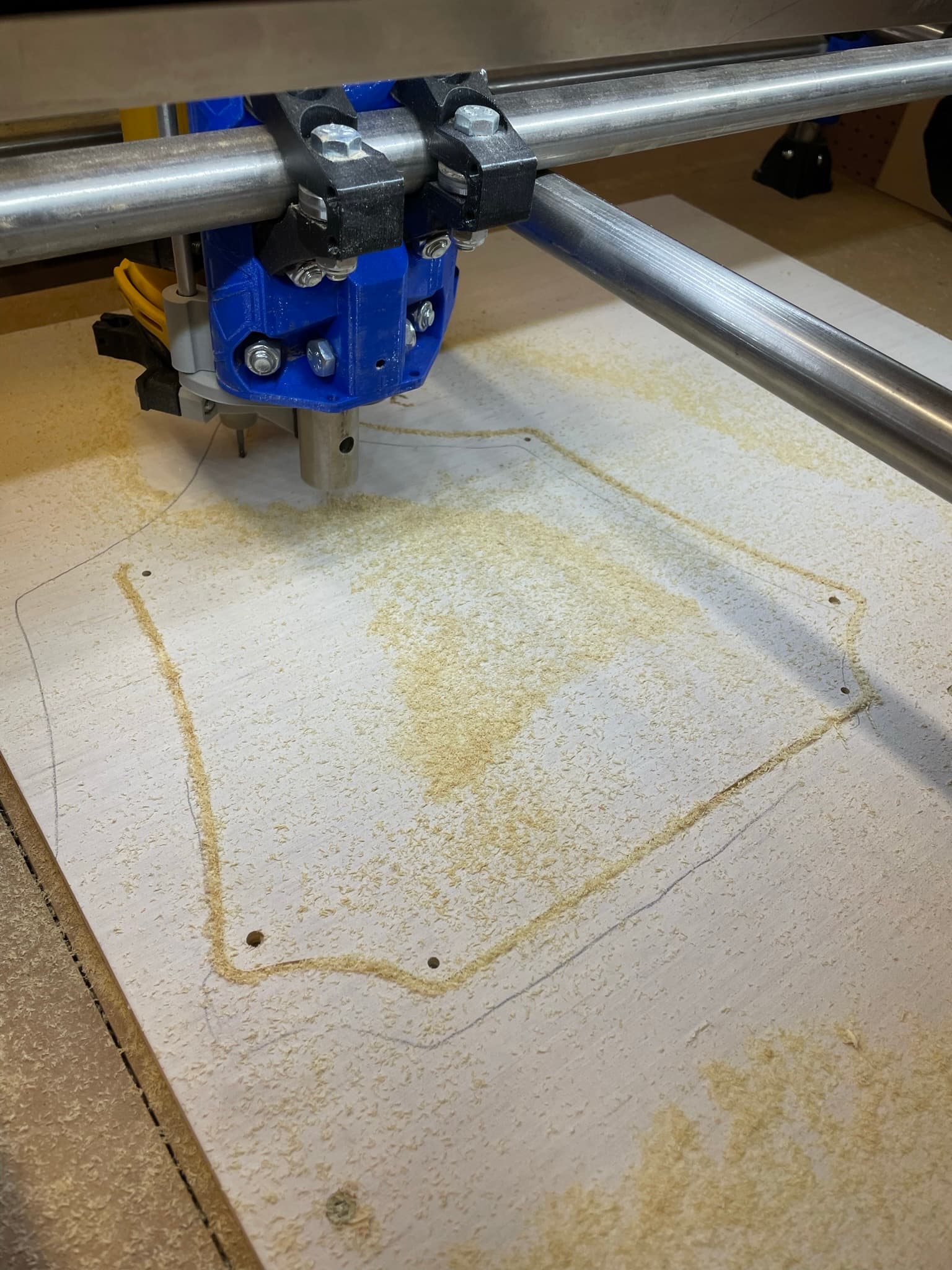
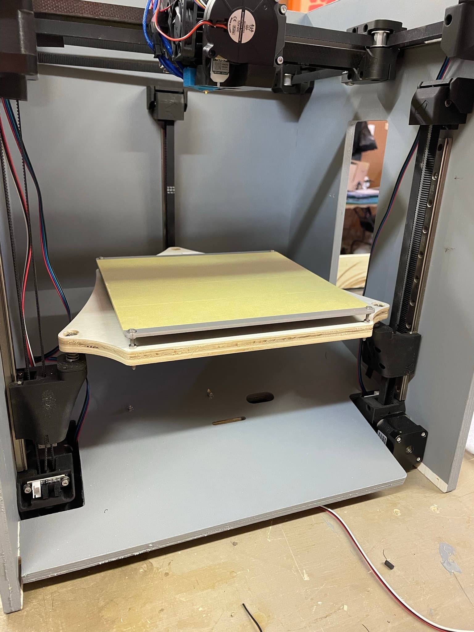
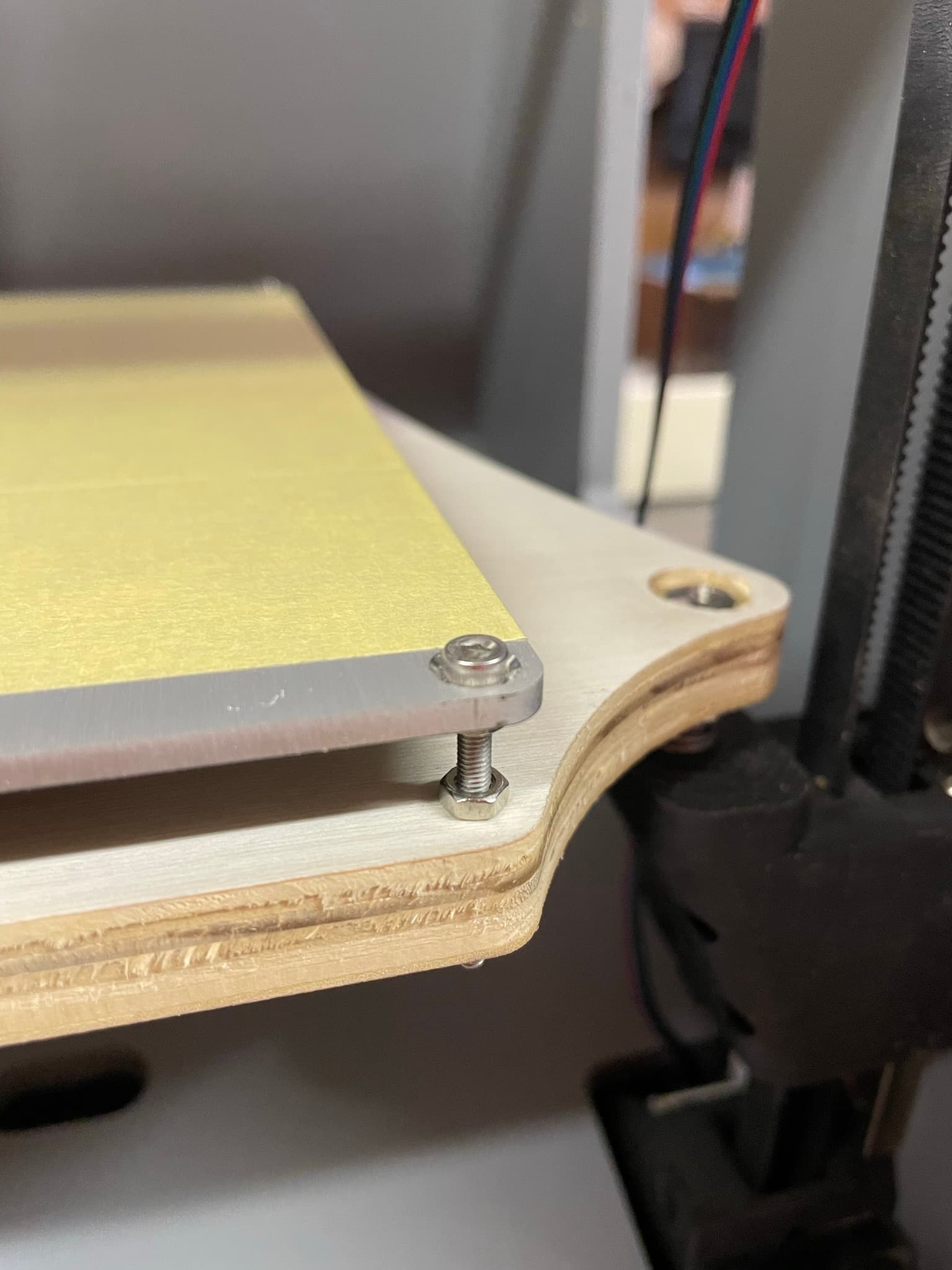
I cut a bed plate out that I modified to fit a 4-holed square mounting heated bed. I used the same 1/2" plywood that the machine is made out of because I had nothing better laying around. I think I will be changing this to 1/4" later. I need to take the bed plate off anyway bc it is not painted.
Also, I do not have countersink machine screws for the bed, which are obviously needed. Can someone confirm with me what screws these are before I purchase? I used the same M3 screws I have been using and they fit well so I assume I should get M3 countersunk screws?
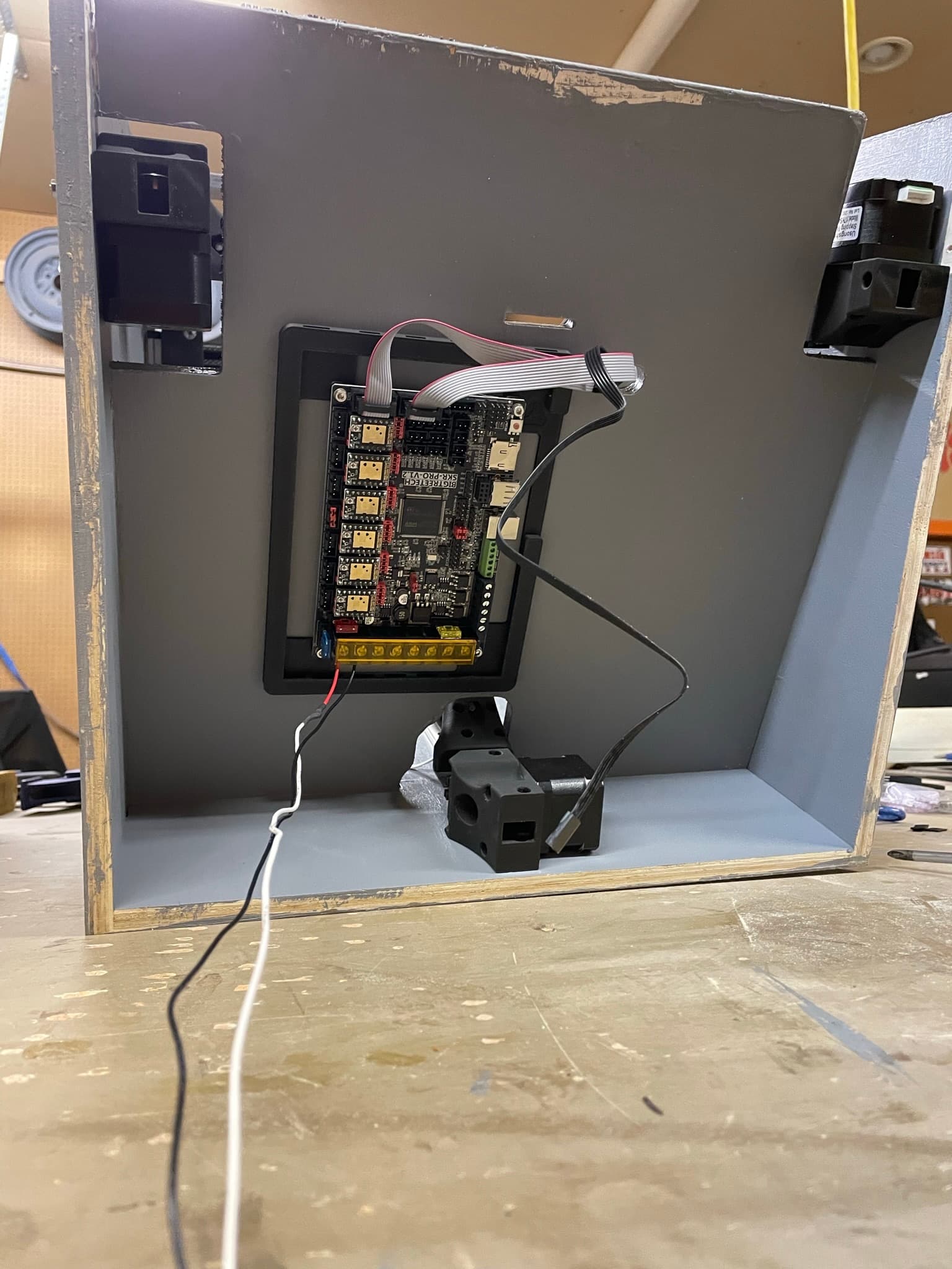
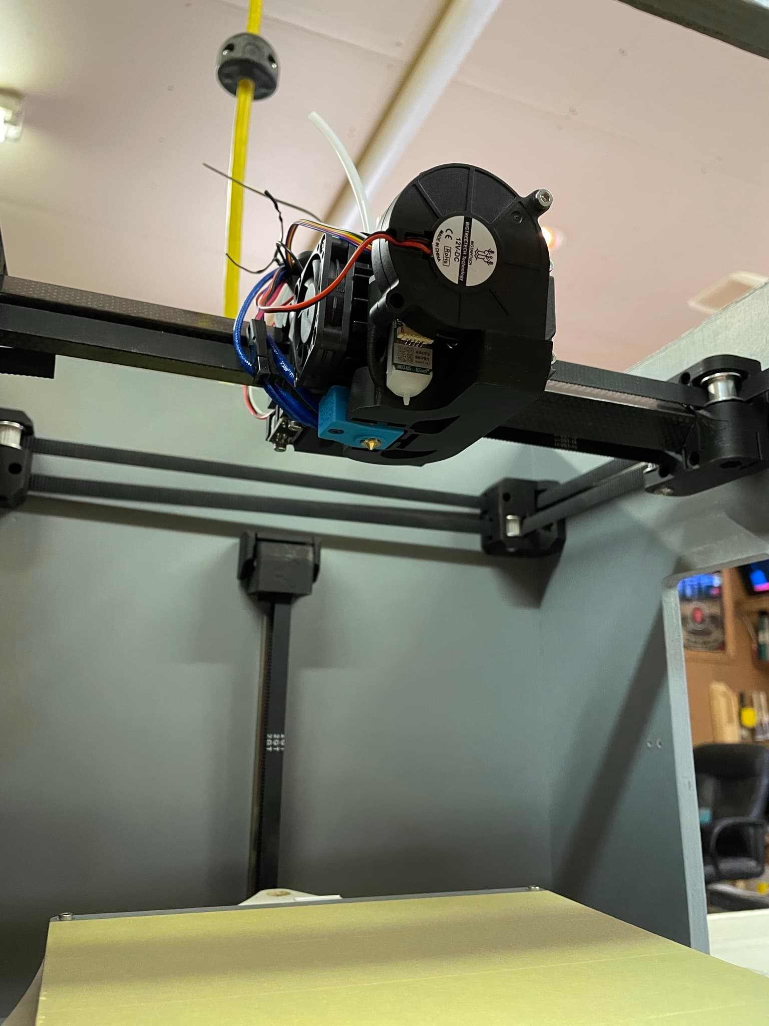
My goodness this gantry assembly has a ton of wires. With wiring being my weak point, this is going to be a real challenge to make sure I have correct. I have got all the steppers and endstops wired up already, except the ones on the gantry. I have the power supply put in with the 12v outputs ran to the 3 12V inputs on the SKR. So all that is really left is hooking up everything coming from the gantry and the heated bed.
Be prepared for more wiring questions coming from me in the near future. Thanks in advance.
M3 usually work for the bed. I have always had to countersink my own, must be a nice bed!
For the extruder, label each wire now. Tape and secure any connection on that umbilical or it will fail as it is always moving. The X axis endstops, I usually wrap that wire under and follow the hotend wires up and over, keeps things a little more tidy.
I do have a wiring diagram I keep forgetting to upload. I will add it to my notes right now. Ton of wires but should not be too bad.
Thanks for the tips Ryan. I definitely want to keep the wiring as neat as possible. Ill check out the wiring diagram in the docs, that should help a lot.
I think I’d just punch a hole in the plywood where my hand needs to be to turn a screwdriver. The side plate is bound to be sturdy enough for a liggtening/access hole.