Okay hopefully this helps a bit.
https://docs.v1engineering.com/mp3dp/repeatassm/#skr-wiring
1 Like
Yes that does help! So the terminal next to Bed Power is actually an output for the bed heat? I notice that in the picture of your wiring you are not actually utilizing that terminal at all.
Yeah that was just before I plugged in the bed. That is always the last thing I plug in.
2 Likes
The wires from the gantry are coming up just a bit short. Unfortunate. Especially the blue hotend wires from the Hemera, are these extendable? I am worried to cut these
Extending the wires is a pain, but yes, they can be done.
Before you do that though, see if rotating the SKR board 180° would make the difference.
If not… I would most likely just use a barrel crimp, or the heat-shrink solder rings to add on some silicone insulated wire. The braided fiber insulation is good for right near the heat source, but at the board end it isn’t needed, and regular insulation is perfectly good. I might choose to go with a heavier gauge for the extension, just to keep resistance low. Maybe 14-16AWG wire. 18AWG at the lightest.
The thermistor and fan wiring is pretty simple and can be extended with some light duty 20-22AWG wire easily enough. Same with the motor wiring, actually. The motor wiring and thermistor will need JST or DuPont connectors, so that’s annoying, but not too bad.
1 Like
Thanks Dan! I just flipped it 180deg and now going to continue and see if things will reach now. Hope to not need to extend anything now
1 Like
Next question. I am looking at @vicious1 wiring and he has something plugged into Heat 1. I know the Hotend goes into Heat 0 and the heated bed goes into power terminal block. So what is Heat 1?
That was a mistake, for some reason I plugged the bed in there…it’s fixed now but I have not updated the picture.
1 Like
Gotchya! Thanks for the clarification
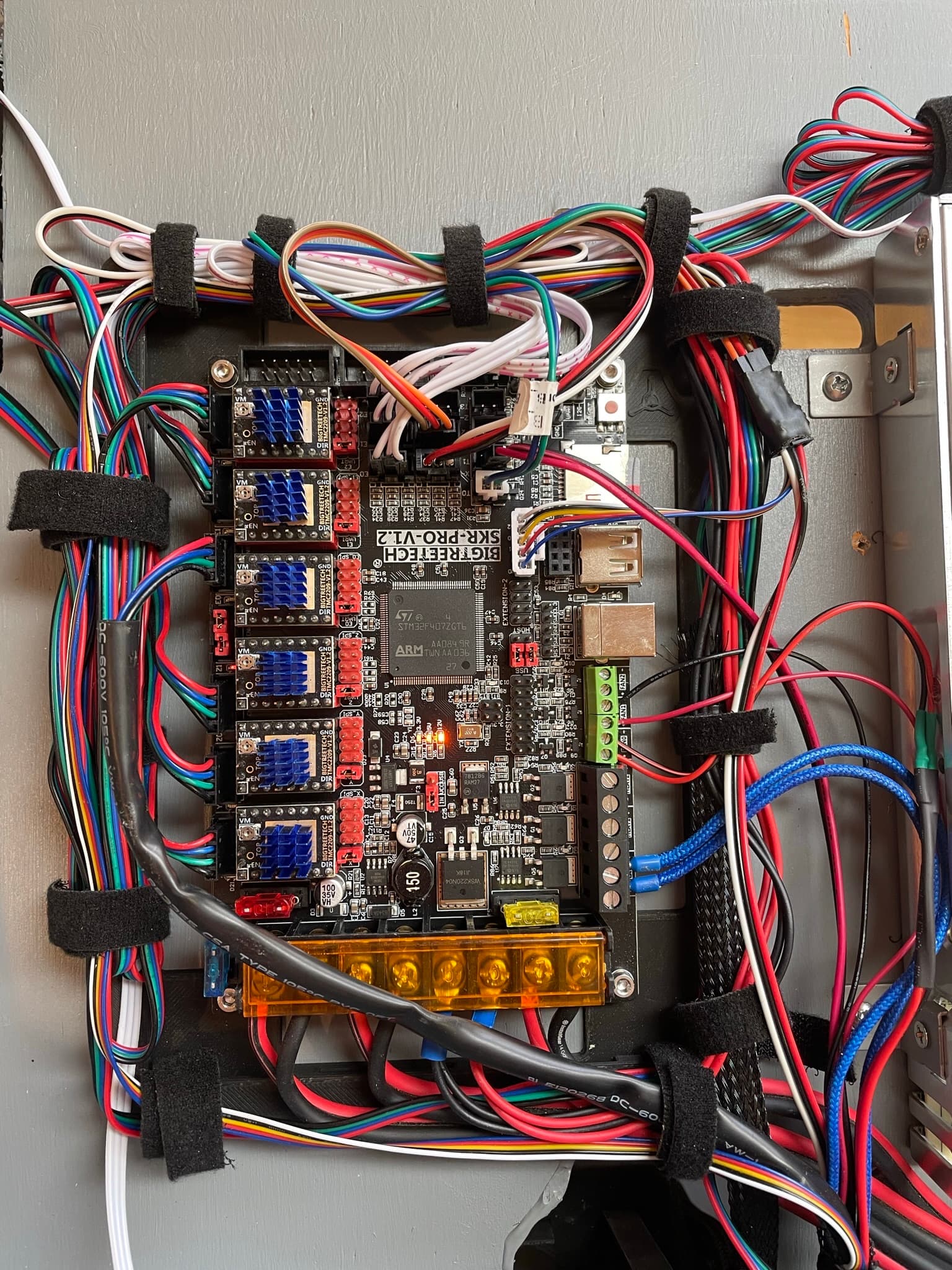
Alright guys. I just finished wiring everything up. I got the wiring as neat as my sanity will allow me, so I called it good.
I plugged in the power and flipped the switch and here is what I got. Just three orange power lights in the middle of the board and that was it. It’s hard to see here but there is also a very faint light on the left edge where the motor drivers are, whatever that means. I did put the firmware file in the SD card and I have the card in so I was expecting some green lights indicating the board was flashed. But nothing. What’s wrong here?
4 Likes
Check the SD card. It should change the file firmware.bin to firmware.cur if it flashed. (No reason why it shouldn’t.) It doesn’t take long.
The power wires on the bottom should go +, -, +, -, +. -, + - The third set in (Bed power) looks backwards to me. Bed power OUT probably doesn’t matter much, but the MOSFET for the bed isn’t going to like reversed polarity.
Edit… my eyes are crooked. Nevermind, mine looks the same
Hmmmm. Still says firmware.bin
Your BL touch is wired wrong.
If you still have issues verify the endstops are wired properly. The power wires on them can really mess things up. Power ground signal all need to be right or the board will not boot.
If you power it on you can trigger them to verify the light works on the endstops. When it is flashed the board will also get a red light when triggered.
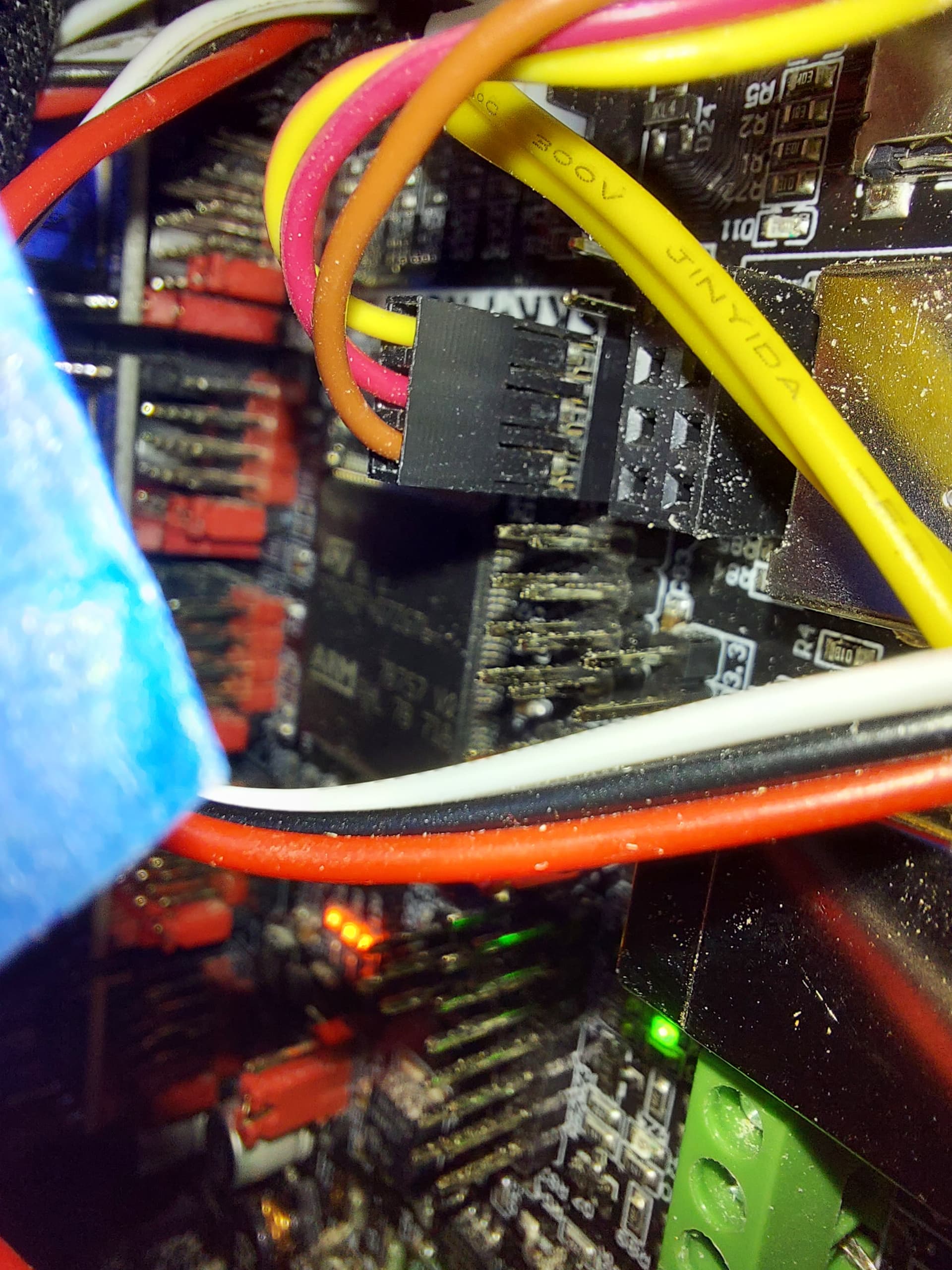
Does the BL touch just need to be flipped or is the JST configuration wrong? When I flip it I notice there is a red wire now on GND, which conventionally isn’t correct. Perhaps the wire colors don’t mean anything here.
I have it listed on that diagram I made. The three stay there and two go to the Zmin. Ground is sensitive on that thing as well.
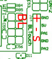
I see that its split 3 and 2 now. But now i’m confused by your labels. Positive goes to ground? If I knew which color wire went to what pin that would help alot. I am looking this up online and all the pictures I see have all 5 pins used on the one header. I cannot find an example of this exact scenario
This one is mine. It’s a clone, but the wore colour matches the docs I’ve read.
Black and white are ground and signal on the Z_MIN endstop line.
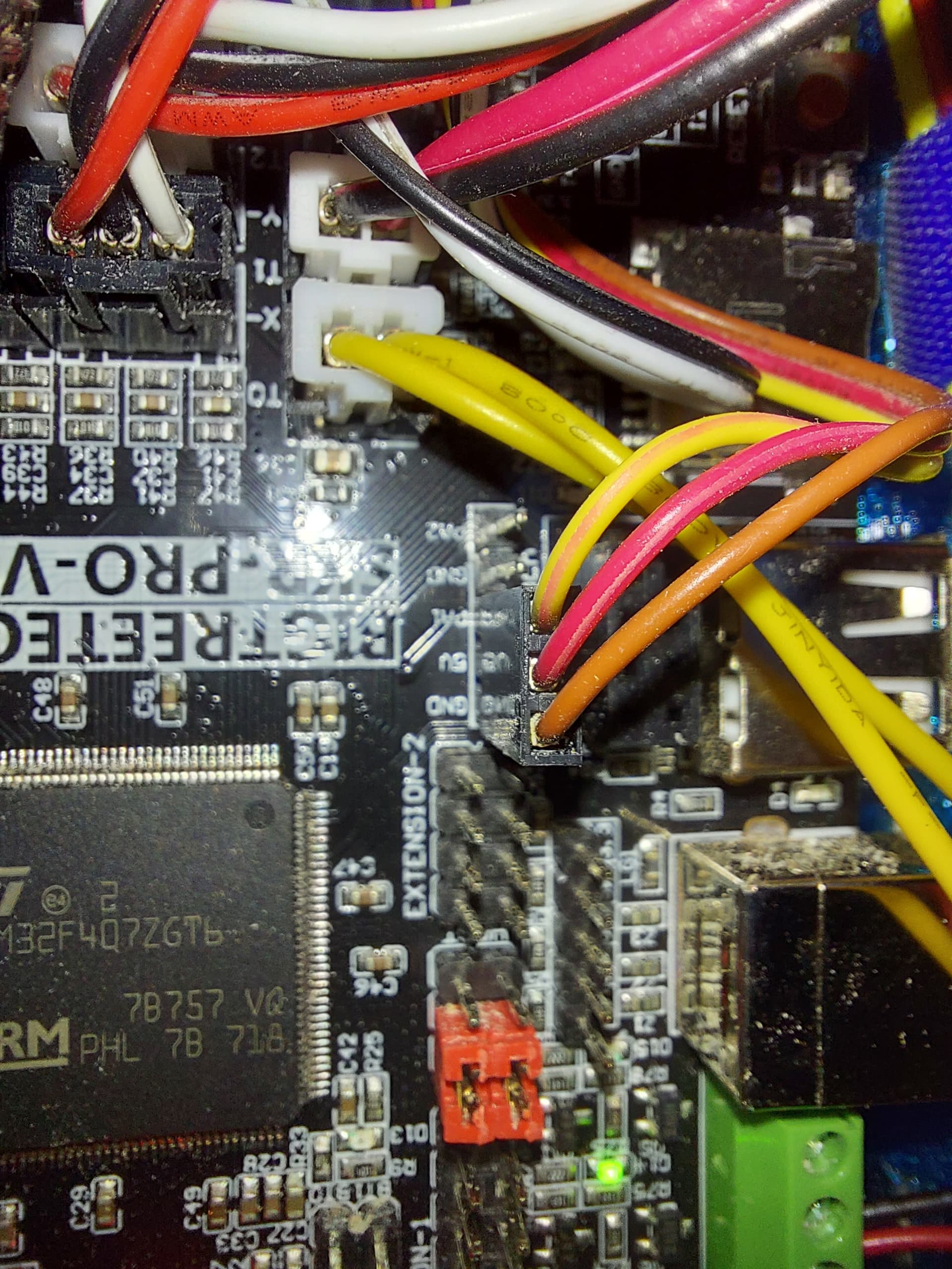
Oh dang that must be backwards. The board labels are right. power ground signal and the white and black go to Z min, black is ground there as well.