Matt's MP3DP Repeat Build

Tony hit it perfectly. Keep going, if the problems get worse V4 just takes another linear rail. The rest is reusable.

If you were careful you could even reuse your current frame, minus one part, which I could help make an alternative part or adjust your current frame.

V3 proved a lot of things, one of which is I got to wrapped up in challenging myself to make as few unique parts as possible. V4 is easier to build and easy to adjust and repair. initial leveling is rock solid this time around.

1 Like

I’m sure that the answer comes back to the old stand-by. “It depends.™”

One of the “big problems” with the Repeat is that the CF tube becomes inconsistent with use. The laminate starts to flex on the faces which lets the hot end move in inconsistent ways. This leads to more artefacts with stuff like G29 bed leveling where the wire harness tugging on the carriage starts to alter the trigger height of the BLTouch.

Honestly, I think that’s the only real issue, and it takes a while for that to really show up. Ryan’s printers are in a print farm and run pretty much continuously, so he’s going to see this worse than most of us ever will. I have more printers than I could possibly need, so mine doesn’t run nearly so much, and the only problem that the CF tube really gave me was that I could see some of the CF texture on the surface of otherwise very smooth prints.

That said, I’ve switched to 20mm aluminum tube. The aluminum is really smooth, of course, only a few grams heavier than the CF, and probably won’t develop the same flex on the faces as the CF tube did. I’m very happy with my V3 Repeat, and am looking to build another. I’ve paused a bit to think it over for if this should be another V3 or if I should go ahead with the V4, for which I’d need to buy another MGN12H rail. I have all of the hardware to go ahead with the V3 in hand already not to mention a complete set of printed parts.

My factors for building the V3 are:

  1. I am perfectly happy with my current V3. It works well, and I can’t see a reason why another wouldn’t also work well.

  2. At this point, the cost is the frame material. 12mm plywood still costs more than I’d ideally like, but the cost is likely to be the same no matter what I choose. (I have the wood, just haven’t cut it yet.) So the V3 is definitely cheaper for me to build.

On the other hand…

  1. “Gotta build 'em all” there’s a bit of that mentality to me.

  2. I do plan on having the printer around for a long time, and there might eventually be an issue that the linear rail would have made better.

  3. The Z axis on the V3 is sometimes annoying to adjust, I get some incidents where the belt touches the Z blocks on the opposite side, even when the belts are properly tensioned. This only ever seems to be a problem during rapid Z moves, like after homing starting the G34 leveling, or sometimes when homing after a print completes, but I’ve got one print that has a curve where the Z axis didn’t move evenly. The new Z shuttles look like they’d solve that problem. (This might result in a hybrid build, too, just take the new Z axis.)

If I had any kind of time crunch, I’d go with the V3. Full speed ahead and damn the torpedoes. Like I said, I’m happy with the performance of my current V3. Most of the current pause is really that I have 300mm rails, and I’ve hesitated on the decision to cut them down to 275mm.

If I didn’t have any of the hardware, I’d probably collect with the intention of building a V4.

So… It depends.™ I can tell you that I have no intention whatsoever of tearing down my V3. The 20mm aluminum rail goes a long way towards helping. I also have 3 CF rails that could be substituted in on relatively short notice.

1 Like

Thanks for the replies guys. I think I am definitely going to upgrade my machine to the V4 at some point. Maybe not right now, even though I just went ahead and purchased the aluminum extrusions… But I just wanted to have them when I am ready. As long as I can reuse all of the electronics/components then cost shouldn’t be too much more than the aluminum extrusions and another linear rail.

1 Like

Matt,
I did remix Ryan’s Repeat, to accommodate a linear rail for the X axis, and that made a huge improvement to the printer. The modified parts are not pretty (V1 standard) but they work, 4 parts to print plus a linear rail, and you are done.
I can post the files here if you want, or get them to Printables or thingiverse
The printer still going strong and very reliable.
I order parts to build the version V3-V4 what ever the number is :thinking:, all coming on a slow boat, but I’m keeping the original Repeat, as it has been the best printer I have ever owed.

3 Likes

Oh interesting! I would say definitely post them or send them to me, but at this point I have decided I am going to convert the one I have to the new V4 and reuse all of the electronics and such. I am not ready to convert quite yet, but it will be happening. If Ryan, never came out with this new version I would definitely want to switch the linear rail X-axis like you’ve done.

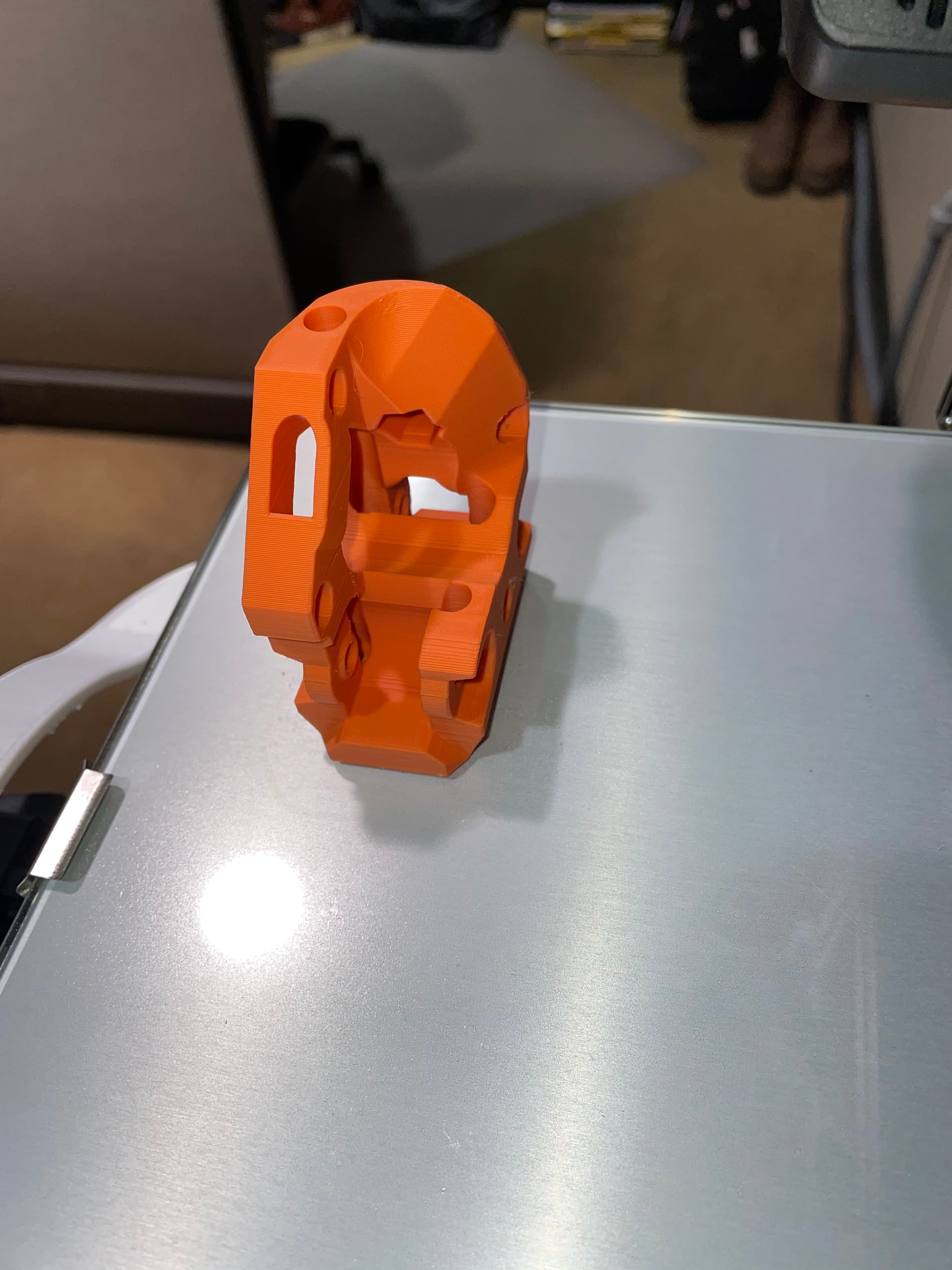
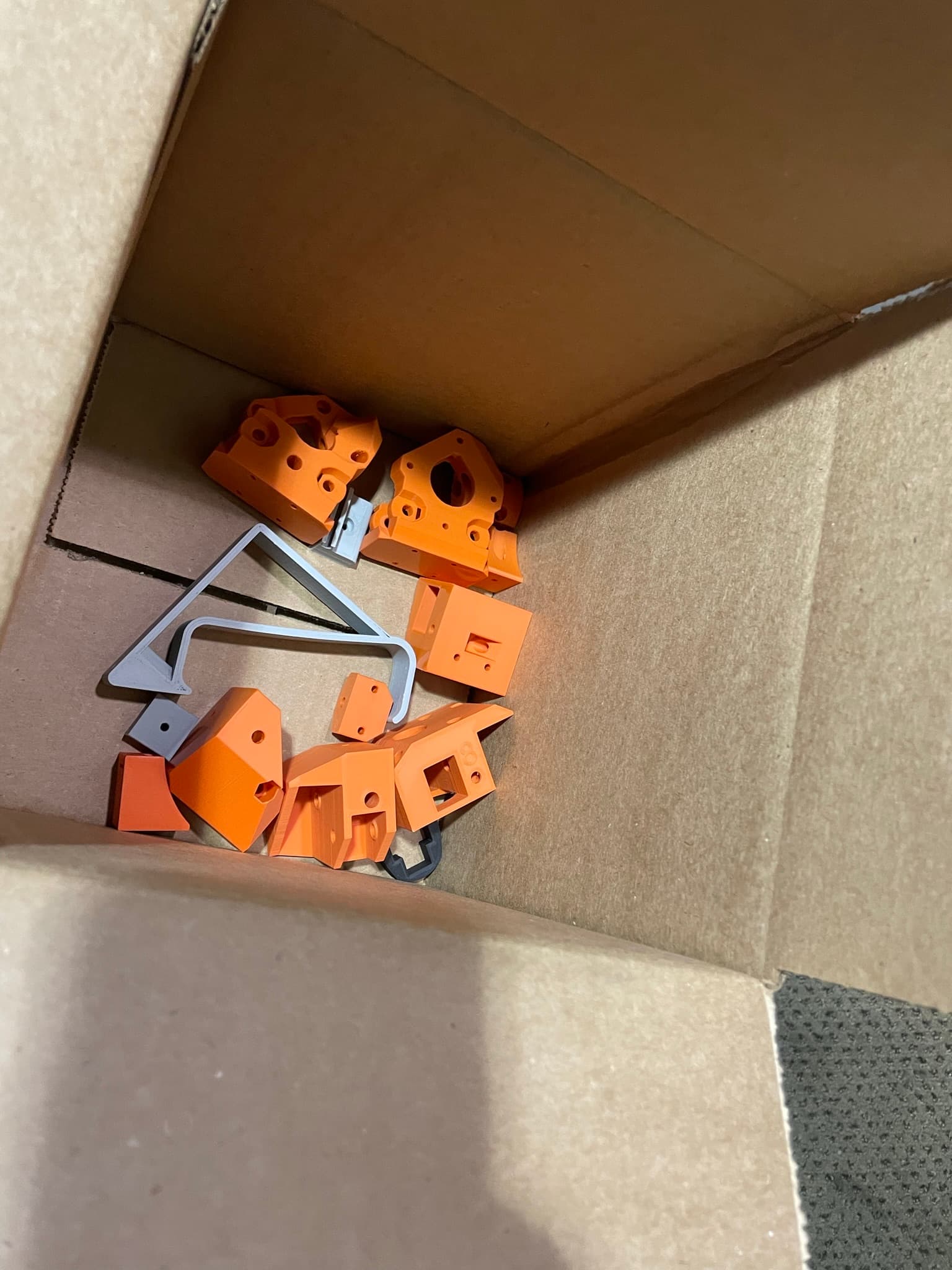
Somehow, some way, I accidently printed most of the parts for the V4 Repeat. And aluminum extrusions just randomly showed up at my doorstep the other day, not sure how that happened…

Guess i’ll just have to go ahead and get started on upgrading my printer soon…


5 Likes

Frame is done. The kit of aluminum extrusions with the brackets came with only M5 T-Nuts for the extrusions so I wasn’t able to start mounting the parts yet unfortunately. M3 nuts have been ordered.

A couple general questions:

  1. When disassembling my original Repeat, I lost some bearings when taking apart the linear rails. Those things come out so easily. Does anyone know where I can just order a pack of those little bearings or do I need to buy another linear rail to replace it all together?
  2. Another goal of mine with this printer is reducing the noise. Has anyone replaced the heatsink/motor fan on the Hemera extruder with a Noctua fan or some other low noise fan? Is a Noctua fan adequate? I will probably put a Noctua in the PSU as well.
  3. Will my belt lengths from the original Repeat be the right length to reuse on the V4, or should I purchase a new roll of belt?

1-The little balls can be purchased but you need to measure exactly what you have first. They are not standard. You can run just fine with quite a few missing. Or pop on out of each that you have until they are all missing equal amounts.
2-I have not tried that. I’m out in the garage with 8 running, I am not sure I would even notice. For me these are much less noisy than the V2’s.
3-You sure can reuse. Unless you beat your printer up they should be just fine and have extra.

  1. Ill measure them and may order a pack of them. You are right, they do still run pretty smooth with bearings missing so it may not be an issue.
  2. My V2 was built in a wooden box, so of course the noise does get amplified by the box. Building the V4 with an extrusion frame should reduce the noise. I will see how noisy it is first before changing any fans.
  3. My V2 wasn’t overly used so the belts are still in good shape. Good to know they are long enough.

Yeah my wood one was very loud and got amplified, the HDPE version was better for sure. The extrusion builds. None of that noise at all. You can put sides on it to make it less noisy, around here I can get the noise dampening board at the hardware store, but it isn’t needed.

1 Like

Things are coming along nicely so far. One thing I am not sure how to adjust is the squareness of the x-axis (gantry) rail to the frame. I have the frame almost perfectly square. But when I measured from the gantry rail by the left truck to the front of the frame and from the gantry rail near the right truck to the front of the frame I notice that there is almost an 1/8" difference. Maybe a picture of what I am talking about would help… I will have to get a picture of it soon.

3 Likes

So for me. The back plate is the reference, and it HAS to match your calculated values most importantly for the X width so the X linear rail fits. That back plate is the most important and should be the most perfect thing you can get, make sure the diagonals are square.

Then center the Z rail in that back plate.

From there each side gets added, check the diagonals and make sure they match. For me this sometimes means leaving a small little gap.

Really it is a game of checking diagonals a million times. There are a lot of diagonals. Also widths need to. The back is the reference. If the back is 200 wide the front, top and bot all need to be 200.

Last is set the side Z rails in and make sure they are measured from the back plate, and top and bottom are equal.

Does that help?

What are you calling the “back plate”? The back z-axis rail?

Also, my diagonals on top are just about perfect. Measuring less than 1mm difference. I have not checked the diagonals across the two sides and the back, ill have to check those this weekend.

As you can see in the pictures above, everything fits together so far, including CoreXY system and all that. I need to cut a new build-plate on the CNC as well, which will tell me that my Z-Axis rails are in the correct spot. So I think I have all my extrusion lengths correct. I think I just need to play around with it to get the gantry is square to the frame. I will post pictures this weekend of what I am measuring.

1 Like

The square at the back of the printer as you look at it. The 4 extrusions that make up that square.

BAck, top bottom left right not only the diagonals, but the dims between pairs. left right, top bottom, front back.

It seems hard until you get it. On that same note. I do chase the zeros of accuracy on my printers because I print large parts that people rely on. You could slap this together, and it will print well, you could just get leaning or skewed parts, that most people do not notice.

Okay I gotcha.

I will check all these and report back. For my own mental sake, I want to be as square as I can possibly get it. I won’t be able to sleep knowing my printer is not printing square parts. Its a medical condition I think most people in this forum suffer from…

Okay so let me show you what I am working with here.

Here are the dimensions from the trucks to the back of the machine (at a random position). You can see there is a concerning 1/8" difference between either side.


But here are the diagonals of the top. They are about 1/16" difference. I think thats pretty good, right?


Also, here are the dimensions from left to right on the top of the machine to make sure I have equal length sides and not just worried about diagonals. These are pretty much dead on.


So, why do you think the x rail is out of square with the frame? Anything else I should check and verify?

Personally, I’d say you need a new tape measure. But that’s me, and I should not be listened to under any circumstances…

Have you measured the trucks themselves? Is there 1/8" variation between printing variation, mounting variation, and belt stretch? You are assuming 100% absolute identical and symmetric printing (including variation) and mounting (including variation), both to the rail and to the pulley/idlers. That’s a whole lot of absolute identical and symmetric. Not saying it isn’t so, and perhaps you printed the parts aligned in such a way as to account for possible print variation, and make them symmetrical. Are the bolt holes tight enough to ensure that there’s no play before you snug them up? Honestly, I don’t know, I don’t have a MP3DP Repeat.

Now, that all sounds like I’m pushing back on you and questioning your abilities and skills. I’m really not, I’m just pointing out other potential points of inconsistency that I can see, that weren’t immediately obvious, and that didn’t appear to be addressed. Another question, is that 1/8" error consistent across the full Y-axis travel? Does it get worse further away from the back plane? If not, where does it get out of square? Is it out of square when fully zeroed/maxxed out to the back of the machine?

1 Like

The back of the trucks that I am measuring off of are indeed co-planer. So I am measuring from the same plane on the X-axis on either side. So that I did check.

Now this is something I probably should have checked, but I haven’t yet. I have found that no matter where I move the Y-axis, the 1/8" stays pretty constant. What I haven’t done is push the axis to it’s max and min. This would be a good test, and may even fix the issue if I push them both to their zero points. I will have to report back on this one.

Okay so now that your frame is square the belt tension is what squares the X rail.

Pull on one of the belts going across the back, watch the sides of the X rail, one will move towards the back.

To set the X rail I move it all the way to the corner blocks and you can see how crooked it is. Loosen the linear rails 4 screws a bit so it can move and tighten and loosen the AB belts until it is straight. Make sure the A block is always forth out front so it can trigger the switch before it runs into the B block when homing.

Snug up the rail and then you can dial this in to any degree of perfection you need with a real print. I print the temporary LR3 struts and measure the diagonals of the print. Then make tiny 1/4 tension adjustments to the belt.