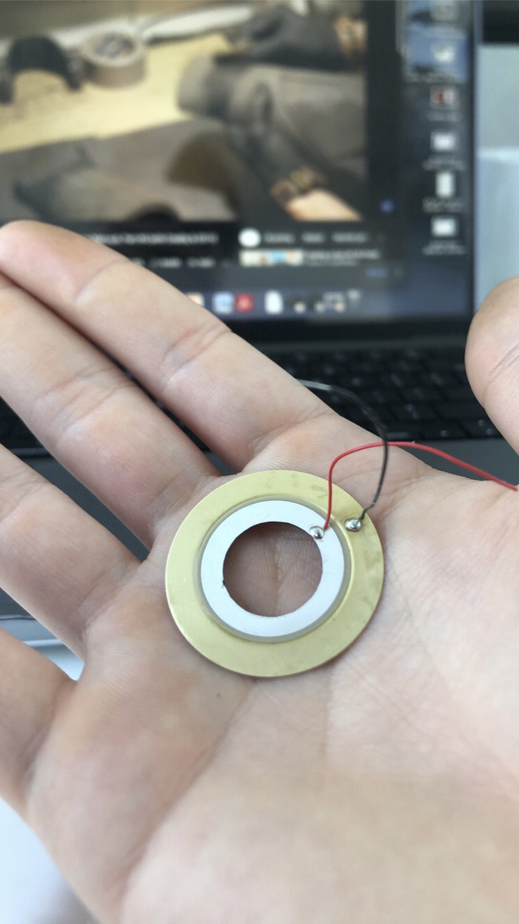
Indeed! Researched some yesterday! Angel eyes are sick and inexpensive, but unfortunately hard to find below 60mm, I was looking for something between 30 and 45 outer diameter for this end effector, as the 60mm small angel eyes are bigger than my end effector plate, and wouldn’t look so clean as well as lighting up more around than on the “nozzle”. With a custom ring ill be able to also angle the leds to my liking, so they can aim closer to the “nozzle”!
Anyways ill be keeping an eye out for them in future projects, good call!
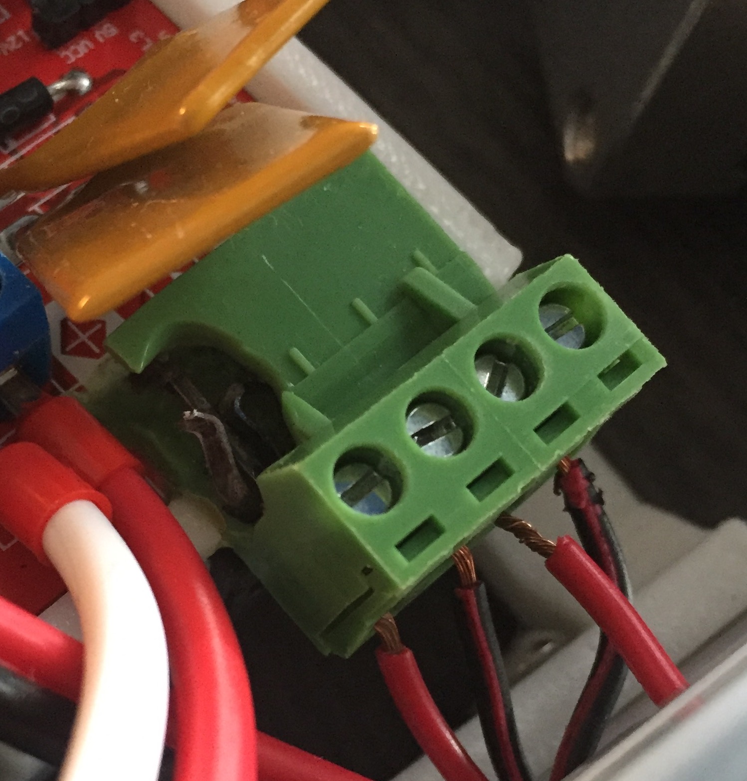
Got two of these, they seem to be within spec! 13.5A, 400V, 1.5mm2 wire.
Sorry forgot to answer that question. Those will do fine. On my board I just replace by similar connectors to those blue ones. The wire hole is not that big but any thing is better than those sliding green ones.
This is a similar example of what happened in my board.
Damn, weird they still use those connectors knowing theyre so bad…
1 Like
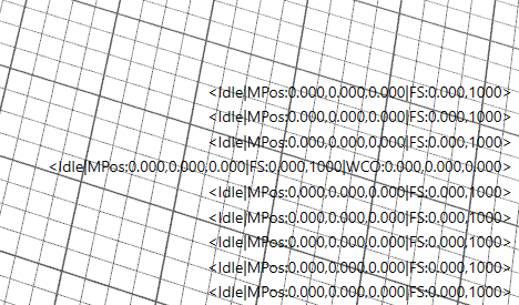
Tried the switches but I dont see anything happening, no alarm or anything in communications…hmm
EDIT1: Restarted the mega just in case but made no difference
Also the GRBL Settings arent labelled for some reason, annoying bug i assume

The non labeled grbl setting are extra setting that don’t exist in grbl. Remember most softwares are made around grbl. It’s no bug.
EDIT:about the button issue. Try this. Unplug one of the buttons and check if anything happens please.
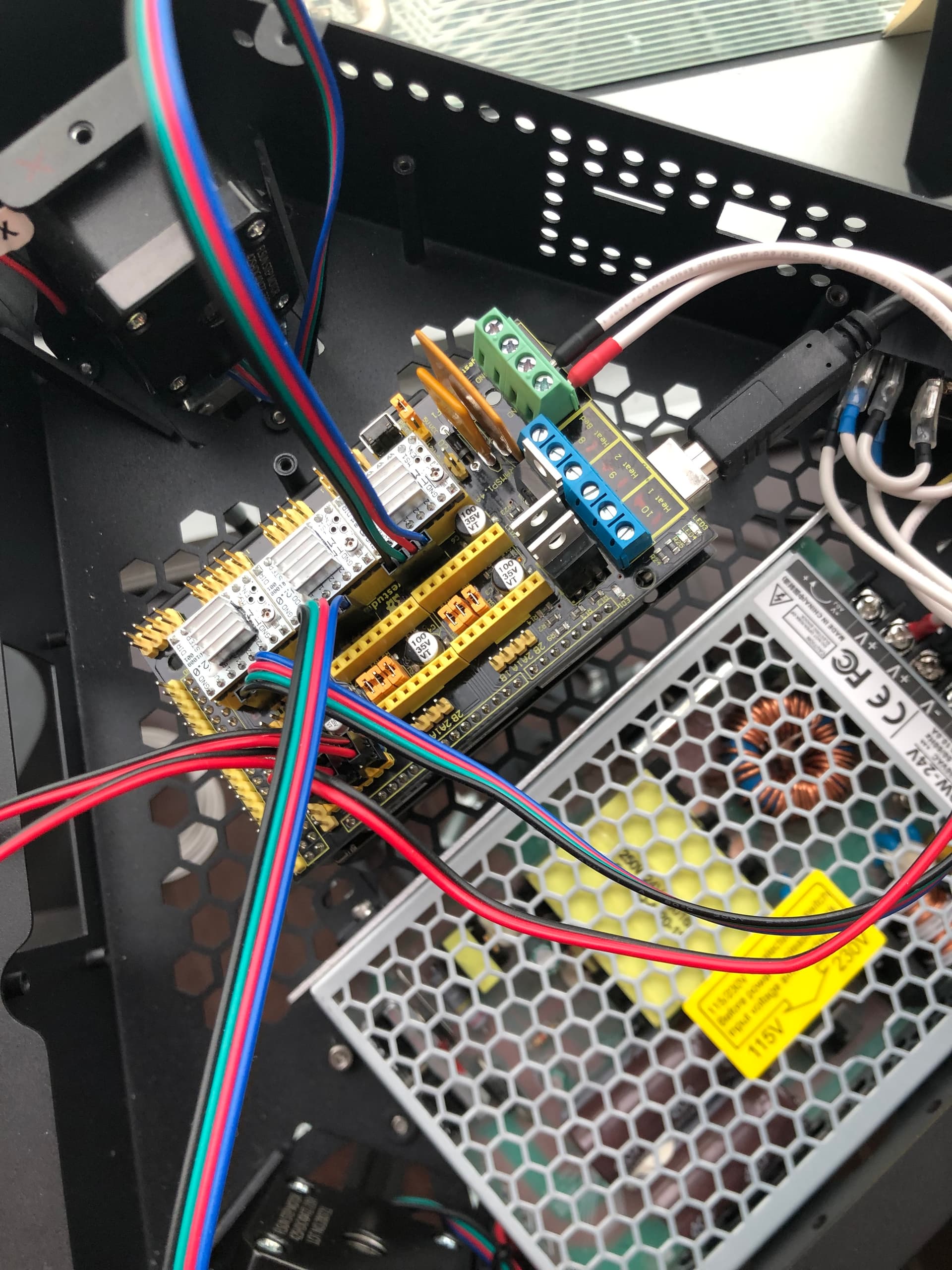
By the way. Judging by the photo I think you are powering the wrong rail.
Cant notice anything, maybe wrong wiring? but i doubt it, triple checked
Isnt that the 11A rail? Powering the closest one to the blue connectors
That one is for the bed alone. The other is for the steppers and heater.
Ah ok  changing it now
And I’m rechecking the configuration. I may have assigned the wrong limit switch pins. Let me look at this.
EDIT: Yup I messed limit X (it’s in X+ and not X-) and did not enabled pullups.
Do this:
Navigate to the source folder to uCNC/hal/boards/avr and open boardmap_ramps14.h and replace this peace of code:
//Setup limit pins
#define LIMIT_Z_BIT 3  //assigns LIMIT_Z pin
#define LIMIT_Y_BIT 1  //assigns LIMIT_Y pin
#define LIMIT_X_BIT 5  //assigns LIMIT_X pin
#define LIMIT_Z_PORT D //assigns LIMIT_Z port
#define LIMIT_Y_PORT J //assigns LIMIT_Y port
#define LIMIT_X_PORT E //assigns LIMIT_X port
#define LIMIT_Z_ISR -4 //assigns LIMIT_Z ISR
#define LIMIT_Y_ISR 1  //assigns LIMIT_Y ISR
#define LIMIT_X_ISR -6 //assigns LIMIT_X ISR

//Active limits switch weak pull-ups
//#define LIMIT_X_PULLUP
//#define LIMIT_Y_PULLUP
//#define LIMIT_Z_PULLUP
by this one
//Setup limit pins
#define LIMIT_Z_BIT 3  //assigns LIMIT_Z pin
#define LIMIT_Y_BIT 1  //assigns LIMIT_Y pin
#define LIMIT_X_BIT 4  //assigns LIMIT_X pin
#define LIMIT_Z_PORT D //assigns LIMIT_Z port
#define LIMIT_Y_PORT J //assigns LIMIT_Y port
#define LIMIT_X_PORT E //assigns LIMIT_X port
#define LIMIT_Z_ISR -4 //assigns LIMIT_Z ISR
#define LIMIT_Y_ISR 1  //assigns LIMIT_Y ISR
#define LIMIT_X_ISR -5 //assigns LIMIT_X ISR

//Active limits switch weak pull-ups
#define LIMIT_X_PULLUP
#define LIMIT_Y_PULLUP
#define LIMIT_Z_PULLUP
Just to make sure Arduino IDE does not use any cached objects close it and reopen the uCNC.ino. Recompile and upload
Changed it, saved it, need to recompile and reupload rigt?
Also tested my limit switches, i dont know if its a standard but when the buttom is pressed, the current is cut. I thought it was the opposite, where the button being clicked closed the circuit. Tested it with a nice janky led setup
EDIT1: now that I think of it, the Probe you also designed opens the circuit/cuts the current, I guess its always like that, just never noticed
go the cnc_config.h file (should be visible in your arduino IDE
change the board from
#ifndef BOARD
#define BOARD BOARD_MKS_ROBIN_NANO_V12
#endif
to
#ifndef BOARD
#define BOARD BOARD_RAMPS14
#endif
Oh…lolol. Limit X was right after all. Sorry. lolol
Go back to boardmap_ramps14.h and set that section like this
//Setup limit pins
#define LIMIT_Z_BIT 3  //assigns LIMIT_Z pin
#define LIMIT_Y_BIT 1  //assigns LIMIT_Y pin
#define LIMIT_X_BIT 5  //assigns LIMIT_X pin
#define LIMIT_Z_PORT D //assigns LIMIT_Z port
#define LIMIT_Y_PORT J //assigns LIMIT_Y port
#define LIMIT_X_PORT E //assigns LIMIT_X port
#define LIMIT_Z_ISR -4 //assigns LIMIT_Z ISR
#define LIMIT_Y_ISR 1  //assigns LIMIT_Y ISR
#define LIMIT_X_ISR -6 //assigns LIMIT_X ISR

//Active limits switch weak pull-ups
#define LIMIT_X_PULLUP
#define LIMIT_Y_PULLUP
#define LIMIT_Z_PULLUP
Changed that at the start, like you had mentioned in the guide you made!
They all work!!! 

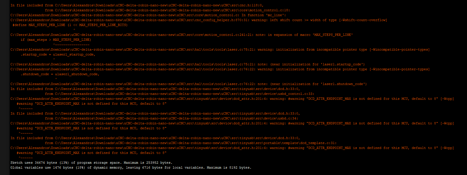
If you changed the BOARD in the config file you should be having a clean compile.
By the way you’r still using that branch delta-robin-nano-new right?
I re-did the steps I wrote above and I get a clean compile.