Got everything else but exact same voltage reg… found similar ones and I have them in hand, all 5V, im just not sure if theyd work!
L7805CV
7805CT
LM7905CT
78L15A
Looked a bit on the internet but i cant figure out if theyd work, not sure i understand all the principles of voltage regs, could you give it a quick look please?
This is quite easy. They are all regulators. 78’s are positive voltage regulators (positive rail). 79’s are negative voltage regulators (negative rails).
The second number is to what voltage they will regulate. 7805 is a positive regulator that outputs 5V. 7815 outputs 15V.
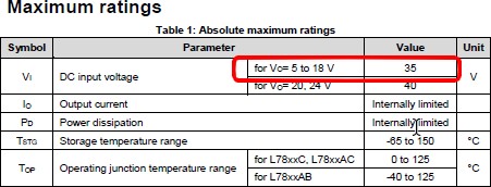
From the datasheet you can look at the maximum ratings
For example the maximum input voltage that the 78’s regulator (with outputs ranging from 5V to 18V) is 35V. So it will be able to handle 24V. (It will get a bit warm though)
The letters are mainly related to current and packaging. L78 will hold up to 1.5A the 78 will handle up to 1A the 78L will handle 0.1A (if I’m not wrong).
EDIT: By the way. The caps on your ramps are rated for 24V or more? And what about your poly fuses?
EDIT2: Check this guy’s video. It should give you all the info that you’ll need. He actually recommends just the D1 removal so you better check his video.
EDIT3: After some investigation (as I told you I never did the 24V mod just feed some drivers isolated) and seeing how other people replaced the voltage regulator on the Arduino Mega to handle 24V I must say… I do recommend the D1 and just power up the Mega from USB. I did not found a pretty solution for the voltage reg replacement. They will work…but are just ugly as hell.
Yup. By removing D1 you should be all good. This will prevent feeding the 24V into Arduino Mega. It will be need other power source like USB but it’s not a big deal. In this case you will already have the cable plugged in your PC USB so… just be aware of the initialization that Alex Kenis mentioned. I never had any problems even when I didn’t followed it by the book but you never know.
Just check the led resistors also like Alex Kenis to see if they fall into specs.
Ah yes, forgot to mention im my previous comment, resistors are 3001 so 3k ohm, in the video he says more than 1.5k is good!
Will look into the initialization!
Instead of the piezo mount you sent me, where the bowden tube runs through the middle, what about using this PCB in addition to three of these ?
The Bowden tube hole will be too narrow for any point of my end effector, so an array of 3 could work well! I saw that its possible to drill out one big piezo but it seems a bit janky hahah.
I don’t know how well these will work since I’ve never used them. I also have no idea how much pressure it will take to trigger them or how they will react to vibration. This is something you will probably have to figure out yourself if you choose to use these type of sensors.
But I guess the best approach is to take babysteps. First get to see if µCNC is able to drive the delta.
Then you can start thinking on the probing issue…by then maybe I’ll have the servo control thing solved too…or you might find a better alternative.
Just a quick note on the matter, not that is currently relevant but…after spending the last day revolving around the matter and the way to approach it, I’ve decided to integrate servo dedicated pins to the µCNC core. Since this comes with modifications to the MCU interface that bridges the MCU hardware abstraction layer from the CNC core code I’m putting the other core branches aside to deal with this first. I’ll also add one or two extra functions that will probably come in handy to add other modules (like low speed software based serial communication that will open the door to include trinamic drivers configuration, etc…)
EDIT: I’ve implemented SERVO pin types into µCNC (It will support up to 8 configurable servo type pins). Currently I’ve only done this for AVR. I’ll extend this to the already developed µCNC cores. After that I will hack the probing section of the code to make it modifiable in a modular way. After that the module for a bltouch (or any other kind of probe that is controlled with a servo) is one step away.
EDIT 2: I believe I’ve implemented SERVO pin types on STM32 and SAMD21 cores. Next will be testing and integration. After that add a couple of hook’s to the probing motion to allow adding external modules…
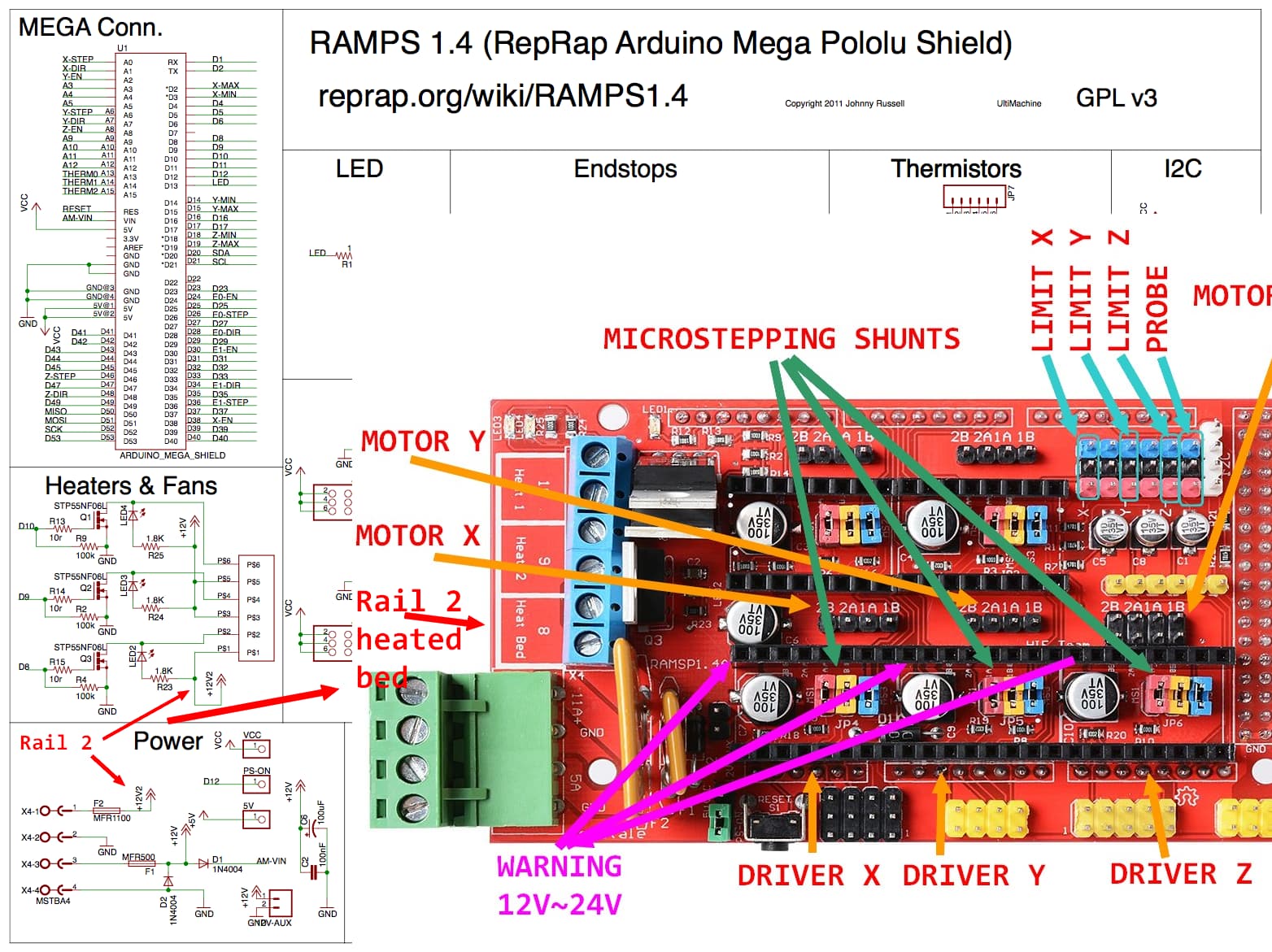
Btw, I’m doing the PSU to RAMPS1.4 wiring tonight, have seen some different configurations and not sure which one is best, any preferred one in particular? Or is it specific to my PSU?
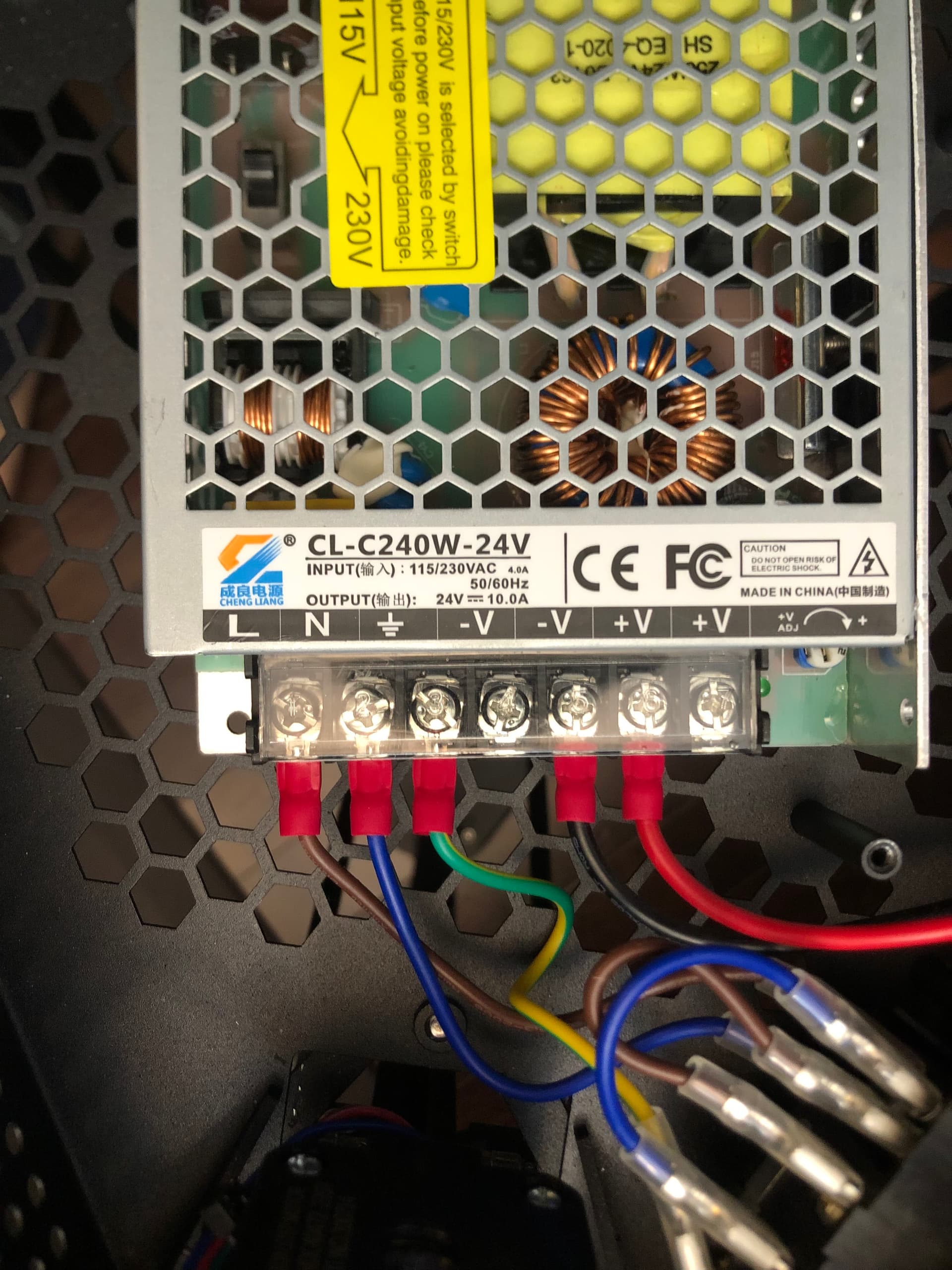
Ok with your edit I see what your saying. IMHO those are both wrong. Those shunts on the PSU are useless. Those rails are common I believe (You must check your PSU how many rails it has…those type of PSU usually have only one), that means that internally they are already interconnected.
You don’t gain anything from that. If your worried about the voltage drop on the wires you should connect 3 wires to your board. Connecting like that is like trying to make the same water that flows through 2 pipes to run in only one…it won’t.
For your application and if I understood right you’ll be only powering the stepper drivers so this is more then enough.
The shunt on the RAMPS socket side that is just feed the 24V in both RAMPS rails. If you are only connecting a wire to the RAMPS then yes you can do that…but again you will only need to power the rail were the stepper drivers and the hothend is feed. The other rail is dedicated to the hotbed.
By the way testing is done and servo signal is working. The thing remaining is to mod probe a bit to allow the integration of modules. Later a dedicated bltouch module will be implemented.
This week I’ll have to run down the code from top to bottom because the UNO is getting tiny . I’m adding a bunch of new stuff (PID controllers, servo output pins, s-curve acceleration, and the stm32f4 core) to release next version 1.4.
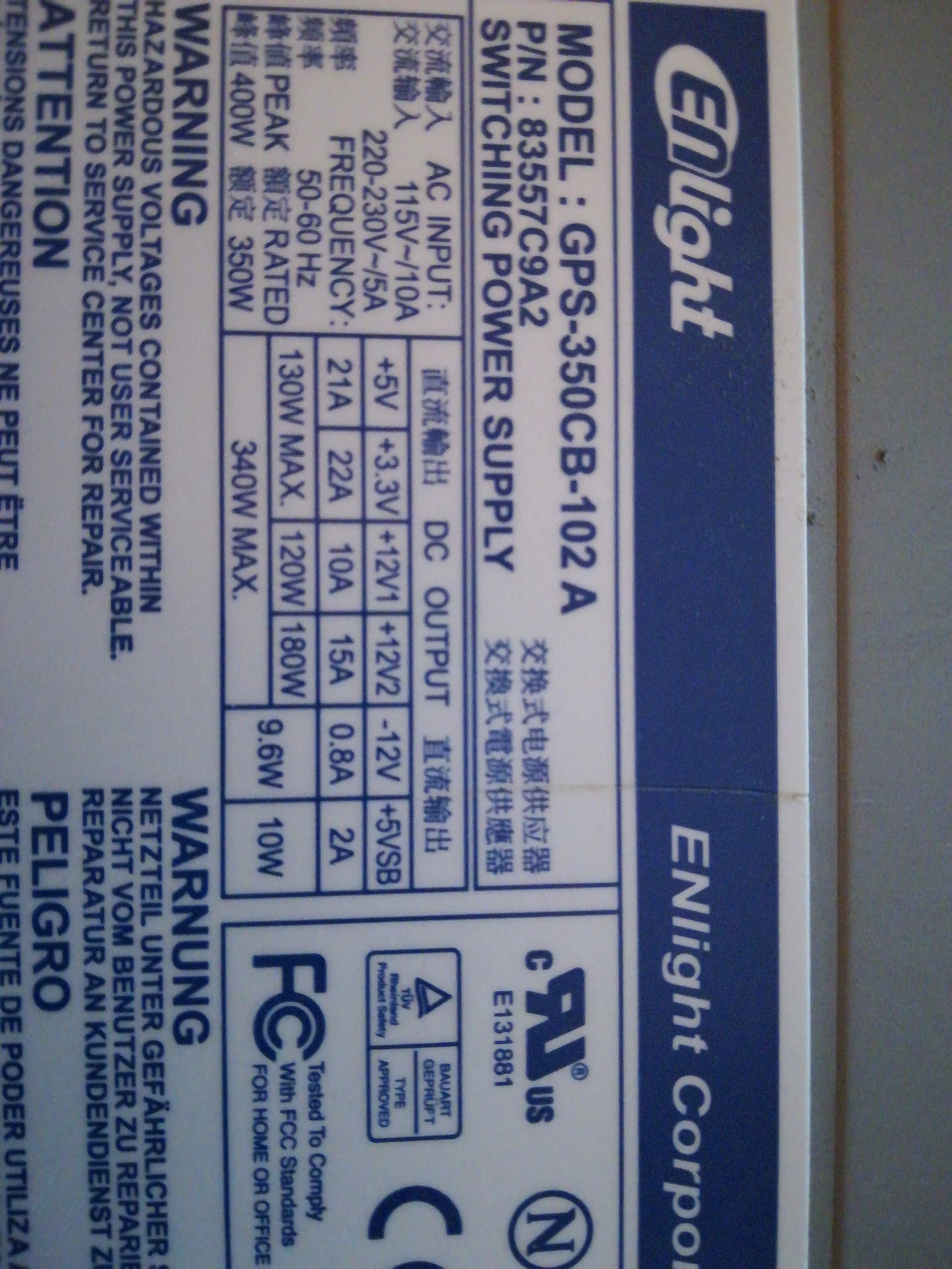
I see what you’re saying, Ill check the exact psu model once im back, it looks pretty generic. Ill make sure to see how many rails it has!
I wasnt really thinking about voltage drop tbh…but good point
How would I connect 3 wires? ground wire???
Anyways, wont be using a heated bed not a stepper motor on the end effector, but I’ll be using a dc motor, ± 6V, much like a cnc spindle! I was also thinking of using some Leds on the end effector, found the lovely neopixel rings but from what I understand neopixels are a bit of a pickle to use in these cases. I don’t need any fancy rgb,just want a worksurface from the end-effector, so a white ring light that uses two contacts would also work np if neopixels cant be integrated!
Or some lilypads mounted in a ring formation. The flagrant aspect of the build is yet to come and not so important right now, just wanted to let you know what im planning!
So no heatbed and 3 steppers only, plus a 6V DC motor and some led lights to illuminate the end effector, plus a probe, whatever that will be! Would be great if everything was driven by the mega/ramps and didn’t need to add extra arduinos in there…lol. Lmk if i need any special wiring with this setup
You’re writing much faster than im assembling… I need to get up to speed
I managed to lasercut a piezo at work though! No necessary rn but this way I might be able to make a “nozzle” probe, concentric to the endeffector, when the time comes…! Ill add a photo soon, saw some guy drilling the piezo out to do the same thing, tried drilling, looked terrible, lasercut is clean af, need to test if the piezo works tho hahah, ill add a photo soon
This was actually a very unfortunate expression I chose. The voltage drop is not the problem. It’s just ohm’s law. It’s a consequence of trying the pass to much current through under dimensioned wire. The problem is the power inefficiency and risk of fire through overheating wires. See Electroboom’s video and you will understand this.
Your PSU is single rail I believe. PC PSU have 2 rails identified by 12V1 and 12V2. (the se are 2 independent 12v outputs)
As for the 6V spindle what the power ratting on that?
If is a small motor I guess you could use the hedbead transistor to control it directly with PWM ??? That means that your RAMPS would have one rail powered at 24V and the other at 6V. EDIT: That is if you only are going to run that in one direction. If you need to run it in reverse you Will need a driver for that. EDIT2: It’s also possible to configure the spindle pwm Pin to other pwm capaple Pin on the board and connected to an external driver just by customizing the board map file .
The Neopixel ring uses a very specific 800KHz pwm protocol. There is a library for Arduino UNO. µCNC does not support this natively but I guess an extension module is possible.
Ohh I see, yes ofc, I’ve made sure to use 1.5mm2 wire, properly crimping it at the end etc. dw I wont try to power the psu with some 30awg wire lol
Made some PC cables last year and was trying to figure out how to get the thinnest crosssection wire without burning everything, almost went down to 22awg but decided It wasnt worth the risk.
Noted for the psu rails, so just two wires to the 11A inlet of the ramps would be good right?
No need for two directions on the spindle, it will translate to linear motion anyways!
Power rating as in amps? If so no clue, will need to ask the manufacturer, 0 documentation on the motor…
Is it possible to do the 24v and 6v rails thing?
Forget the neopixel then, id rather make my own ring light anyways so ill go with these mounted on a 3d printed ring basically, this way it will be exactly as i want it to be
EDIT 1: Planning to add a small peristaltic pump too actually
Man it sound’s like your building a torture device or something
So let’s see…
If you account for the 3 stepper drivers you’ll be powering up (that will draw no more than 1 to 1.2A each and not all the time) you can see that your safe.
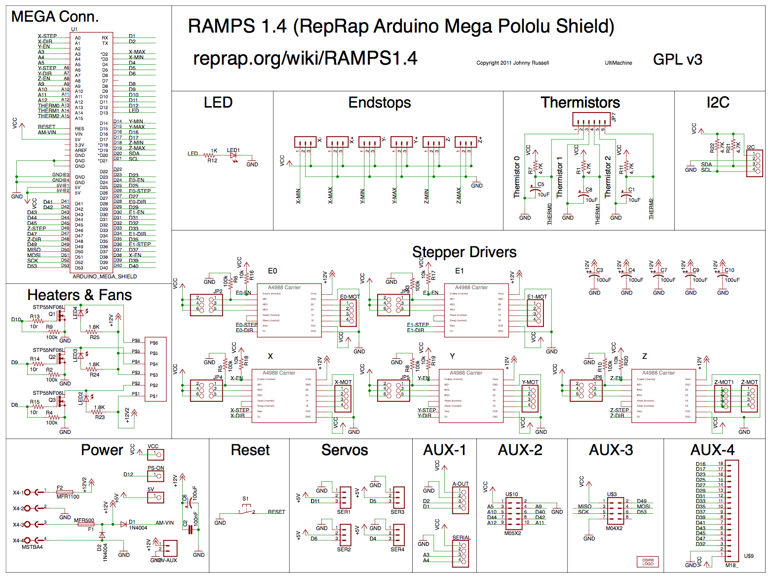
EDIT: from that same schematic you can also see that the rest of the board is powered by the 12V rail (rail 1). That is the steppers and the heaters 1 and 2.
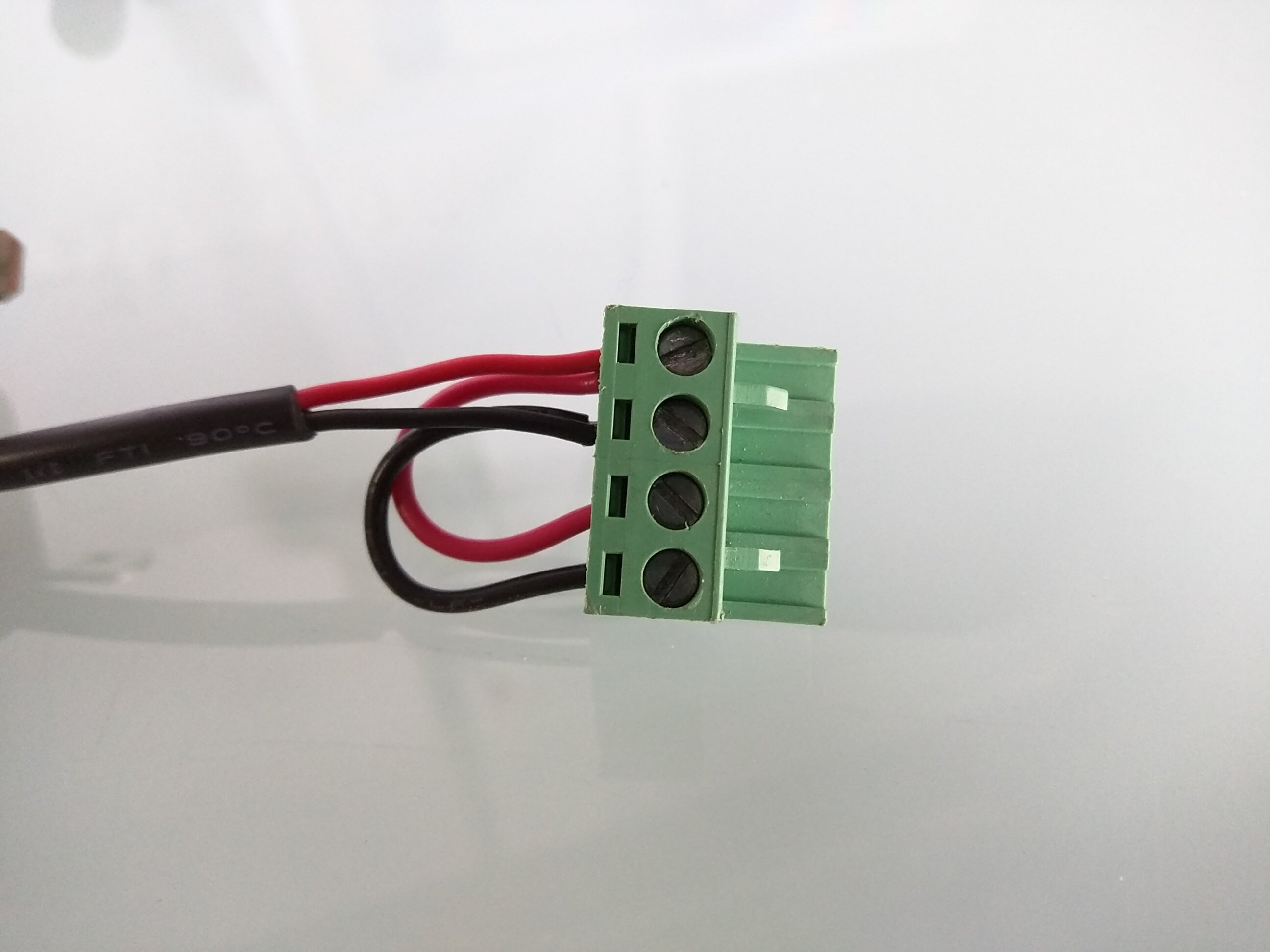
By the way just an advice if in the future you plan to reuse this board on a 3D printer. Replace that green power connector you see in the picture by a better one. That slide connection is pretty crappy and is one of the main causes of fires on these boards. For your current application is just fine since this is all low current stuff. Mine melted and almost got on fire good thing I noticed on time.
EDIT2:By the way in what type of laser/power did you cut your piezzo discs?
ok cool i see, which means that it will be limited to 6V/or ranging from 4 to 7V lets say through software? or do i need to change some components?
any info on which one? saw that it can cause a mess on some other posts…
itd be good to change it now and forget about it
150W KERN Optiflex CO2 laser, obviously at work as that machine is about as big as my room, without considering the cost…loool. Cut it at about 80% power, 0.7in/sec, fast and easy, centering it was the hardest part. If you’re interested and dont have access to a similar machine I can send you a couple least i could do!
It’s the same thing with the 3D printed. What the firmware does (Grbl, Marlin, µCNC, whatever…) does is send a PWM signal to that power transistor. A PWM is nothing more than a square wave signal with a duty-cycle %timeON-%timeOFF. It’s like flicking a switch on and off several times per second. On average (the motor, heater, etc…) your load will “feel” an equivalent voltage/current that is proportional to that duty-cycle. In the case of 3D printers there is other stuff going on as well since there is a feedback signal (measured temperature) and a PID controller (proportional integral derivative) adjusts that PWM automatically so it will keep the temp steady…in a simplistic way of putting things.
Again Electroboom is your friend and makes you laugh
EDIT: I just realize I kind of made the the answer unnecessarily complicated .
Power the rail with 6V and the software can adjust the output from 0V to 6V in a even more simplistic way…Again remember this is on average.
I’ve had good luck finding 12V dumb LEDs (in ring format or not) by looking at auto parts. They make a few in different sizes and styles. Same with lighted switches.


 ground wire???