Thank you! Ill let you know once im back on it but i think you’ll be alseep by then 
The idea is to use a Grbl compatible firmware (that can run a Delta machine) and a software tool for Grbl with surface mapping capabilities to do the work.
Lol… probably. I’m GMT-0 time zone. I’ll try to leave you a gideline before that.
1 Like
Thank you! Yeah here im “GMT -5”, Toronto. Ill look for a guide to migrate everything from the MRK to the MEGA as well, I guess it would be rather straight forward but best not to risk it!
1 Like
I’m in @Paciente8159 -7 in the winter. That’s how I will describe it from now on.
2 Likes
That would make this all very easy if it existed. I wonder if examples are available… seems like a whole lot of floating point math to just toss on top of grbl. I’d like to see how if anyone finds it.
LOL
That’s what we are trying to see if it can be accomplished ![]()
Now for uploading µCNC:
DO NOT POWER YOUR PRINTER…
Just connect the USB cable. It’s enough to power the Mega board and program it.
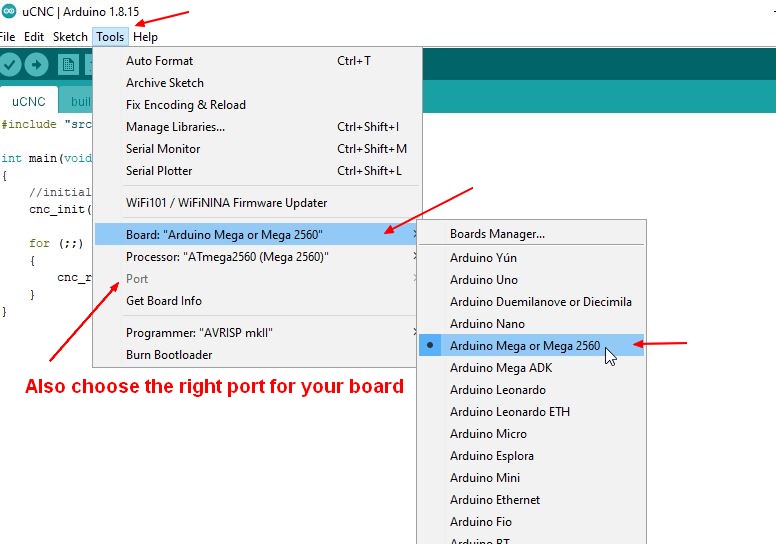
Install Arduino IDE. Go to µCNC github page download the code from the delta robin nano branch and unzip it
Go to the folder with the contents and enter folder uCNC.
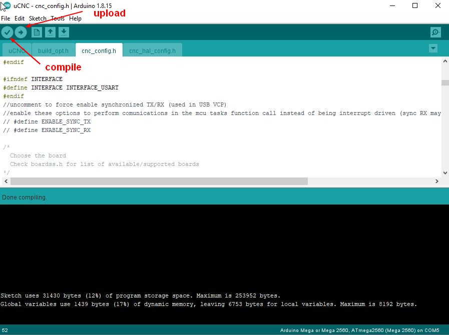
You will find a uCNC.ino file there. Open it with Arduino IDE.
Then follow this…

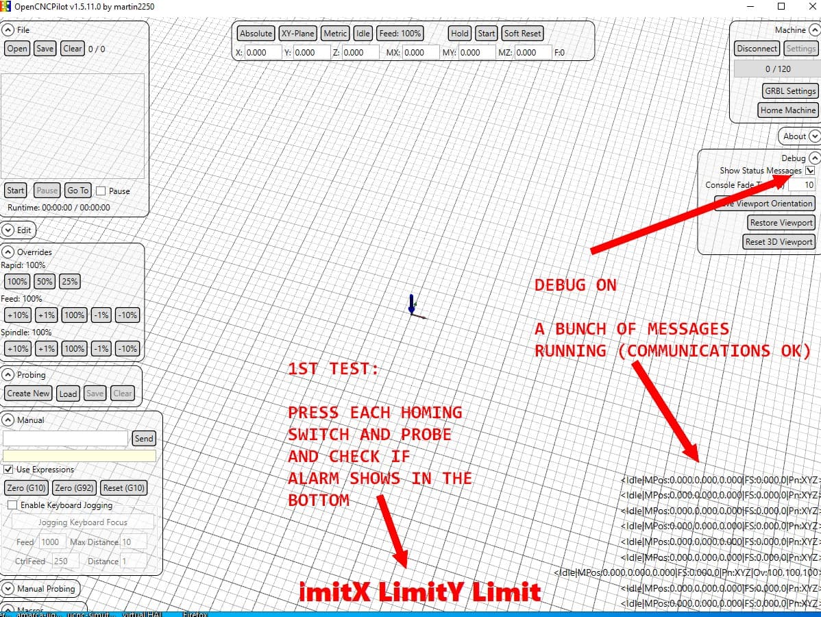
If everything went well and you open OpenCNCPilot to connect to your Mega COM port communications should start…
1 Like
Amazing, thank you thank you thank you!!!
Ill work on it as soon as im back and let you know how it went 
Now for OpenCNCPilot. This will be a multi part explanation. Several things must be taken in account.
First test your switches:
Next settings
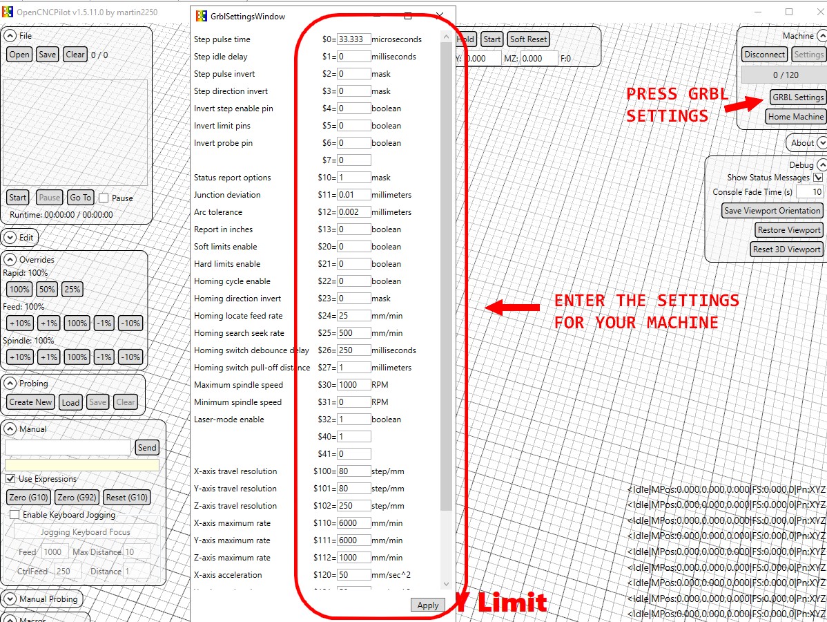
First all settings are in mm. Be aware of that.
First you need to know the steps per mm of your tower steppers.
You should enter them in $100, $101 and $102. I believe they should all match.
Also all motor speeds should match ($110, $111 and $112). This is an alpha test. be conservative I would not go beyond 400~500mm/min.
Accelerations the same. All should match. Again be conservative. 1~5mm^2/s will give you a slow speed increase.
Then you need to know 2 distances ($106 and $107). Check the image.

After this unplug your usb cable…replug it and power on your machine.
ADVICE. Power the machine with an extension cord with an on/off switch. This will be your safety measure in case a motor or the effector starts to go crashing somewhere .
now the first thing you need to check is if everything is going in the right direction.
Send a G0Z1 command to your machine. All 3 motors must go up. if they are not (all are going down or they are going in different directions that needs to be fixed). Several ways to do that.
to be continued…
CONTINUED
So after you sent G0Z1 several things could have happen…lets walk through them:
- Some or all motors moved down and not up. Setting $3 can help you with that. Each motor has a bit assigned. X is bit 0, Y is 1 (binary mask), etc…You can think like this…the values for each motor are X=1(mask 0001), Y=2 (mask 0010) and Z=4 (mask 0100). If you want to invert one, two or all 3 motors just add their values. For example: invert X and Z (1+4=5 = mask 101). All 3 motors is 7 (1+2+4). You get the idea. So set $3=5 and X and Z are inverted. Another way to do this without settings is to simply power off yout board (ALLWAYS POWER OFF) and flip 180º the motor header connection in your RAMPS board.
- One or more motors moved more/less then the other. Check you entered the right settings to all 3 motors. Check also that all motors have the same shunt configuration on your board.
- None of the motors moved. Check your connections again. This one is kind of stupid but $4 has no effect on µCNC because I hardwired it to work in negated logic like most drivers work. Easy fix for next release and I will do it. This should not happen. But you never know.
If you managed to get all 3 motors running the same distance and up lets keep going.
Next for the homing stage.
Turn on homing cycle and enable hard limits. this is done by setting $22 and $21 to 1.
Modify your home searching rate to something slow ($25). I’d recommend 100mm/min. It’s super slow but safe. Disable pull-off distance by setting $27=0. This is a feature that makes cartesian machines pull-off by that amount on all axis. Later I will change this to make pull-of only on Z for Delta machines.
µCNC starts homing towards negative distances. You will want the delta to home up so also invert homing direction by setting $23=7 (inverts all 3 motors).
At this stage power off and on again (don’t forget to unplug USB). At the next power up µCNC will be locked down. To move it it expects either an Unlock command or a homing.
Press homing and keep that button of the power cord on your hand just in case.
VERY IMPORTANT: PLEASE CHECK THAT EACH MOTOR LIMIT SWITCH IS PAIRED WITH THE RIGHT MOTOR. MOTOR-X AND LIMIT-X MUST BE IN THE SAME TOWER. AND SO FOR ALL THE OTHERS. IF NOT THEY WILL TRY TO KEEP GOING UP DESPITE HITING THE LIMIT SWITCH.
VERY IMPORTANT2: I DID NOT IMPLEMENT ANY RESTRICTION GEOMETRICS FOR THE DELTA. ALWAYS BE NEAR YOUR MACHINE WHILE USING THIS VERSION OF THE FIRMWARE. There are restrictions/limits to the angles the arms can perform relative to the effector (for example preventing going beyond the boundaries of the machine). I just had time to implement the basic kinematics to make it move. There are no constrains check.
I think that’s it… any question just post here. I’ll reply as soon as I can.
1 Like
Ok. Replying and bookmarking for later. To soon for me to take all this in, but I would love to visit this, this summer.
1 Like
Back on it for a minute!
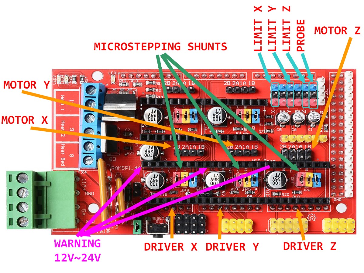
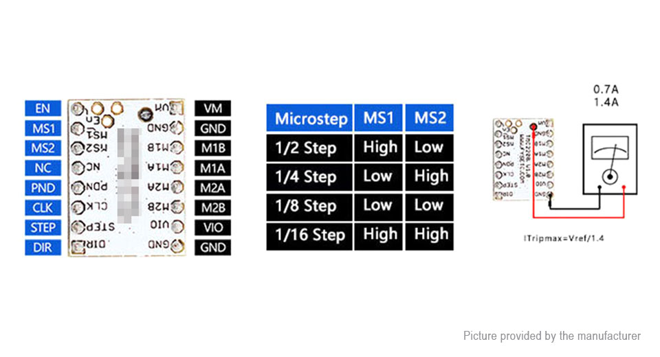
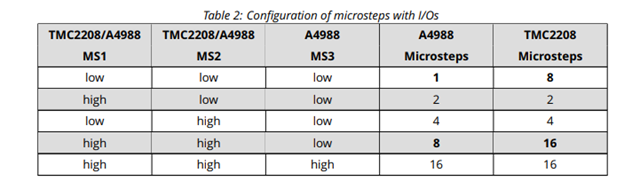
I was wondering, before mounting the stepper drivers, how much micro-stepping should I set up?
EDIT 1: If it matters, on the MKR board all three shunts for every driver were on.
You can go with the full 1/16th microstepping (that is all shunts on). TMC2208 will do some interpolation microstepping of it’s own. I usually use any value from 1/4th to 1/16th. 1/4th will give me more torque but noisier steppers and less resolution. So just use the same configuration. It will do fine.
Edit: just for reference I think (depends on the drivers and motors of course) but as a general rule you loose about 30% of torque with each microstepping factor you introduce.
1 Like
Drivers, motors and endstops installed as well as z probe!
Everything except for power, my printers power supply is 24V…looking into videos of how to deal with a possible conversion of RAMPS 1.4 to 24V
EDIT1:
Should I:
- Just cut the D1 diode on the RAMPS board since the Arduino will be running off of the Serial port no matter what and add new fuses to the ramps to handle the 24V
- Keep the D1 diode and replace the voltage regulator on the MEGA to handle 24V to a L78S05
Both conversions are quite easy, wondering if one is better than the other
1 Like
Replacing de voltage reg Will leave you the option of running marlin (if you latter reuse this board for a 3d printer) with a LCD controller and print from sd card. From that point of view this option is more flexible. For ths case it won’t matter because uCNC Will be comunicating via USB.
If you don’t mind the component replacement operation and can get locally go for it. I myself have a third option on mine. I reverted the motor voltage Pins on the drivers I run on higher voltages. I have RAMPS running the heated bed and extruder and z azis @12v and X and y @ 24v.
1 Like
Yeah it seems I can easily source the parts and the swap is within my soldering skills!
The third option is interesting but I assume it wouldnt really make sense in my case since Im running delta kinematics!
Ill be back once the swap is done
1 Like
By the way…something that just came to my mind… Are planning to use the bltouch as your probe or a more simple probe?
It just occurred to me that in the first post you mentioned the bltouch. If that is the case I will need to think ahead for an additional firmware modification since the bltouch requires a servo signal to down/stow the tip for probing and currently µCNC does not have a proper servo signal. It’s prepared to control 16PWM outputs that will work @1KHz rate.
If I’m not mistaken servo requires a 50Hz “like” PWM signal and this will require me to add additional modifications to the firmware to be able to support it.
Just let me know so I know if I have to address this issue now or is something I can tackle later.
EDIT: By the way (although I never picked up on improving my design) this kind of printable renishaw probe might be a viable alternative (also depending on the precision your trying to achieve) and all most all parts (don’t know about the magnets) can be found in the local hardware shop.
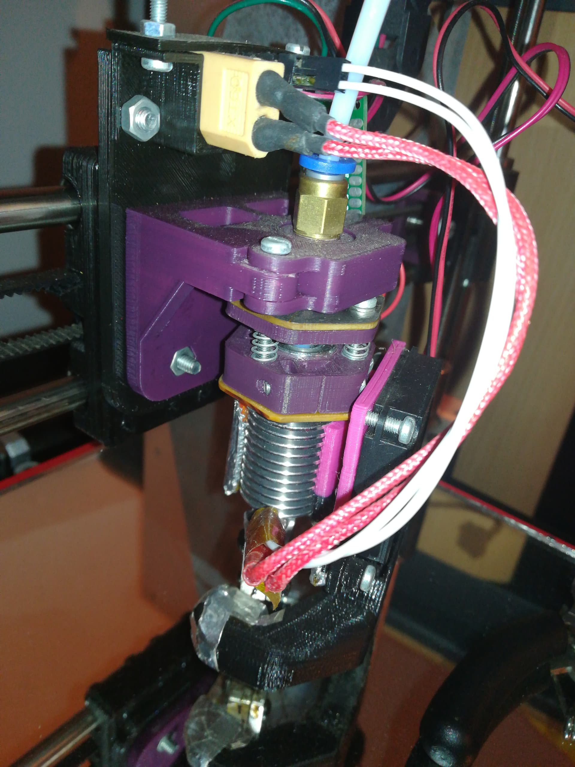
EDIT2: On my 3d printer I have a different implementation of the same concept but to use the hotend as a probe itself.
Here is a picture.
1 Like
Indeed initially it was going to be a BLTouch but I sent it back, because I figured it would be more complex to make it work with µCNC.
My main reason for the BLTouch was the actuation force is extremely low, so much so I could not find any data on it and just had to buy it to find out for myself!
The “nozzle” will be plastic, more info on that down the line  If its a circuit closing the nozzle probe idea wouldnt work, if its a piezo it could, but Im not a fan of the idea because of design complication with my eventual endeffector! Although it does have its pros and cons, any opinions on them? Could a piezo probe be used in µCNC with my current hardware? Asking bc as far as I know they dont act like switches and need some calibrating, and I read theyre snsitive to vibrations too so idk. But probing with the nozzle is really cool and easy (theoretically )
https://pyroballpcbs.com/ make a cool little pcb for them! give it a look and lmk
I like your design of the probe and though that something of the sort would work well, Id ass a calibration screw or smth of the sort to lower the pressure needed to actuate it, but I like how easy it is to make and love how the internals look.
Just looked at the picture better and seems like you could have a piezo, not sure tho lmk!
In case other probes are not sensitive enough ill go back to the BLTouch and let you know! If I havent mentioned before the build surface will be skin so sensitivity is key not to distort it!
EDIT 1: The piezo idea is actually really cool…I had even gathered the components but let it go because it seemed difficult to implement
1 Like
The piezzo sensor should work the same as a switch. Callibration hassle is done in the electronics of the sensor I believe. I’ll take a better look. µCNC Will work with anything acting like a switch. Bltouch problem is that it has an extra line that needs a sinal to control the Pin up and down.
EDIT2: Has I thought the piezzo sensor you sent is something similar to this one, although the one I just sent you should be more precise due to the diferential input measurement and insensitive to vibrations also.
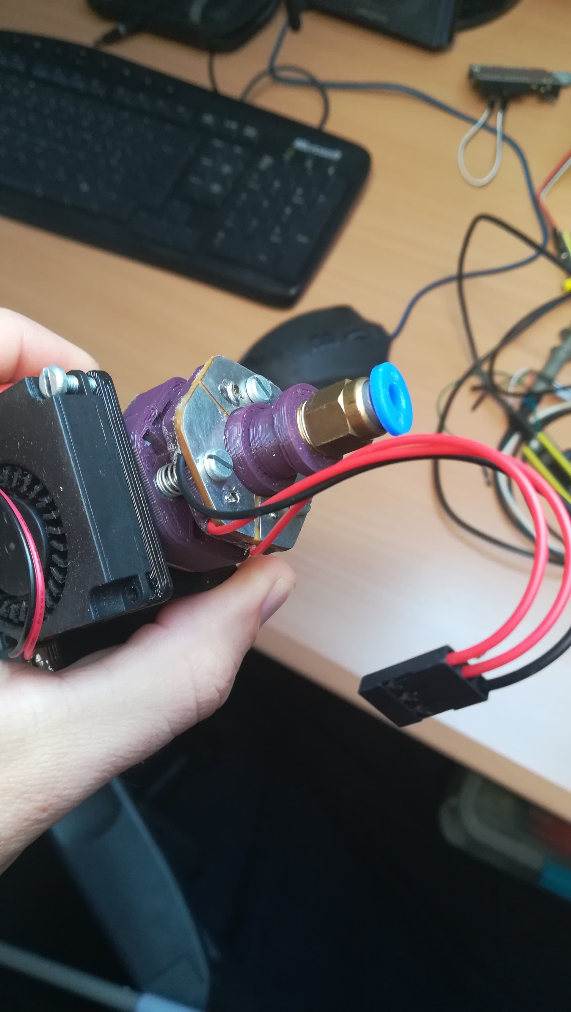
No my nozzle doesn’t have a piezzo sensor. It’s actually a mecanical switch that is closed in 3 points. I can send you pictures of it later… But it’s too stiff for your application.
EDIT: and here are the pics. Let me explain
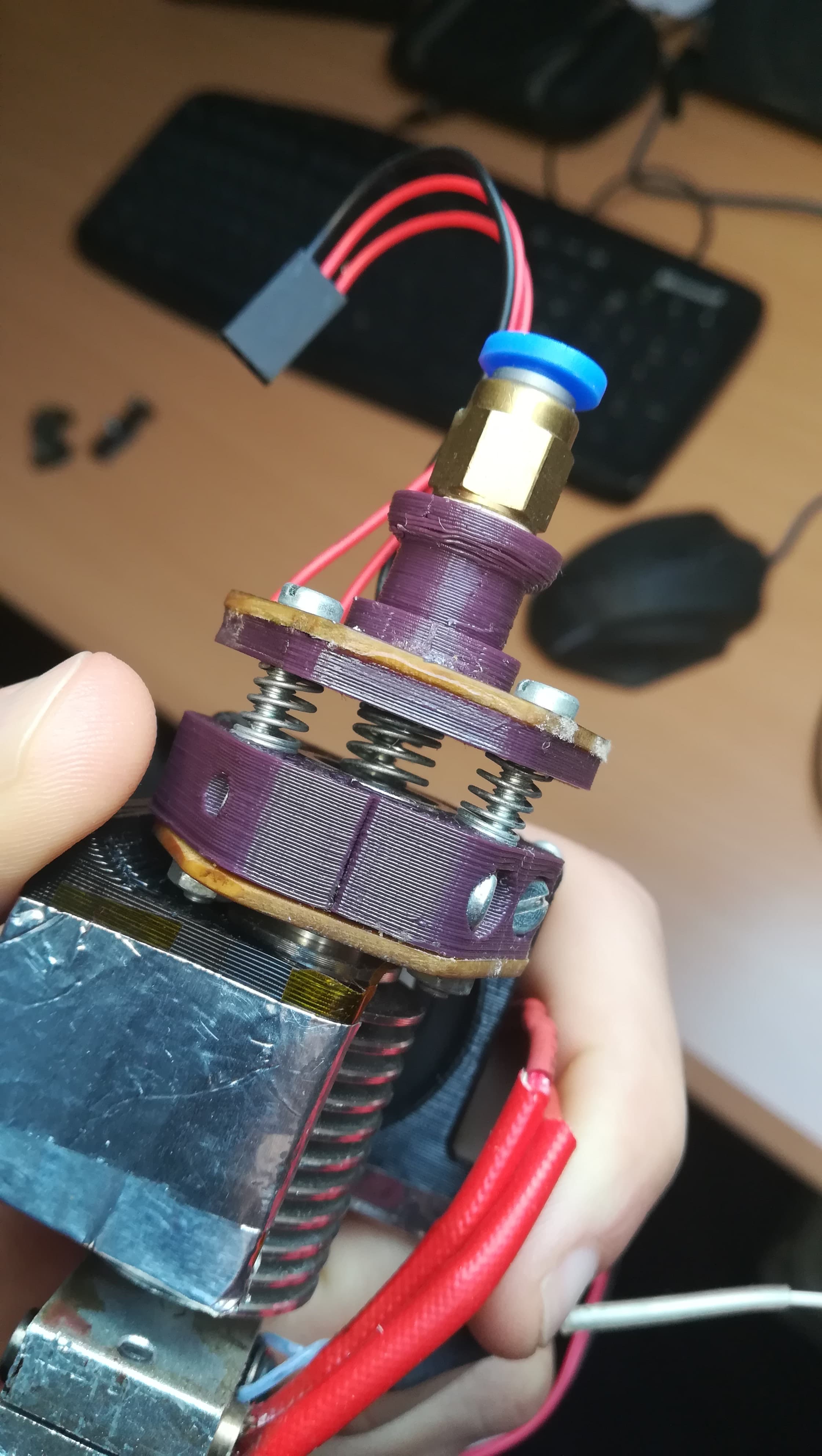
This is the top contact plate. It has 3 cuts isolating 1/3rd of the hexagon for each screw. The 3 wires (red-red-black) are soldered to each contact zone.
This is the bottom contact plate. Although it shows that it’s cut its actually a single contact surface (it’s soldered-I just used that PCB from an other top place and shunted the 3 parts). The nuts are tight against this plate connecting the 3 screws eletrically. You can’t see but there are counter nuts on the other side to keep the contact.
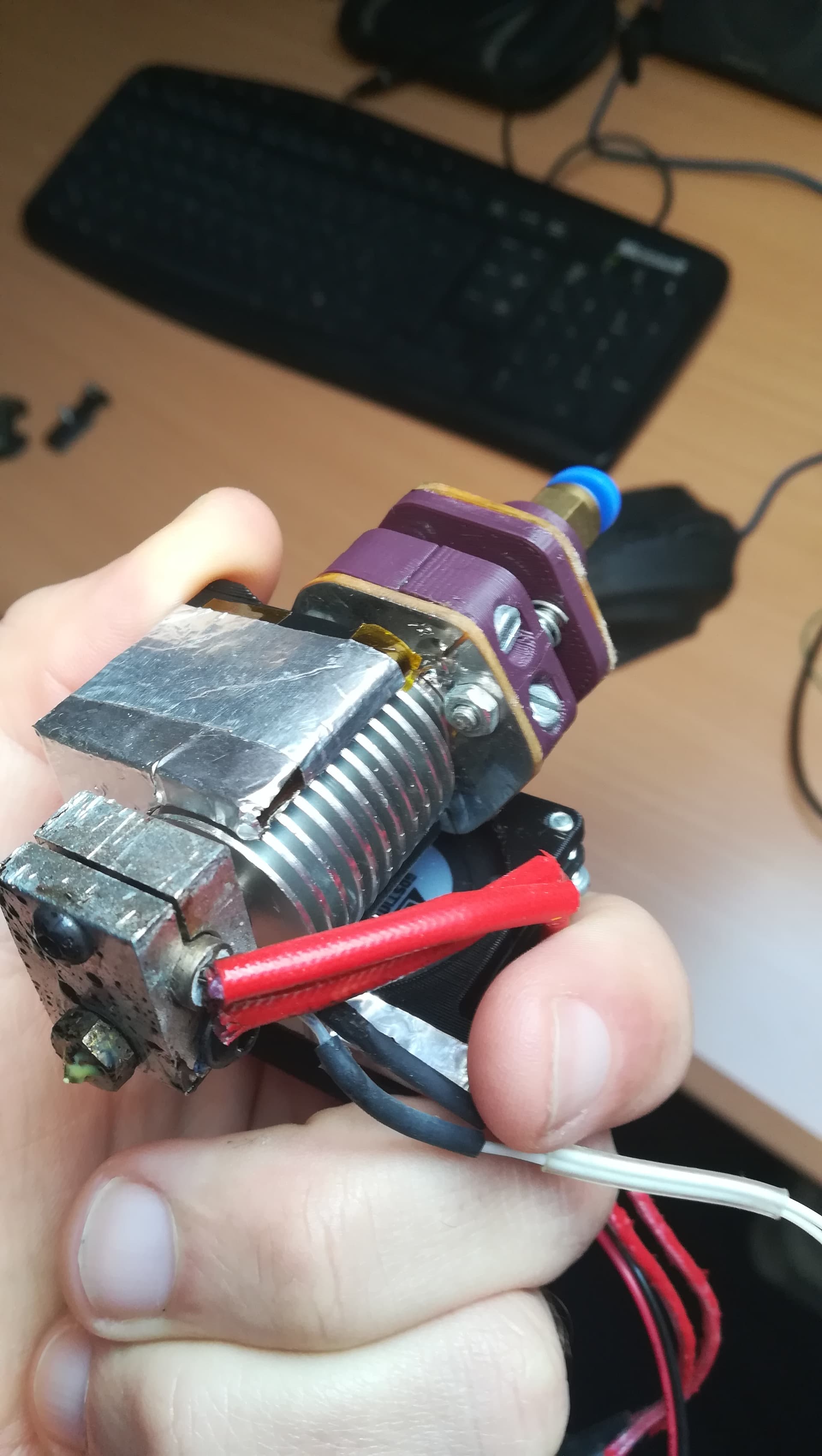
The springs force the top plate against the head of the screws, closing the contact.
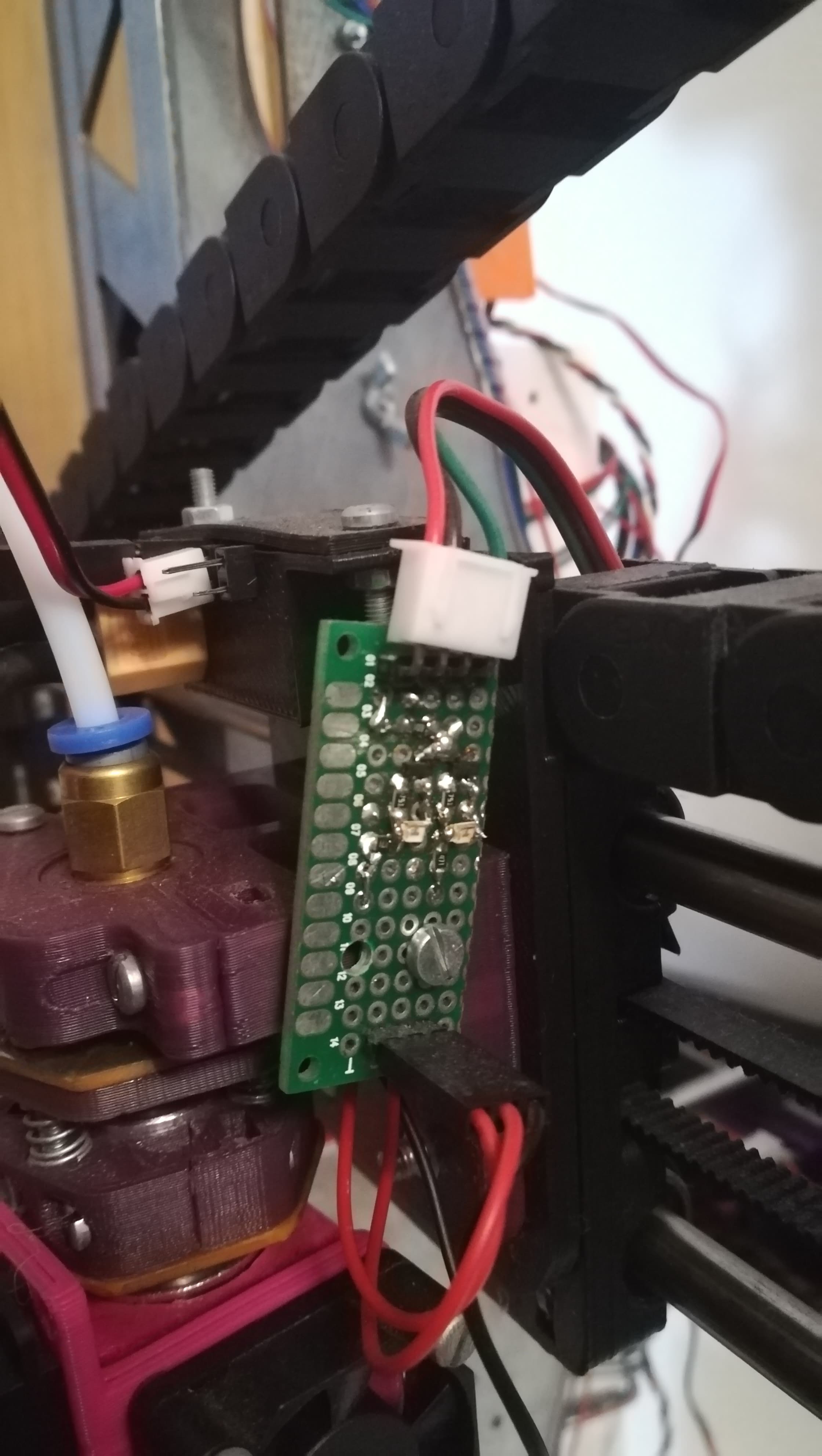
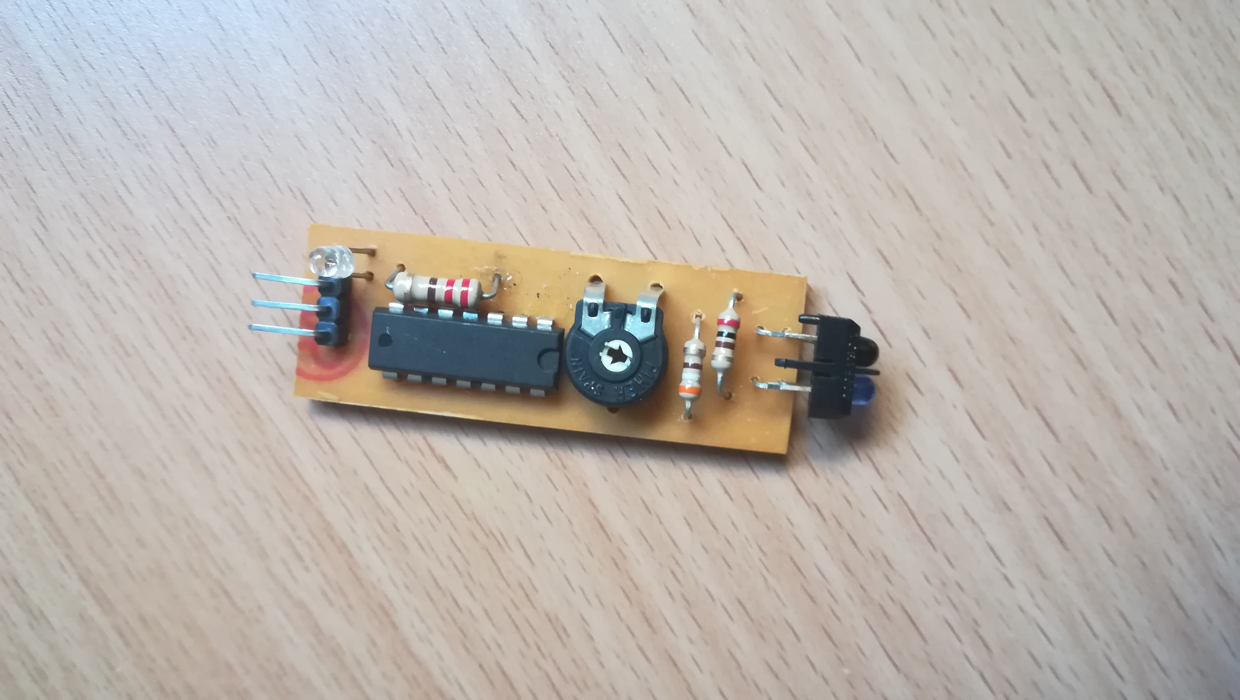
And this is the circuit board. Kind of hard to see but it’s basically 2 transistors, 2 leds and a few resistors (all smd). The transistors act like a AND or OR gate (I don’t recall what I did exactly). Each led gives me the info of wich contact is open. One led is contact 1, the other contact 2 and both is the common (GND) contact that is trigggered. This is then connected to the normal switch pins of the RAMPS.
This was my 3rd iteration at this hotend-as-probe kind of system. It’s far from perfect but it has stick around for a few years on my printer now. It allows me to swap a hotend in about 30 seconds or so.
My 3d printed renishaw probe (the one on Thingyverse) on the other hand was very sensitive. Those magnets made a really weak force at the distance they are… But they are not tunable so may also not be suited for your application.
If you want to scan something so soft as skin maybe you should use an optical IR probe like this one like David Crocker did. It Will not tou h your target and Will work on most surfaces including skin I believe.
I made one my self based on this principle of differential sensor voltage…(I’ll try to find it and send you pictures later) but I Don’t know if the precision Will meet your specs.
EDIT: Again here are the pics
Version 1 (without differential reading) - this repeatability on this was quite crappy to say the least.
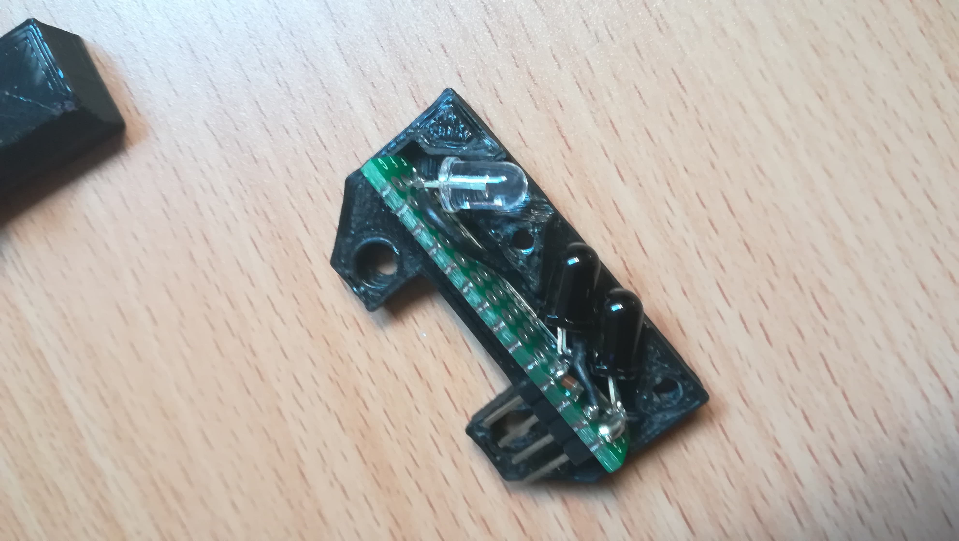
Version 2 (with differential reading) - after reading about David’s probe i did a take on my own.
this is IR LED and the 2 IR sensors that where monted near the hotend. repeatability was alot better but still it could fail by a few tenths of mm and screw layer adhesion. Propably because of the type of led and diodes used that have a wider angle of detection.
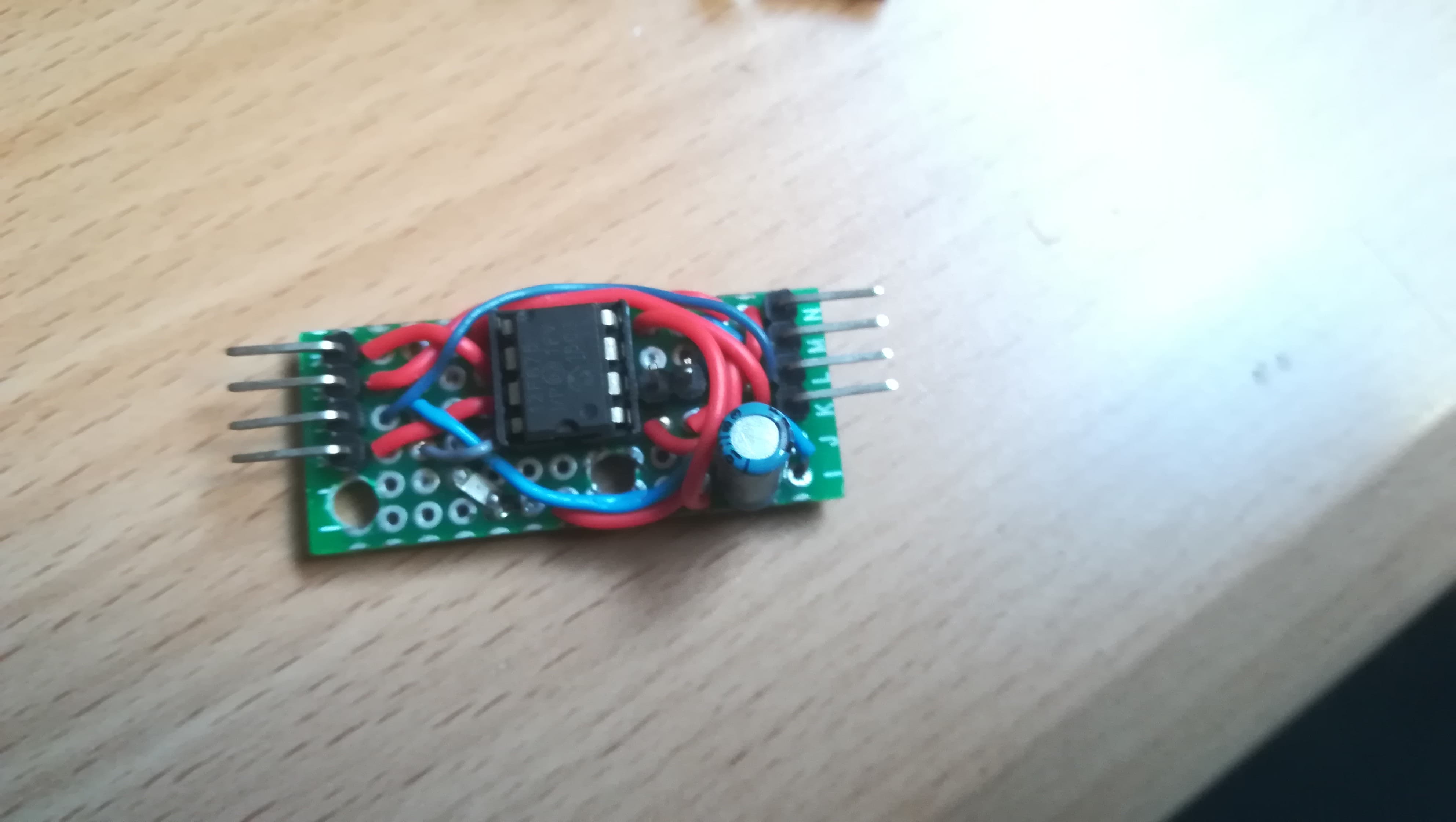
Then they would connect to this board with a PIC12F675 that I programmed with a firmware of my own to detect the levels on the sensors and send the switch signal to the RAMPS.
EDIT3: Man this response is getting long . If you don’t find a suitable solution I still have a couple of concepts in my head that you can build yourself to try and make a really light probe. If it comes to that I can discuss these ideas with you.
In the mean time I’m already thinking on how to had servo support for µCNC. I’m currently extending the cores for STM32F4 and ESP8266 in parallel, but I guess I can put those aside for a bit to add that feature.
1 Like