I want to be able to mill a 8’x2’x8" stock.
What should be the best and easiest way to modify LR4?
Is it just a matter of increasing the height of lead screws or is there more parts modification?
I am building a foil board out of eps foam so it doesn’t need to have a ton of rigidity or precision but would be nice to have for other projects
A LowRider is most rigid when the router (gantry) is closest to the work piece. As Z increases, te lever arm working against the mechanical system gets much longer and thus rigidity decreases significantly as Z height goes up.
If you’re wanting to do planar operations on your material (e.g. facing thick stock), then the best thing you can do is to make a drop table so the top face of your material is placed within the working envelope of an otherwise stock LowRider.
You’re unlikely to find endmills long enough to give you unrestricted 8" of cutting depth, and even less likely to find them in the shaft sizes used in trim routers that we use as spindles. If you intend to do operations like carving or 2.5D hole cutting fully through 8" of material then a LowRider isn’t the right machine for you.
If you can tell us more about what you want to do with your machine, we might be able to advise you of how to approach your workflow if it’s possible with a LowRider.
1 Like
You would need to change the end plates entirely. Theres a hard limit on the z range of motion. I had a taller LR3, using ends that someone else designed but I’ve not seen the same for the 4. It wasn’t 8" but it was definitely taller.
I am carving a foil board with a stock dimensions 96"x24"x8" out of a eps foam
I can print taller YZ plates or design my own to lift the X axis rails up. But the question is could I lower the tool down without the rails (bridge) touching the stock. What if we combine lowrider with mpcnc. Take the z axis tool assembly of MPCNC and mount it on a LR4? Would we be able to control it in the software?
The z on the lowrider is in the end plates. Are you asking if you can add a 2nd Z axis?
This is one of those “with enough money” things. But you would be happier with buying a machine with the range you need. To modify the LR would require not just the machine, but the control board, the control software, the design software…
If you’re just thinking a gantry with a longer z, you can go more or less as deep as you want, but you will want to build a different machine. It will be much less frustrating, there’s a bunch of designs out there.
@MakerJim @dkj4linux
Wouldn’t David’s MPR&P work for milling eps foam? Is 96" too long for this machine? @Eli_Grinfeld have you looked at the thread for it?
I have not. Can you send me a link
This is exactly what I was envisioning. I think I can still keep the yz assembly of the original LR4 but add @dkj4linux https://forum.v1e.com/u/dkj4linux gantry assembly.
Thats a complete redisign seriously.
1 Like
Can you explain why? Instead of connecting two step motors at the sized of the X axis and lifting and lowering the whole bridge, you wire the motors in the gantry (like the MPCNC). You just need a longer set screw
What machine you have? A lr4? If you do that high z mod isnt really doable without a big redisign of the yz plate
And as the step files arent available you will need to figure that out as nobody have already done that.
Eli,
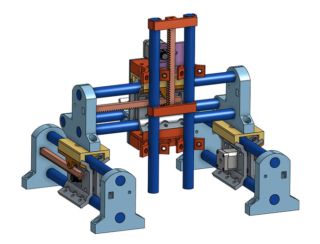
My MPR&P machine is a junk-box build, an unproven work-in-progress, and in no way intended to compete with, replace, or modify any existing V1 design. I’ve presented it as a simple, conventional, 3-axis platform using early MPCNC-inspired, plastic and conduit, skate-bearing style of construction… coupled with R&P drive on all axis. It is, for me, a “laboratory curiosity”… and simply a way to occupy time and satisfy my curiosity. Nothing more.
– David
2 Likes
I am not suggesting it should complete with anyone. I am just like you curious if I can solve my problem by using your design but instead of using R&P drive, use the MPCNC set screw drive that has been tested.
No, an LR4 is designed the way it is for the use case it’s intended for.
The MPR&P is a very interesting experiment into what might be possible for a mostly printed machine- and in fact I’m building one to play with- but it’s not what I would consider a production- ready machine.
No, you don’t just need a different set screw. (Lead screw)
The LR4 is a flying gantry with the Z steppers on each Y axis end lifting the gantry up and down. It uses auto-leveling to square the machine, including lifting the gantry from those locations.
Something like an MPR&P might be able to give substantially more Z axis travel than a stock LR4, but this is a use case well outside of a simple mod. MPR&P and LR4 are not legos and do not simply interchange. Same with MPCNC.
Let’s walk through your use case from a requirements point of view.
What cutter are you going to use, with which spindle, to provide you with how much depth of cut?
How are you going to evacuate/manage cuttings from your work piece?
What tolerances do you need for the work product that you are producing?
What CAD/CAM are you using for these jobs?
With some of that we can start talking through some of the design space choices you’d make for your custom machine.
1 Like
Hello everyone,
I guess I should have started with some introduction.
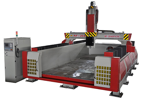
I’m currently planning a LowRider V4 CNC build to shape EPS foam blanks for stand-up paddle (SUP) boards—specifically cutting 4’x8’x8" blocks. While I’m new to this particular machine, I’m not new to motion systems or CNC principles. I’m a mechanical engineer and have previously designed and built custom cartesian robots before the era of consumer 3D printers. That said, I’m reaching out here because I value the practical insights of those who’ve built and run the LowRider platform firsthand.
Here’s my current setup and thought process—feedback is very welcome:
What cutter are you going to use, with which spindle, to provide you with how much depth of cut?
I’m planning to use a 1/4" upcut spiral bit or flute-style foam end mill, optimized for EPS foam. For the spindle, I’m leaning toward a Makita RT0701C or a DeWalt DWP611—both widely supported on the LowRider. EPS is a forgiving material, so I expect to cut up to 1.5" deep per pass, possibly more if rigidity allows.
How are you going to evacuate/manage cuttings from your work piece?
EPS generates a lot of clingy, static-prone debris. My plan is to use a dust shoe coupled with a Shop-Vac or similar high-CFM vacuum, running through a cyclone separator like a Dust Deputy to minimize filter clogging. I may supplement this with low-pressure compressed air to clear the bit path if necessary.
What tolerances do you need for the work product that you are producing?
I’m targeting ±1 mm tolerances. Since the boards will be laminated and hand-finished, this level of accuracy is sufficient, but surface smoothness and profile symmetry are critical at this stage.
What CAD/CAM are you using for these jobs?
For CAD, I primarily use Fusion 360 to model the board shapes. For CAM, I would generate toolpaths in Fusion 360—though I’m also open to EstlCAM for simpler jobs if it integrates more seamlessly with the V1 firmware.
Thanks in advance for any advice—especially regarding rigidity upgrades, dust management tricks, or real-world depth-of-cut limits. I’m looking forward to joining the community and learning from others who’ve dialed in their LowRider builds.
—Eli
Hi, have a look at these threads, might get be useful info
I have a few 3" endmills that are 3/8" diameter with 1/4" shanks - you get them from ice carving supply places. If you can flip the job and built a drop table or some middle-free build you’d be able to mill the top side, flip and mill the bottom and then would only have like an inch or two of foam to hand shape to match top to bottom. Far easier build, less engineering, but trickier to run - flip jobs take some head-scratching until you’ve dialled in your machine (and your brain).
Have a look at my LR32 build. There are a few recent builds also that use just side rails, no “bed”.
1 Like
Hey. Thank you for sharing. You and I spoke over at Youtube. You have responded to several of my comments on your videos.
I already stated building the LR V4 so I don’t think I can easily switch to MPCNC.
I like your design and solution to our common problem.
My planned board doesn’t have much profile on the top. It is all mainly on the bottom that I want to carve out with CNC.
Do you have any ideas on how to modify the LR design to beable to do what you have been doing?