Further to my above thoughts on the y rail. I am considering going to a smaller y rail so the bearings get more leverage. Currently using 31.8mm Y rail - I suspect a 27 or 25mm Y rail would resist rotation quite a bit better.
But because of my other uses cases for this table I might just skip that mod and go the other path I’m thinking, which compromises geometry a but I think(hope?) I can make up for that by boosting rigidity significantly.
Don’t take this as criticism at all BTW, purely curiosity. I can see how much you shaved to get it that close. There is a spot on the bottom spindle mount where front to back its like 1.4mm. There is at most 5 mm you could push the spindle back and that would require the core being open - having a hole in it around the back of the bottom spindle mount AND would make dust shoe design even harder. Gets very tight at the top of a router if you do that too.
Yeah, the mount does add a couple mm’s but it also bands the router in place. If you bolt straight to the core, it will rip it apart at the layer lines. Even more so because some areas are only 1.5mm thick.
The angle stays the same, to get a better grip you would need to modify the bearing angle and the yclip angle. I do not think there is anything to gain there. The weight of the machine and the tiny force the router generates it is not going to come off the rail unless something really bad happens and at that point coming off the rail is better than breaking something.
Interesting topic here … with this side mounting of the motor, could it be an option to run two motors facing each other connected to the small pulley on a common shaft? I have never run a common shaft on two motors myself but always wondered about it. (Mostly prompted by a surplus of motors on my shelf …)
Not recommended at all. There is an issue we see on “AWD” 3d printers, where the steady state of the motor when powered down are out of phase by a degree or two. When powered they move to the closest full step in most instances. Then you can end up with two motors fighting one another. Causes issues. There are ways to “sync” the motors but its easy to get wrong, a pain in the bum and it may fall out of sync. Requires everything to remain the same and perfect which is not realistic.
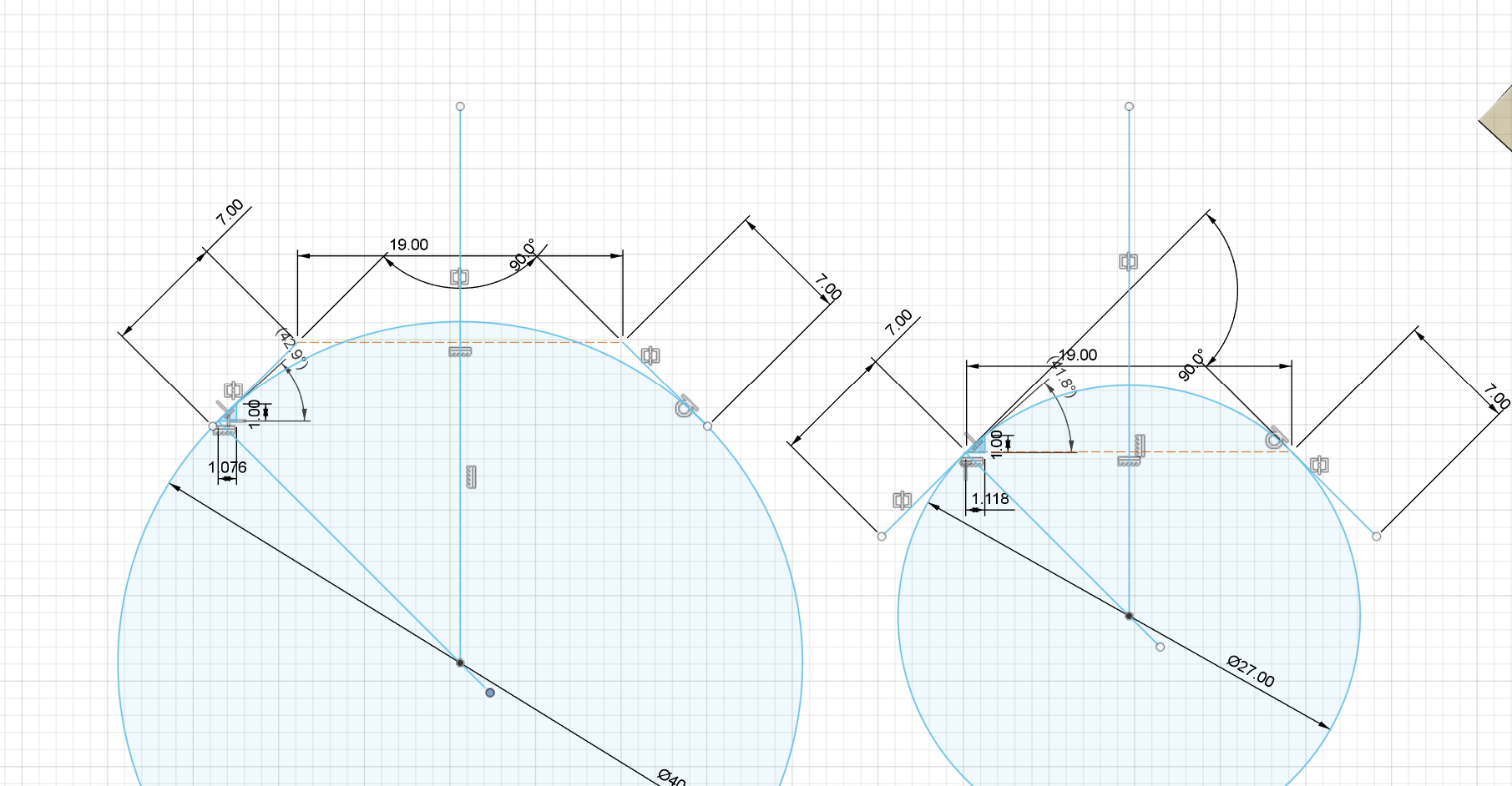
yeah so I double checked my work on this. I was aware that because the bearing angle is 90 degrees the contact point tangent is parallel to the bearing surface - so the position remains perpendicular to a line that runs through the centre of the tube. Relative angle is the same
Where I was thinking about this wrong is that under in induced torque that causes the bearing to climb up the tube - I had thought that the angle of attack for it to climb say 1mm up the tube was significantly higher with a 27.5mm tube than with a 31.8mm tube. But my intuition was wrong.
good to be wrong because it means I don’t benefit from changing my tube between now more major changes I’m considering(changes that make it in to something that is no longer a nice low budget well balanced lowrider, only lowrider in lineage)
Your spoilboard in the last post looks pristine still, maybe you should just cut a few projects before planning major changes.
There have been others who approached it that way, planning major changes before having really used it. The results have always been a mixed bag so far.
That’s the second side of the spoil board. I’m afraid your assessment about how much I’ve used the machine isn’t correct, and that photo doesn’t represent what I’ve done with it… Also most of my projects have been at the end of the cutting area, not in the middle.
I’m also able to assess performance through various tests to see if it meets my performance and functionality goals, which I already understand.
I think the lowrider is amazing for being able to do what it does. It’s a fantastic machine. But it also doesn’t quite meet my goals. It’s a great platform to work from and has allowed me to knock out a couple of projects that I couldn’t do with my smaller machine. However, in-between projects I will continue modify it until it meets my goals. .
This is isn’t my first machine. I appreciate the thought process, but I would suggest if you think I’m modding out of ignorance for the sake of modding you would be incorrect.
I don’t think they are actually 90, this is another place I squeezed every last bit out of it and was still able to hold the Y rail.
Doesn’t change the outcome though.
I love the critical thinking. Whenever we start the next project we need you around to keep an eye on things and help with decisions. As you know it is pretty easy to convince yourself of a good choice and miss the obvious ones. Having lots of critical eyes makes things fall into place faster.
TheMrFish’s friend in NZ checking in here on some progress with the gear reduction he designed.
My LR4 has a cutting area of 1280x2500 and I’m using a 1.5kW air cooled spindle. I’m using 3mm wall pipes and because of that, I’ve also been able to bolt the braces into it. I’ve now added a 3:1 gear reduction to both X and Y.
The steppers are running on 45V and I’m using DM556T drivers to do so.
I’ve tested the rapids all the way to 18000mm/min and it didn’t fail: https://youtu.be/szJFwF-XpEs
I’ve also done quite a few test cuts. This is 10mm DOC full contour, 21k RPM, 3800mm/min feed with a 5mm compression bit: https://youtu.be/CUc38A81wIY
It’s very impressive results. When my dm556 come in I’ll be running the same tests on my OMC steppers at 24v and 48v. I’m currently using tmc2209 in standalone mode and I’m not confident I have set the current properly using the potentiometer and a multimeter. Lower micro stepping should also help.