
2 Likes
so as you can see the motors really start to get in to the less useful part of the torque curve at around 450rpm in general.
Lowrider specifies 16T pulleys, 2mm pitch - 16 * 2 * 450rpm = 14400mm/min. The system is large and heavy so with loss and reasonable accelerations I found that was more like 11000mm/min on my machine which is 183mm/s - right in line with what you were saying ![]()
I have dropped my top speed to 60mm/s for(hopefully… lets test!) tradeoff of higher DOC and/or potentially better handling of wider bits.
I certainly would not suggest this for cutting thin MDF/acrylic/ACM. Nor would this be good for a plasma cutter or laser cutter. But I if you want to use larger bits or go deeper in thicker material, or do things like slab flattening with larger bits, or do a little more aluminum work I suspect the tradeoff will be worth it, especially with a higher powered spindle.
But lets take the thought process to the conclusion - if I need more speed I can
- reduce the reduction from 2.5:1 to 2:1 by going to a 20t pulley on the reduction gear - that gets me to about 92mm/s (11000/2=5500, 5500/60= 91.6mm.s)
- go to 48v - expensive option as I need the drivers(already have the supply) but looking at the graphs it hits about the same torque as it would @450rpm@24v at about 880rpm.
So roughly: my 11000mm/min real world performance and divide by 450RPM(24v voltage useful torque), times that by 880RPM(48v voltage useful torque)=21500mm/min. with 2.5:1 reduction that’s 8600mm/min or 143mm/s - quite respectable. 2.5x the torque at 78% of the top speed. - do both 48v and 2:1 reduction 21500/2 is 10750mm/min or 179mm/s - 2x the torque at just under the same top speed.
2 Likes
Please don’t take me for thinking everyone should do this. I think the selection of pulley size and no reduction is just right for an all around performer in the stock configuration.
Nor do I think for most people going to 48v, adding more components and complexity etc makes any sense at all given the performance of the stock machines and the costs required to make the jump to that - not unless you already have a lot of the parts in the parts bin and are a pretty experienced builder with some CNC time under your belt. Its more shit to troubleshoot, more variables at play to deal with.
4 Likes
I feel so much better knowing you understand what you have done. Thank you so very much for taking me along your path of reasoning. And I fully agree with you!
Now we just need to know what sort of forces are actually experienced and we could probably both come to a gearing agreement. I always use 9.5lbs as the high end for a cutting load but that does not account for the spikes that come from poor CAM, or knots/hitting screws.
Large LR’s benefit pretty greatly from a faster rapid, but the MPCNC, that might benefit more from different gear ratio, smallest pulleys I think I can get are 12T though, without doing a gearbox/more parts, and that leaves very little tooth in contact with the belt so the drive would need to be redesigned.
3 Likes
I’ll see what I can find regarding forces. Most of the calculators I have worked with for cutting force are really assuming a very large rigid machine cutting steel.
Regarding gearing and MPCNC - I think that would make sense. Smaller pulleys handle less torque - the gates manuals have some super useful tables that I have used for belt/pulley/motor matching previously. Let me track them down and will post here.
2 Likes
Here is the GT3 manual. GT3 belt has a lot higher torque handling than GT2 so I will need to find the right manual. Note that its an expensive option, but GT3 is one way to get more torque handling with the smaller pulleys on the MPCNC if you did have to do 12T. But the smaller pulley size is still a big loss. Probably better/cheaper to use reduction and GT2 belts - especially given how cheap some of the reduction sets are on aliexpress. It would add quite a lot to the BOM in the way of extra bearings, shafts and pulleys. Could be a good optional mod.
relevant page is page 18
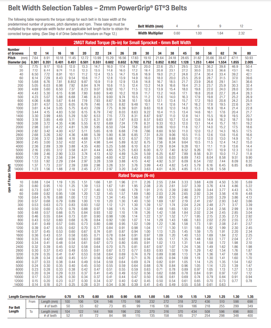
this lays out the relationship between belt loop length down the bottom - length correction factor is not super relevant to open belts - or I don’t know the appropriate way to use it, so applying a safety factor for that is a good idea.
But also has the width, pulley size and RPM on torque handling.
Because stepper motors have most of their talk down low I only really look at the top line of 10RPM, though for appropriate safety factor it doesn’t hurt to do it at 500rpm where the torque drops off on the stepper motors.
This table also explains why I am happy using 6mm belts on the reduction gear, because as you can see the larger pulley can handle the torque even at smaller belt sizes.
Will find the GT2 table and post.
Really struggling to find the GT2 manual that includes 2mm pitch… I wonder if they have taken them down? I should have kept a copy.
1 Like
I’m at a loss. eh regardless, the GT3 table is a useful guideline and importantly demonstrates the relationship between these factors.
1 Like
Yeah it seems to have disappeared a long while ago.
Still have not done more reading in to cutting forces but I will.
1st data point is back. Mate in NZ - he is running a 3:1 variant of the above reduction(20t pulley motor side to a 60t pulley)
He is running the LDO 2504 motors at 1.8A - expensive very high speed motors(see tables above). They are running cool, unsurprising since they are designed for 1.8A RMS/2.5A peak in an enclosed printer - so they handle this in open air very well.
He is getting rapids comfortably running at 10kmm/min and just tested 10mm DOC with a 4mm compression bit at 3200mm/min in MDF on X with the 3:1 reduction - a significant improvement in viable DOC over his machine without the gear reduction.
These motors are an exceptionally good match for this setup with the reduction. In the spirit of lowriders budget approach, I don’t know, but they do show what can be done.
I am tempted to pull mine of my k3(printer) and put them in lowrider in place of my OMC 2004s1 motors.
3 Likes
To clarify when I say LDO 2504 I mean
LDO-42STH48-2504AH or LDO-42STH48-2504AC - AH being the high temp variant.
Aka “LDO Speedy Power” motors.
Typically run $30-45AUD each.
1 Like
I’m watching this with interest. I run the 1.5kW spindle now and generally like it and the control over the rpms. I find it easier to experiment and try different speeds with different cutting scenarios.
But I also chuckle. I watched my machine fail many times last weekend, and skipping steps in X was not the problem. It was actually skipping Y steps on the min side. I adjusted the tension on the belt and really improved things, but it remained the failure mode for my machine.
I was cutting aluminum without coolant and also had some problems on some pieces with the chips welding together and increasing the load quickly. I was learning…
I added coolant, and used trochoidal milling to finish the pieces I was working on (and now I have Al struts to install!) Between the bits I ruined, the scrap, and the chips of Aluminum, I’m gonna send a lot to metal recycling. ![]()
I find that when I’m seeing the machine under enough load to worry about the motor skipping, the cut quality isn’t what I’d want.
Do you think the increased torque improves your cut quality or is it purely speed?
Just curious. Gotta learn somehow.
1 Like
That is tough. Ideal CAM and chiploads keep machine load very low. Bad CAM basically means your machine is pushing on a piece of metal…the metal will always win.
With wood chip load is simple and an extremely wide range of acceptable, plastic smaller, metal is a very tiny window of good.
If you keep your machine load under 9lbs you should have no problems, and that is a lot of aluminum removal, but if you start with a lower load that should give you a larger window.
1 Like
Trust me - the Universe was laughing at my ignorance.
But I learned. I was making huge chips, but needed the coolant, and to move slower.
2 Likes
This is precisely the goal, to widen the range of acceptable settings, bits and materials. And to allow the machine more variance in material without issue.
Take for example - I was cutting yesterday - I tend to secure the stock with 15ga brad nails because it’s really quick and easy. But I placed one poorly and it ended up hitting it. Rather than blowing through it - which the router is capable of, newtons 3rd law kicked in and I lost steps in Y
I should really make sure I do not do that - ultimately it was my fault - not at all blaming the machine there, and also get myself a 16ga nailer for this task.
However I also suspect with the right motors, reduction and voltage in can get access to more of what the rest of your design is capable of.
No and yes? I think that it improves the range of acceptable settings, and getting setting closer to the ideal feed per tooth range for the material will improve cut quality. So indirectly.
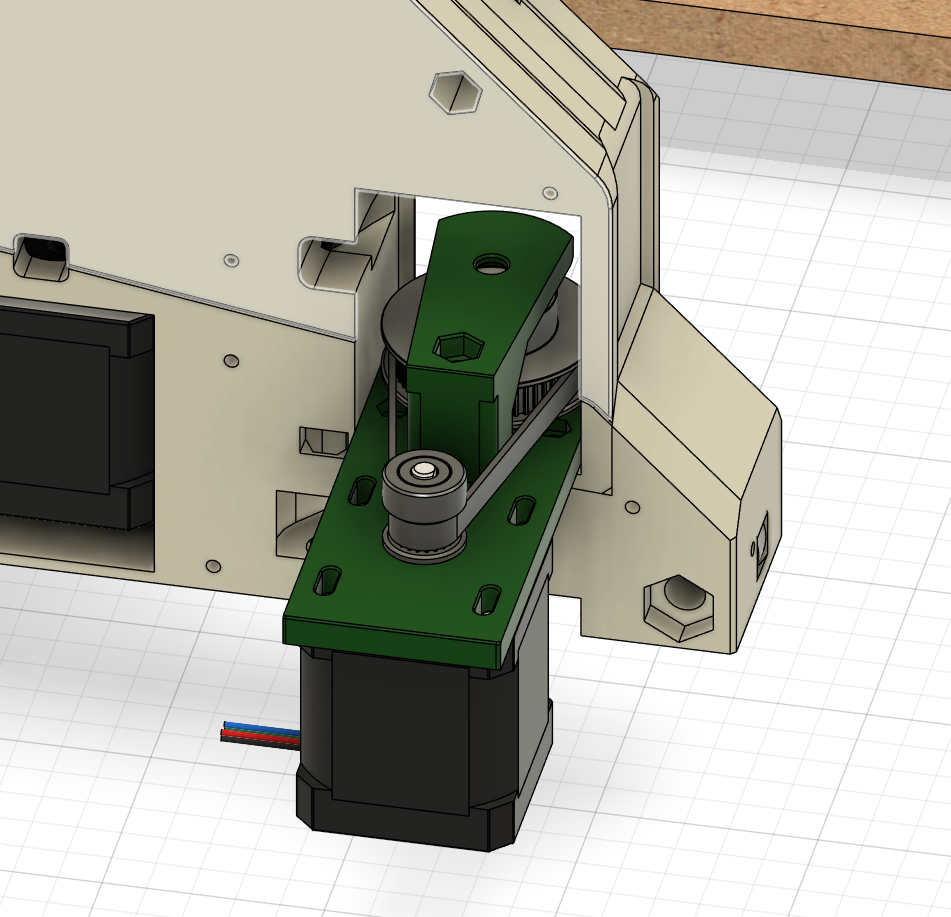
Also I started on the Y reduction CAD last night. Just didn’t have a lot of time so didn’t get it finished.
1 Like
Further to all of this. I think Ryan’s instinct is right. Where there is serious potential for advantage is on the MPCNC, where you have more rigidity available. Much shorter beams means much stiffer beams as beam stiffness is inversely proportional to the cube of length.
Knowing that we can infer the smaller the machine the more capable it is of using the extra torque
If I didnt have a capable smaller machine, I would be very interested in building a 20cm-25cm cutting area mpcnc to see how capable it is.
1 Like
Also I’m not really surprised about this. The design pretty much entirely relies on the stepper motor torque to keep position in Y. It gets almost no resistance from the rail when dealing with opposing forces.
This works because Ryan’s design has such crazy short lever arms and has the least leverage at the lowest position. In other words cutting forces are not multiplied through bad design/design tradeoffs as much as other designs
3 Likes
Every extra millimeter is a hard battle. I have a feeling most people do not realize how much effort gets put into minimizing lever arms. I spent a couple weeks on the LR4 lower core geometry, just trying to get the endmill as close the the lower rail as possible. Everything was built off that. I do have a different section I just guessed on…not going to tell on myself as to which one though.
6 Likes
Given the rear section of the spindle mount adds bulk, did you consider deleting that and just having a front clamp? Would require specific cores for different router geometries but could bring it back a few mm further. My assumption had been this choice was for modularity and minimising the number and size of specialised parts in the build, but keen to hear your thoughts