Yeaaaahhh ![]() was not pleasant
was not pleasant
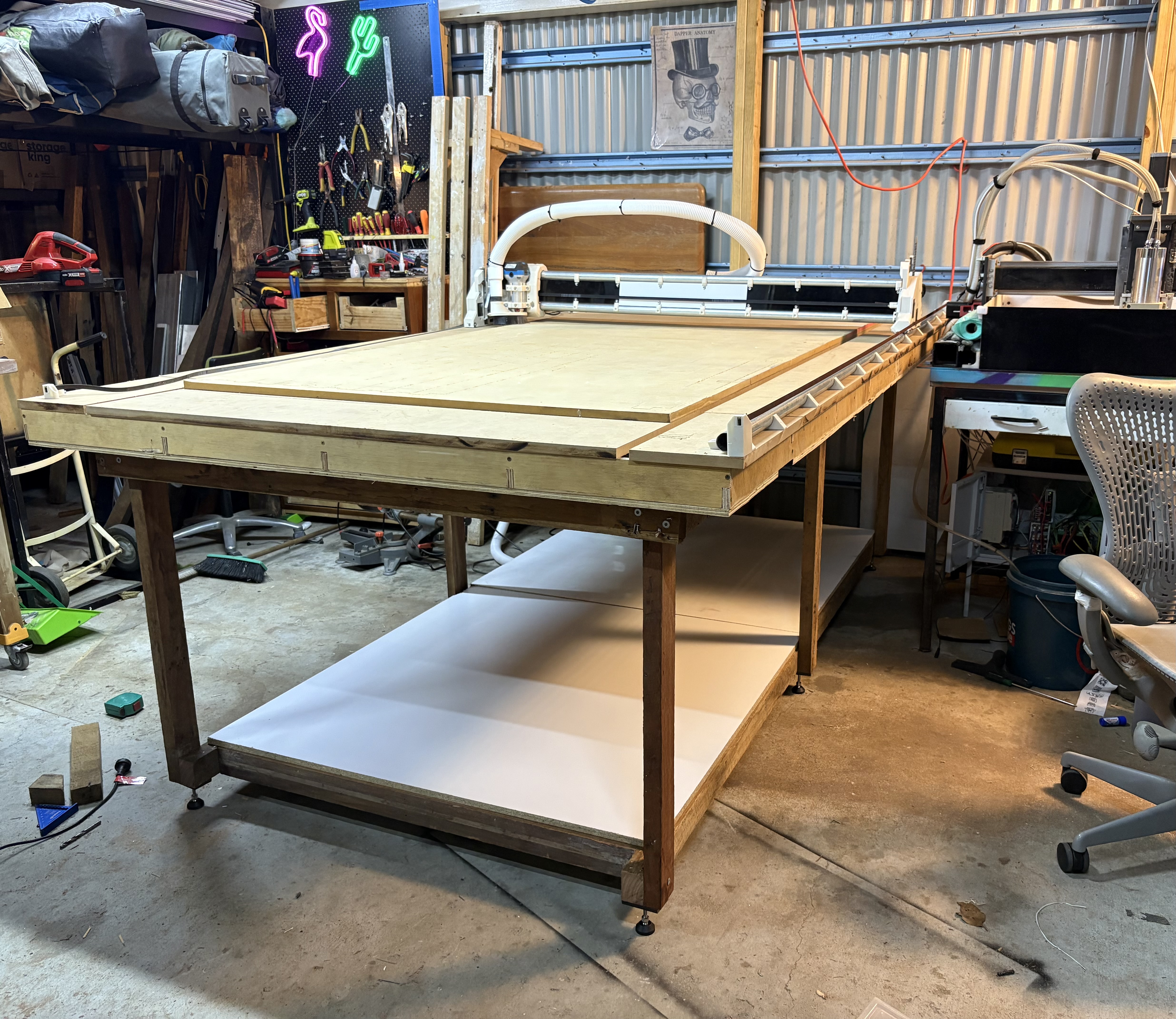
Time to tidy up.
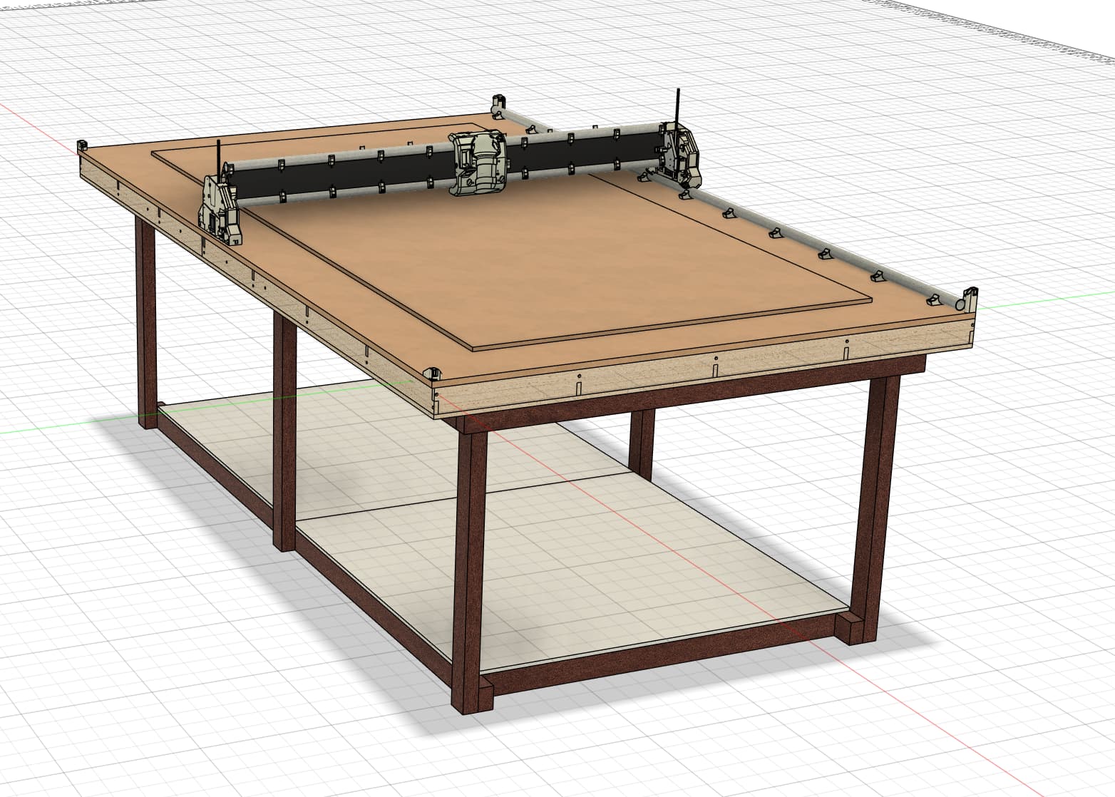
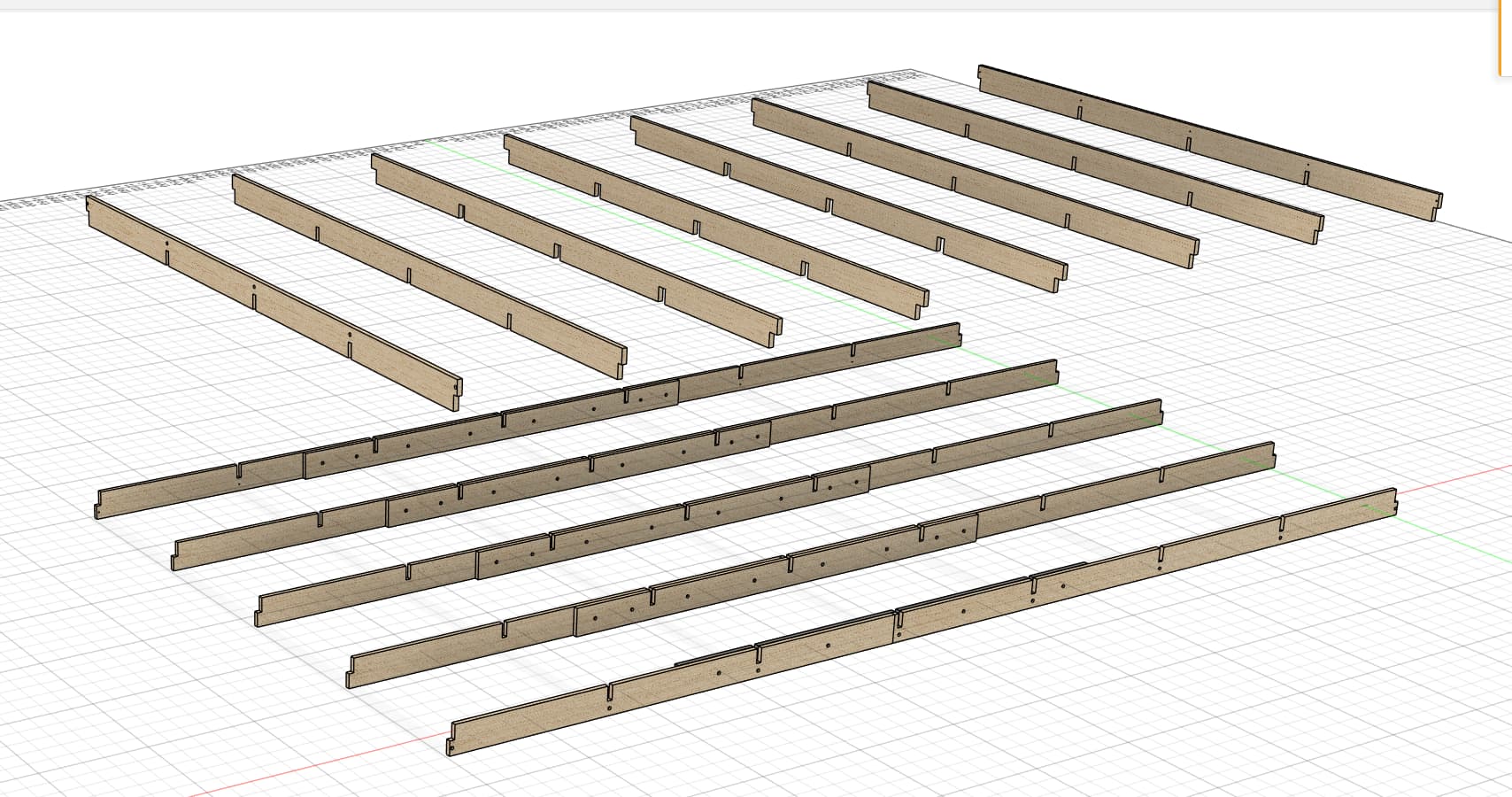
Table top was made by cutting salvaged large pallet plywood in to a torsion box structure, and skinning with more salvaged ply and MDF.
Base is made out of old hardwood studs pulled from a house someone was renovating.
I did pay for the levelling feet however.
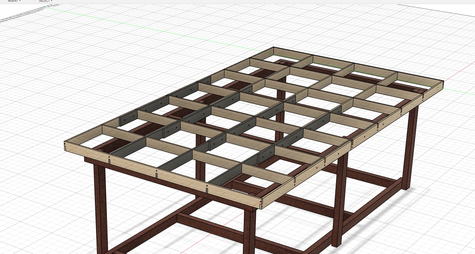
Torsion box core structure is cut from a single piece of material, then sloted and screwed together.
Top and bottom is mostly nailed on with larger size brads and a couple of screws. Should make replacing/upgrading the surface later easier.
2 Likes
Looks nice. I would consider adding some bracing to the base. That doesn’t seem like it would be very rigid and may sway a bit. I would likely add horizontal 2x4s all the way around or diagonal corner braces.
1 Like
Yeah. I’m just adding some gusset type braces around the tops of each leg once it’s perfectly levelled. I just didn’t mention that in the post ![]() my workshop floor has a 2-3 degree slope so it’s far better to add them once it’s fully levelled in place.
my workshop floor has a 2-3 degree slope so it’s far better to add them once it’s fully levelled in place.
It’s surprisingly more rigid that I was expecting however.
100 year old Australian hardwood and 100mm batten screws - the joints ended ho far stiffer that I thought they would. 5mm thick batten screws can do a lot of heavy lifting but are not great for sheer loads. But they have pulled the joints together nicely. That’s where the triangular gussets come in and they will be screwed and nailed.
2 Likes
I’ll picture them once done
Dang! I have a bucket of various feet just sitting here waiting for a use. We need to somehow have a V1 Marketplace, everyone do a stocktake and just have stuff sitting in an inventory for times like this. If you need any more give me a shout.
1 Like
Honestly I’m just happy to have been able to build this thing with a total outlay of $35 ![]() total cost for the full lowrider build has been $285AUD at last count as I already had so much in my parts bin. Not counting filament…
total cost for the full lowrider build has been $285AUD at last count as I already had so much in my parts bin. Not counting filament…
The parts bin provides….
4 Likes
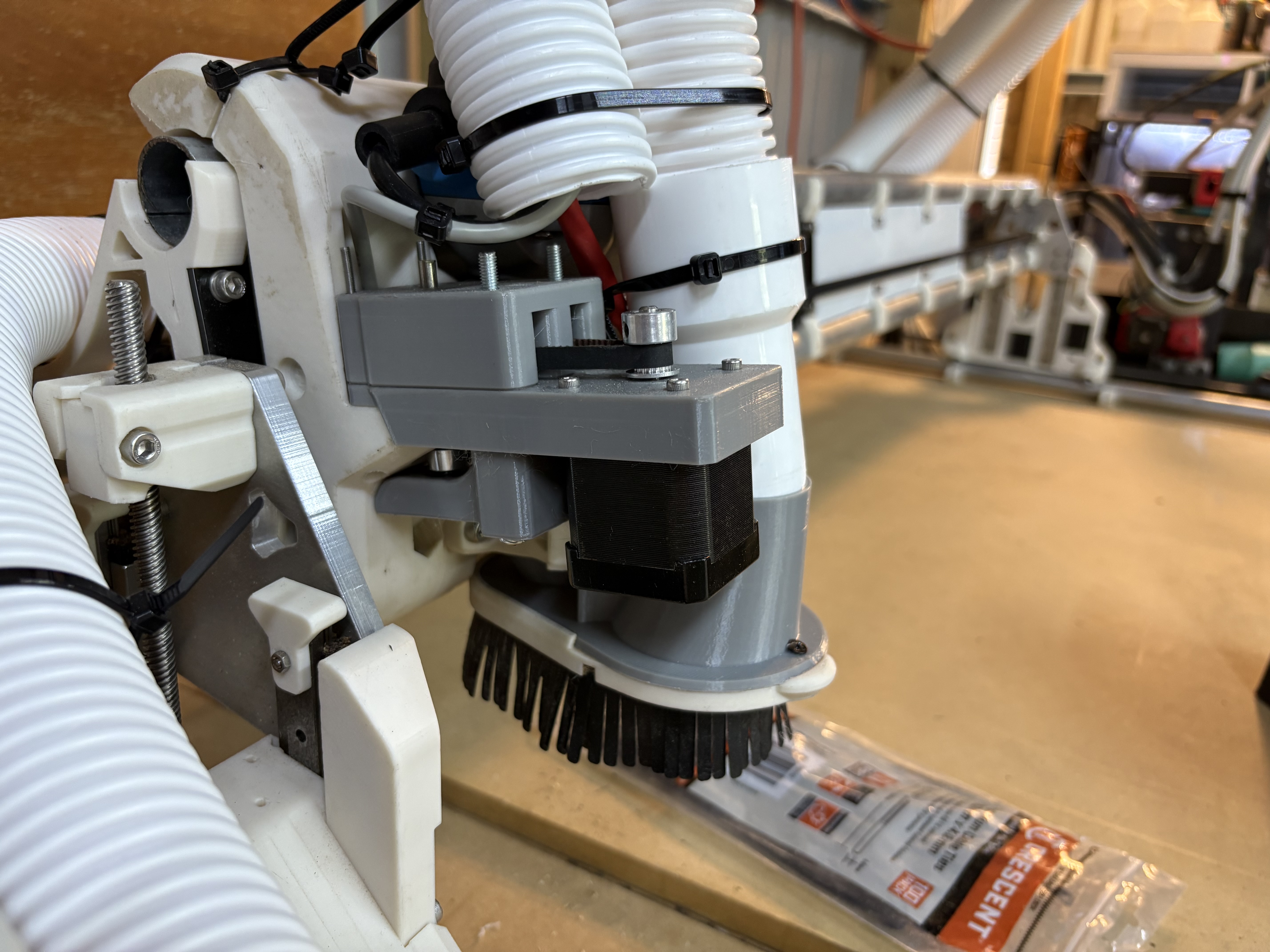
I had noticed each time I had a cut where the spindle seemed to run away - catch and lose steps taking my cut off path - the step loss occurred on x. Obviously this can be avoided by getting an appropriate depth of cut - but my observation currently is it’s the motor power on x that is my current performance bottleneck
I have added a 2.5:1 reduction to x. This limits feed rate to 4500mm/min in testing but gives me 2.5x more torque(minus gearing losses which should be minimal… 2.49473773x torque ![]() )
)
I think 4500mm/min is enough for my needs.
The wisdom/effectiveness of this choice is TBD - the proof is in the cutting.
If it works I’ll design some reducers for Y as well, since I’m not going to use more than 4500 on Y if I cannot go faster than that on x, so may as well benefit from the extra torque.
Of course removing this bottleneck may just elevate the next one - if this ends up a waste of time I will update this post saying so.
3 Likes
And if 4500mm/min ends up being too slow for me for whatever reason, but not a lot too slow, I could push out that number by going over to a 48v system. 48v doesn’t increase the torque, but it does lengthen the torque curve out, so should give me more available torque at higher rpm.
Gears add slop. Stepper have more torque at lower speeds so if you were actually having problems not using the gear reduction and just slowing down will give you far more power than reducing and running faster. The torque curve drops off very fast.
With that said, these machines, setting and parts are not new, there is no lack of power on the X axis. You either have bad CAM settings or a dull (or incorrect) endmill.
I totally respect this perspective. And the machine works very well without it. This is an extremely well balanced machine - through good engineering(good material choices, reduced moments etc) it does a lot with very little.
And you are right any additional system adds backlash. It’s absolutely tiny with gt2 belts. Far less than the inherent flex in the system. To the point where on my other machine(much smaller RHS based machine with gt2 reduction) I’m easily able to get sub 10th of a millimeter precision in steel and aluminium. So I don’t think that’s a significant concern here.
As far as having no lack or torque - simply put more torque means more headroom - less chance of failure and deeper depth of cut, at least on paper. Also more ability to finish a cut with a dull endmill, and potentially less chance of going dull in the first place because the cut is more controlled(though this is more equated to machine rigidity than motion system power)
As we all know greater depth of cut means more force on the tool. It’s a delicate balancing act between the faces the spindle can deal with and the forces the motors can deal with, especially on a lowrider where irs so well designed and so well balanced.
.
However because I want to run the rapidchange clone I have designed I need a reversible spindle. Choices being 800w 1.5kw and 2kw. Looking at performance vs weight 1.5kw makes a lot of sense. This shifts the balance somewhat too.
This also significantly increases the doc that the spindle can handle. And given what I have witnessed with the machine so far, and from what one of my mates over in nz has observed with his lowrider with a 1.5kw spindle I have a reasonably high confidence this is in fact the lowest hanging fruit and the most present bottleneck with regards to performance of this machine
With motor reduction running cuts under 4500mm/m, based on cnc calculators/cutting force calculators I can predict with very high confidence that I will be able to take deeper depth of cut with the reduction gears in place than without them.
Fortunately for all of us, with this reduction gear this theory is easy to test - since it takes about 10 mins to install. So I will test with the genmitsu router I have now, and with the 1.5kw spindle when I get it. And I will post my results.
I have the utmost respect for the engineering, the sweat equity and experience you have brought to this latest lowrider. If I’m wrong on any point I will be extremely happy to admit that and share those results.
My friend in NZ is printing now and will also test with his setup. His machine is a little smaller with a 1.5kw spindle. Yay more data!
Who doesn’t love some data points.
3 Likes
What are you using for the gearbox? I am guessing a couple pulleys stacked?
Correct. Just 2GT 16T->40T 40T is on a shaft that attaches to the normal drive pulley for X. Shaft constrained with some F695
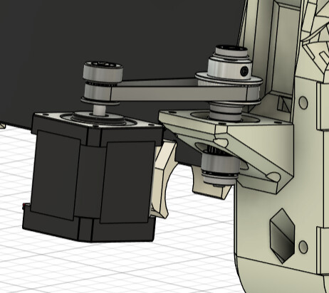
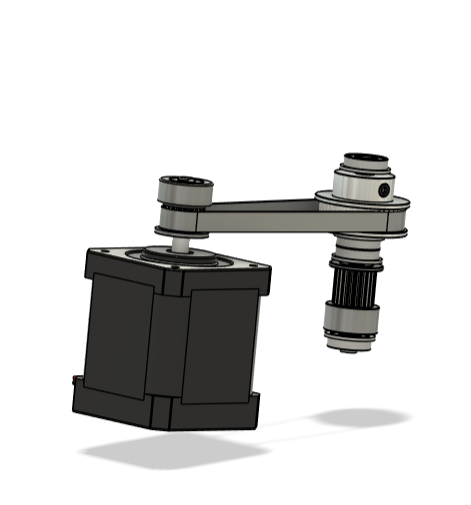
There are some washers between the bearings and pulleys that I didn’t actually add to the CAD, just left space for them
2 Likes
Slick!
1 Like
My comments earlier come from nearly the same thinking. We used to use allthread for the zaxis, it should have had a ton of lifting power. The mechanical advantage was awesome…but it was so slow that when we increased the stepper speed they ended up being so weak the Z axes used slip and skip. We maxed out at 8mm/s, 10mm/s would have so little torque the friction of the screws would stall the steppers.
Now I know to tune the machine to the speed I want more than the power I think I need.
It is pretty harmless to test force. You can even just use your hand and feel how much it takes to make it skip at different speeds. I think currently we can rapid at 150-200mm/s (with little power) but have peak torque at 30mm/s and under. If I remember correctly.
1 Like
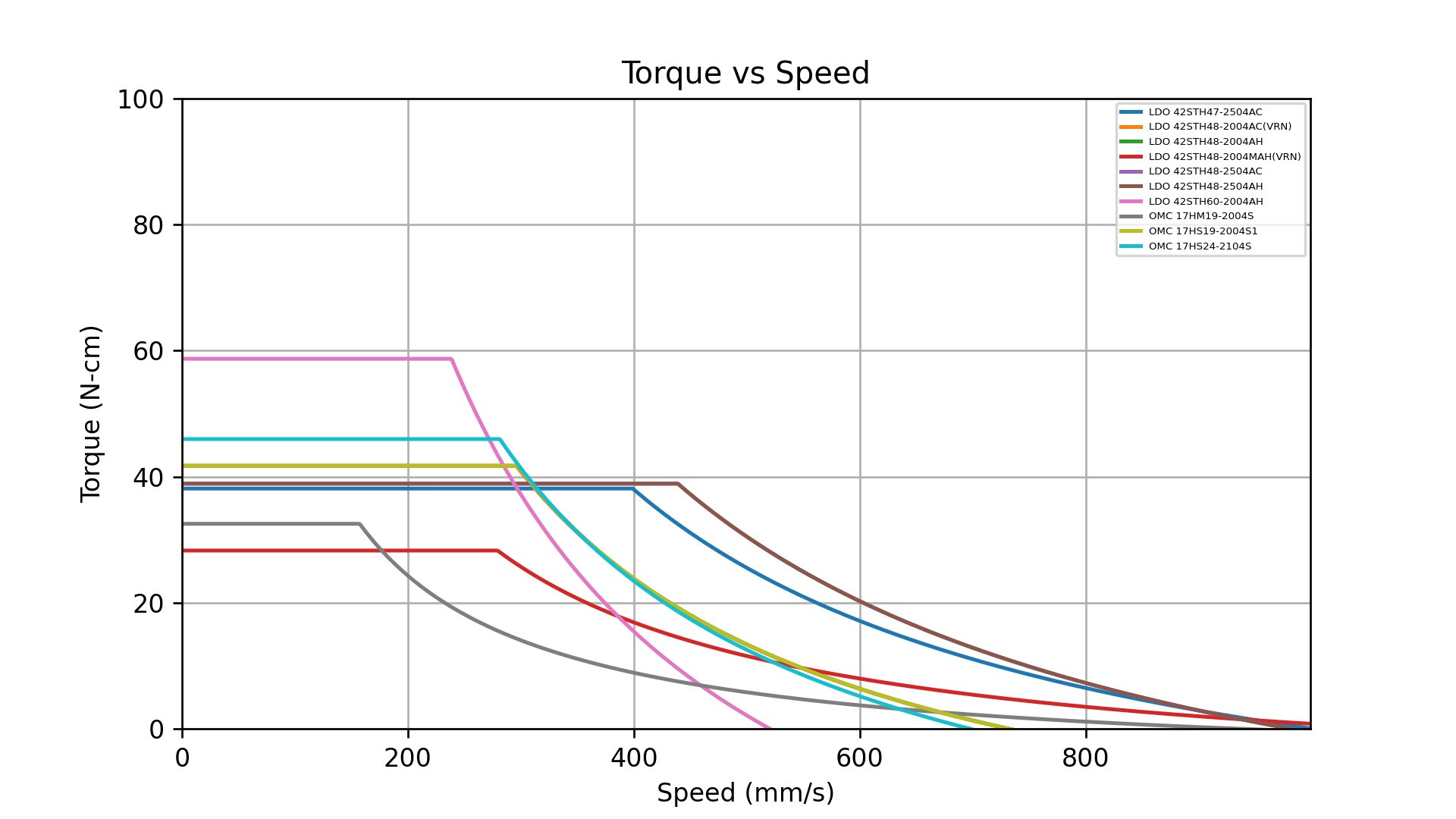
Yeah. It’s very much motor and voltage dependent. As mentioned above higher voltage doesn’t give you more torque but it does stretch out the curves a lot. I’ll find some graphs I pulled and posted elsewhere using Eddie the Engineers python calculator. My experience with testing real world performance against the results of the calculator is they match very closely, and it just scales depending on the particular system(more weight, resistance from changing belt direction, resonance) but they scale in line with the graphs so a very useful tool when selecting motors.
I have used these graphs to explain why most people do not need 48v in a 3d printer even if they want high performance. If your high performance motor can do 2000mm/s with 48v but you are printing at 450 with 600mm/s travels then capping out from back EMF at 650-850mm/s on a on a 2209 at 24v is not a limitation to print speed. Its only if you want to go faster than that when it makes sense, and we just don’t have hotends that can keep up with that. For example. 700mm/s * 0.2mm layer height * 0.8mm line width is 112mm3/s of hotend flow you need. Pretty much the only thing that does that kind of flow is a supervolcano - and they are unsupported - you would probably break the heatbreak at those speeds.
But I digress.
The graphs also back up my prior that when it comes to value/performance the OMC 2004s1 motors are king of the hill for performance per $ - when you can get 5 delivered for $80 AUD they are hard to beat.
1 Like