I have some updates from the last 2 weeks.
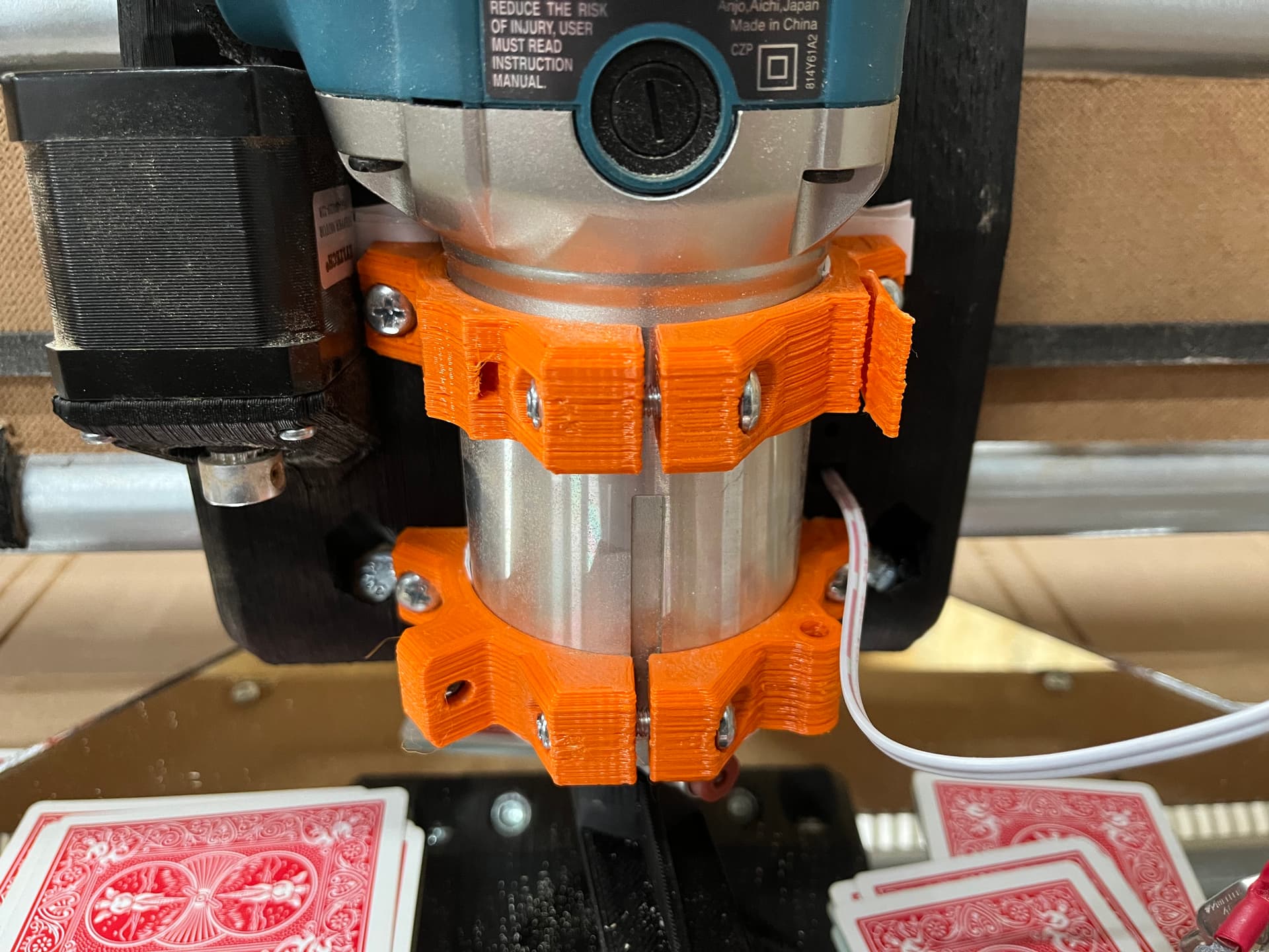
@azab2c Printing the dust shoe at 99.5% scale did the trick. It is now tight and I have 25mm and 35mm bristles on separate shoes.
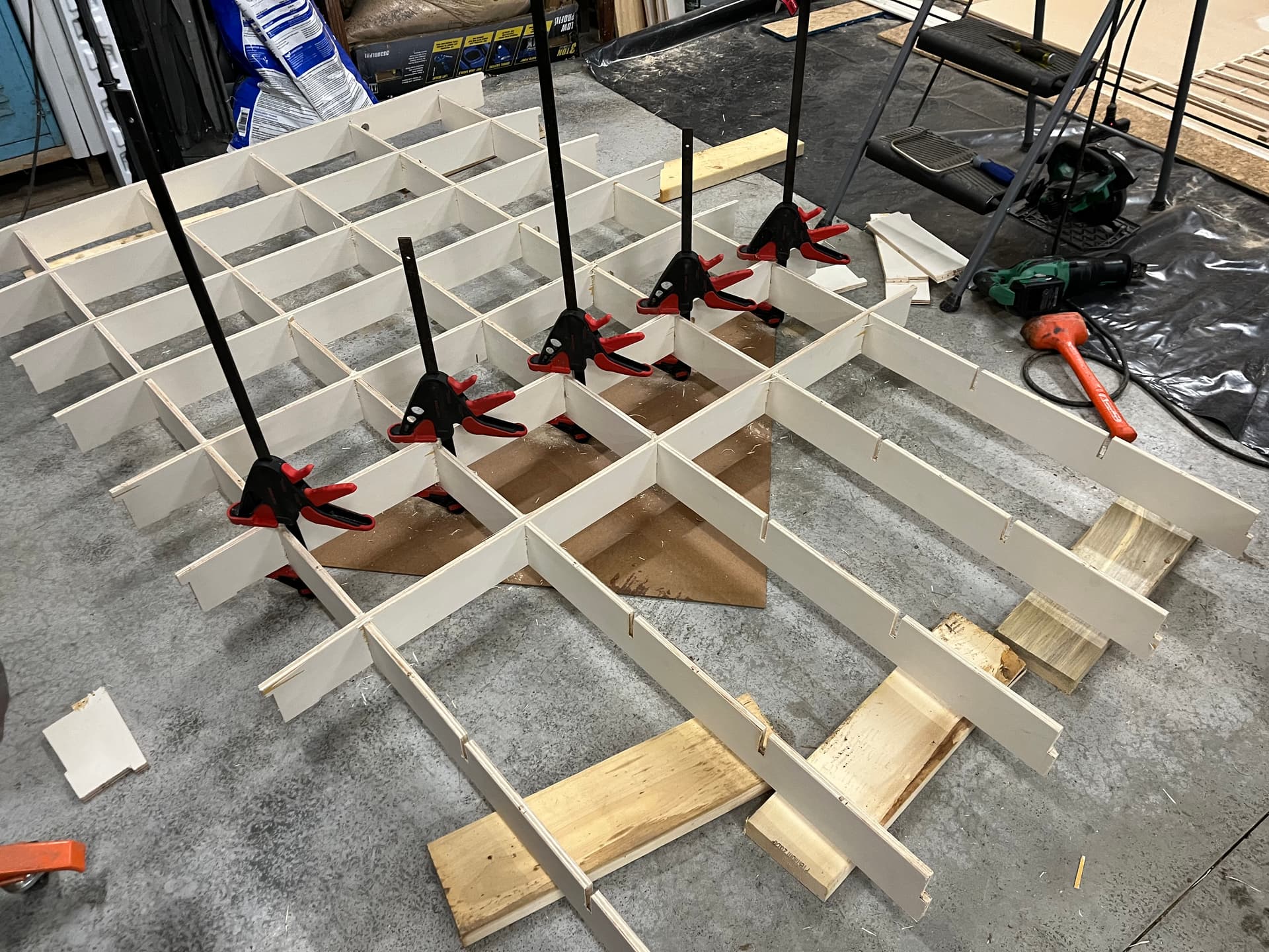
The good news is that the table build went much better using clamps to insert the X-ribs
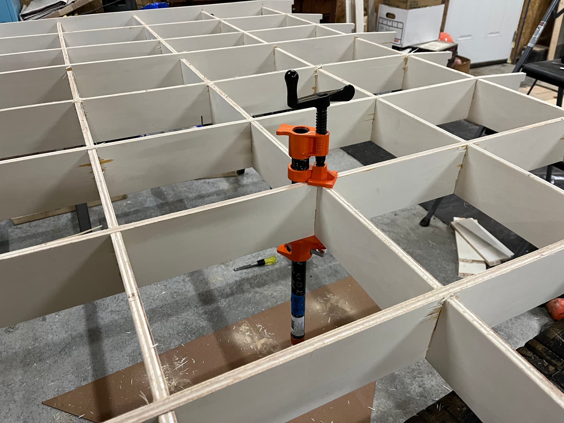
The squeeze style clamps could only generate so much force so I used a screw style pipe clamp at each intersection to get the final 1/8”

I pre-drilled and installed screws at each intersection to make sure things don’t pull apart down the road.
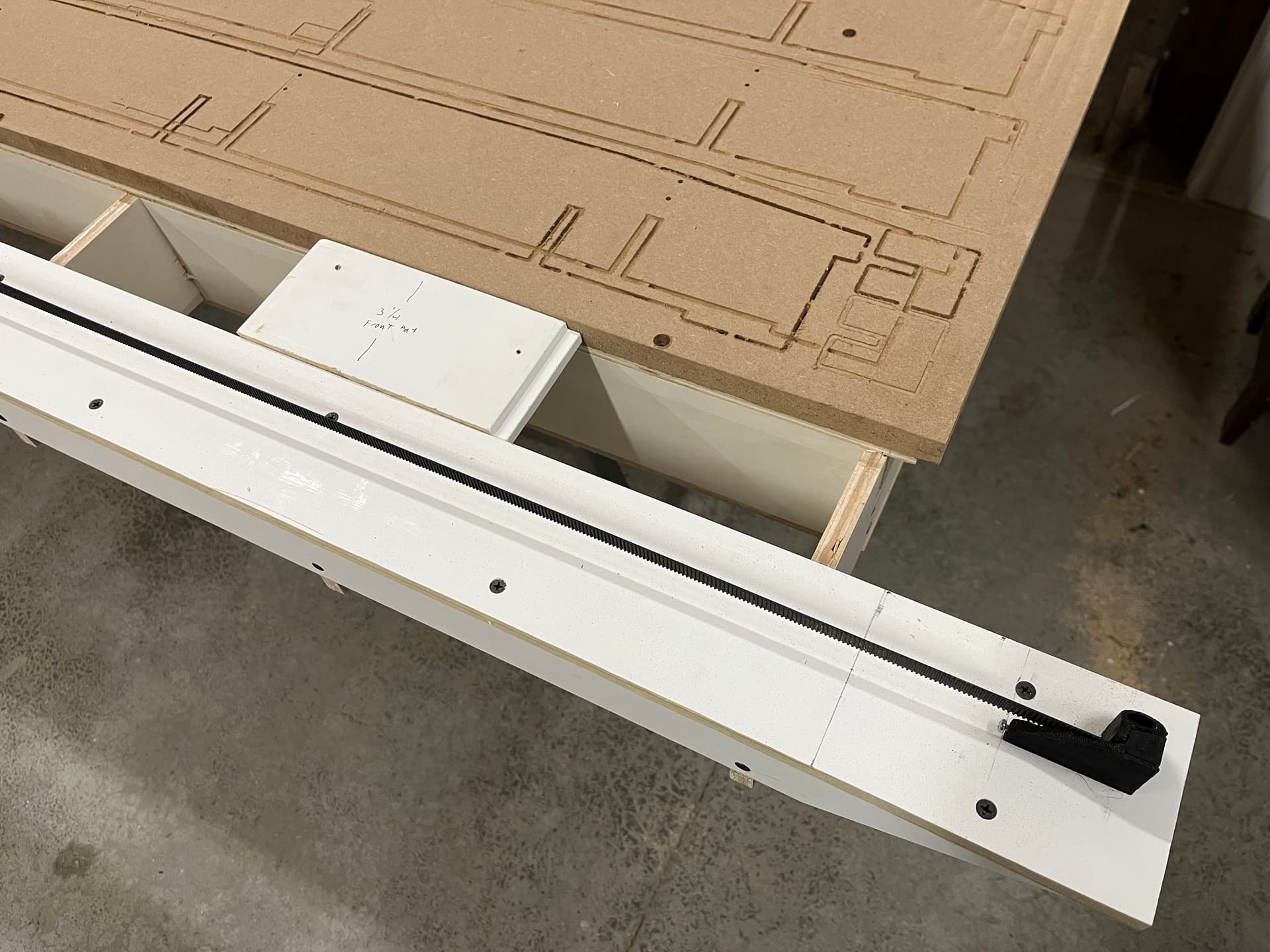
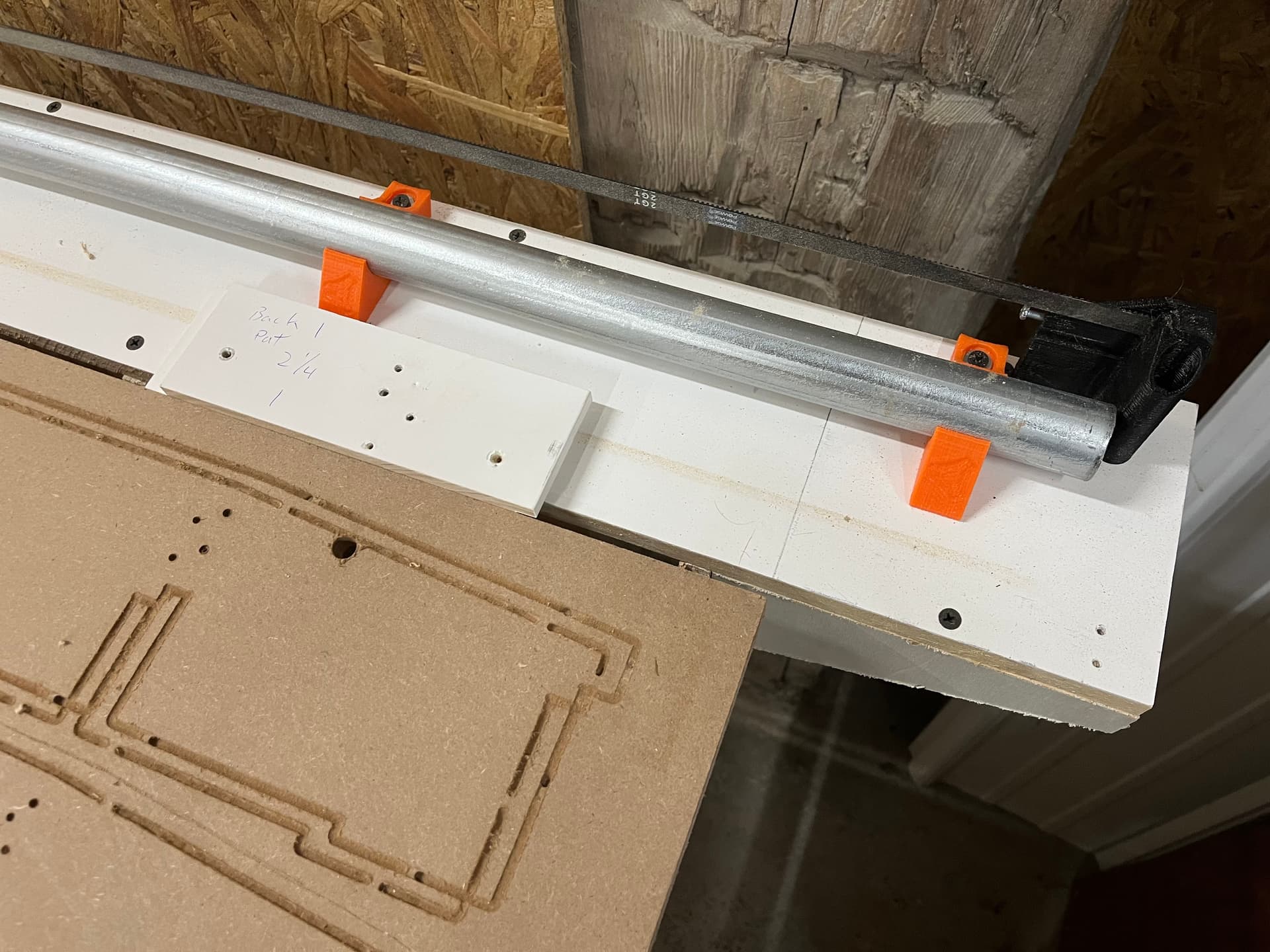
For table assembly I got the MDF spoilboard attached to the table as square as possible and then measured from the MDF using spacer jigs to make sure everything else was dead on.
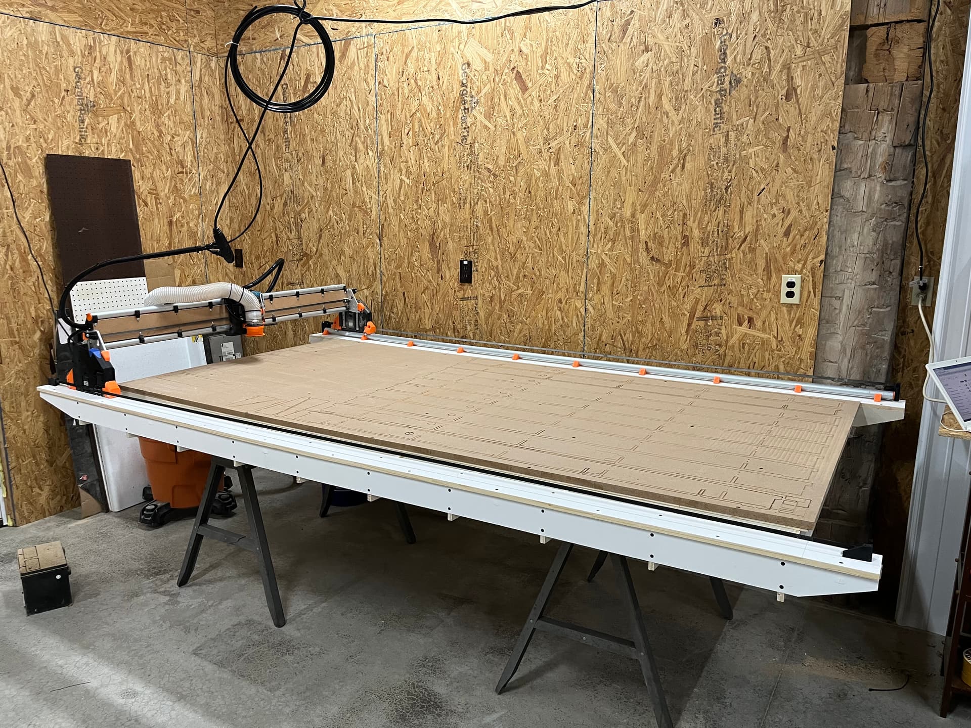
Now for the bad news on the table. As I knew, my joints were a little tight. Once i got everything together and sheeted I realized that the whole table has a bit of a smile along the Y. My recommendation to others is to make sure your slot width is dialed in. Being too tight will create a bowed table.
The good news is that the gantry rides along the smile and I only had 1mm of variance along the 8’ of Y. Whatever workpiece I lay down will just need to bend slightly with the table.
The X had about 2.5mm of variance due to a smaller smile going the 4’ direction.
To get rid of the high center along the X I started surfacing with a ½” dovetail bit. In doing the first 1mm cut I saw that the router needed to be trammed.
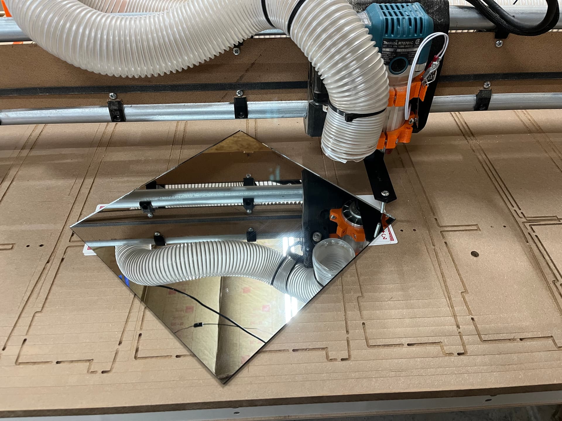
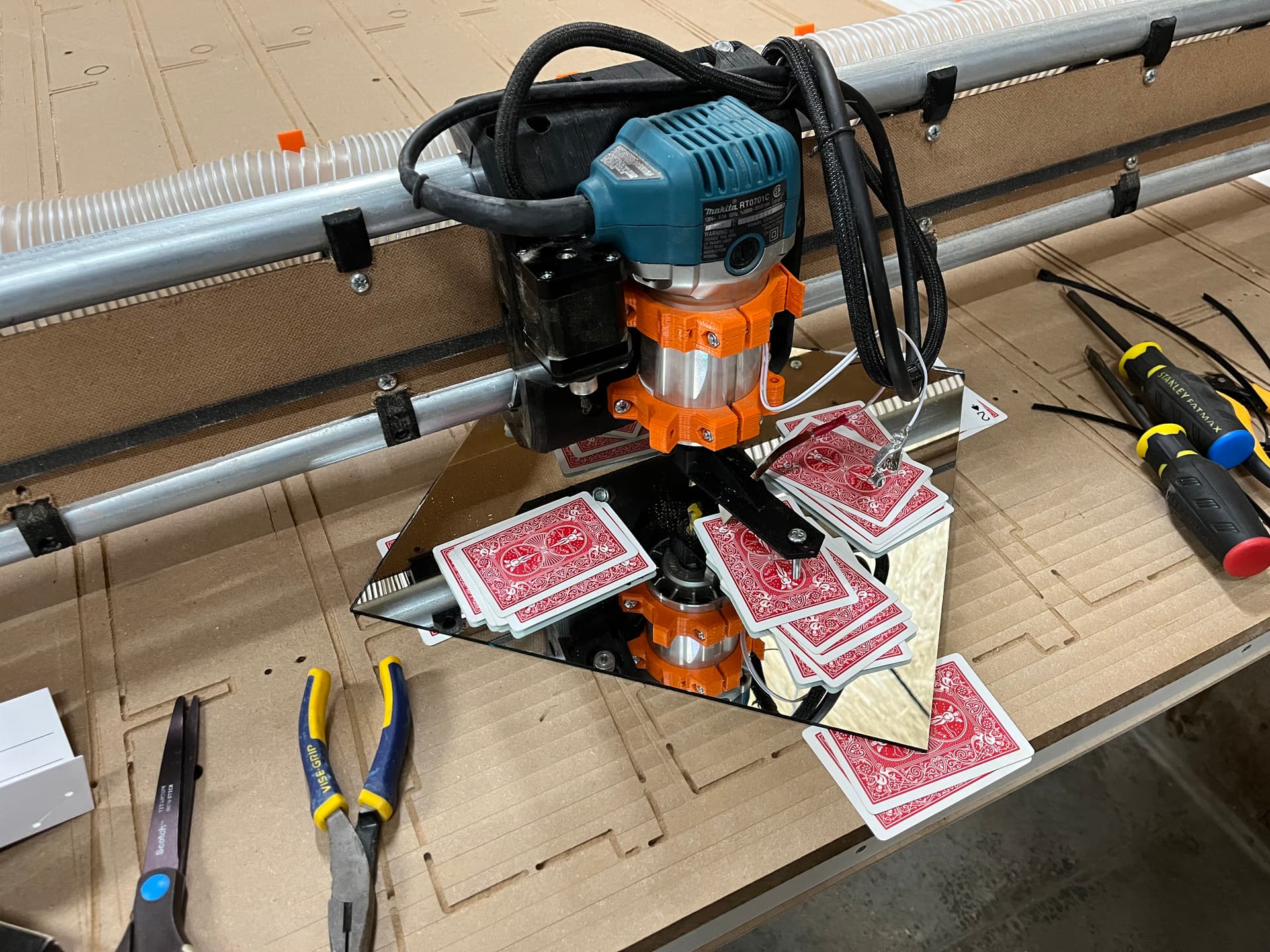
To tram I used RobP’s post as a guide. A mirror and some playing cards is all it took. I used playing cards to measure instead of using a dial indicator.
- First I printed a tramming tool for my router
- Second you grab a deck of cards and a known flat surface. I used a 12x12 mirror I had from 3D printer build surface.
- Level the mirror to the tramming tool using cards underneath the mirror. Note to keep tramming tool rotated in the same direction when leveling the 4 corners
- Center the router on the mirror and rotate the tramming tool and measure the gap between the tool and the mirror at the X and Y extents.
- For me +Y needed 3 cards, -Y needed 8, -X needed 7 and +X needed 5
- I shimmed the top router mount forward using multiple pieces of card stock.
- I shimmed the between the router and the mount to rotate the router CCW
My plan is to do a 1.5mm rough surface and then a .5mm fine surface to get the table where it needs to be. More on that later.
I also fed an air line through to the tool head for future air blast if machining aluminum or plastics.
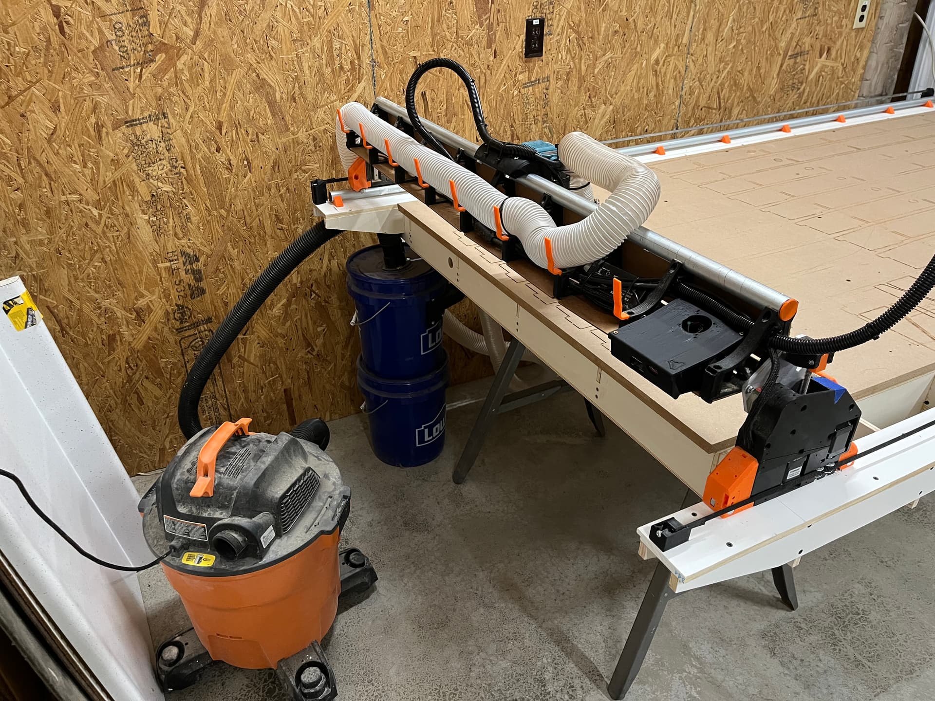
Lastly I cleaned up my electrical and mounted the jackpot control box. Here you can see my current dust collection setup. The vacuum has a filter bag in it which improves the filter life by about 1000 times.
I will probably forgo the swapping of X and Y. The worst of my table’s smile is on the +Y end. If I were to make the swap I would have to work with that issue more frequently. I still like the idea but probably won’t do it unless I build a new table that fixes my mistakes…
I am also re-thinking my electrical plans. I want to be able to easily take the gantry off the table and cable chain definitely complicates that. Taking inspiration from @orob’s pics above,I will probably make everything gantry mounted and go with the pendant over physical buttons for feed hold, start, and probe
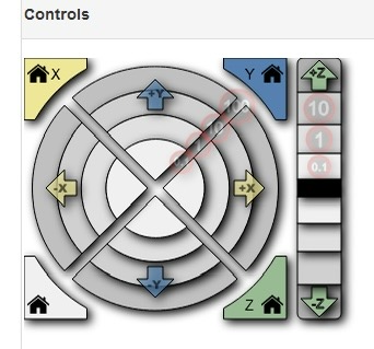
I’m not sure if I mentioned it here or not, but I had a lot of problems with the “controls” section of the FluidNC web UI not working for me. It was apparently the iPad that I was using. Now that I have the table built and I’m not on the floor, I’ve switched from the iPad to an old linux laptop. The UI seems to work fine on that.