Smaller offset would help, the idea is super solid though and I love it. I have no issue with tape but…this is very clean and dare I say, Professional solution.
3 Likes
I wonder if the tolerances required are good enough for a wide variety of printers? Having said that - my Camlock Vac fitting has been downloaded 4000 times and the tolerances on the cam are somewhere between “not much” and 0.1mm and there have been no negative comments to date. I think with this already being a split ring, 0 tolerance will work as long as they are printed in the same filament as the mounts.
That’s what I thought but couldn’t get a solid answer, thanks ![]()
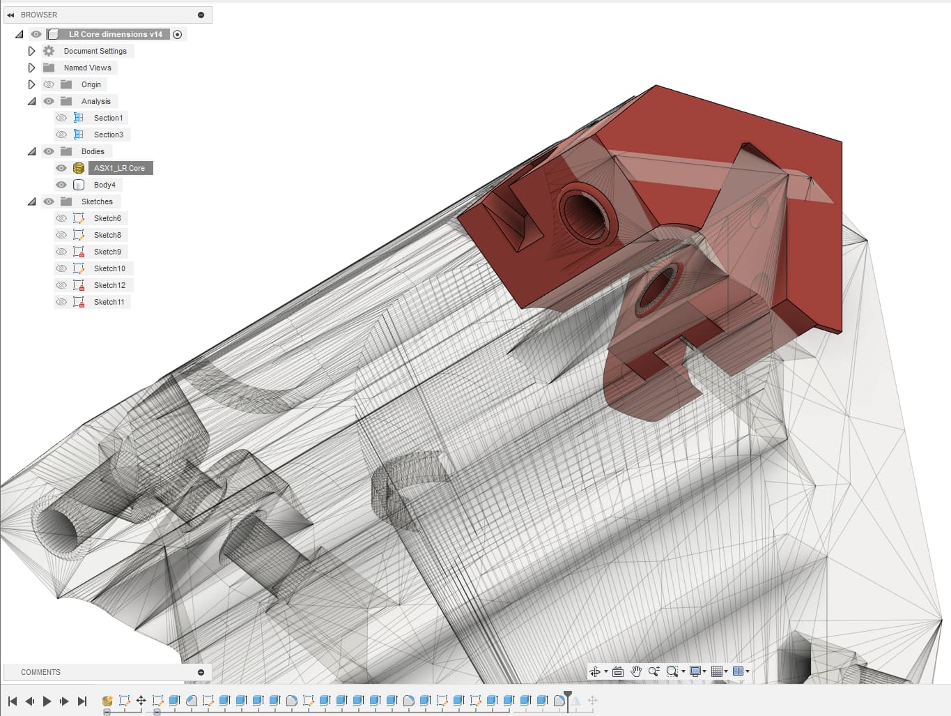
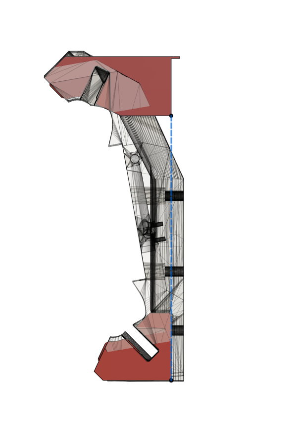
As far as I tried, it seems we’re running a bit out of space
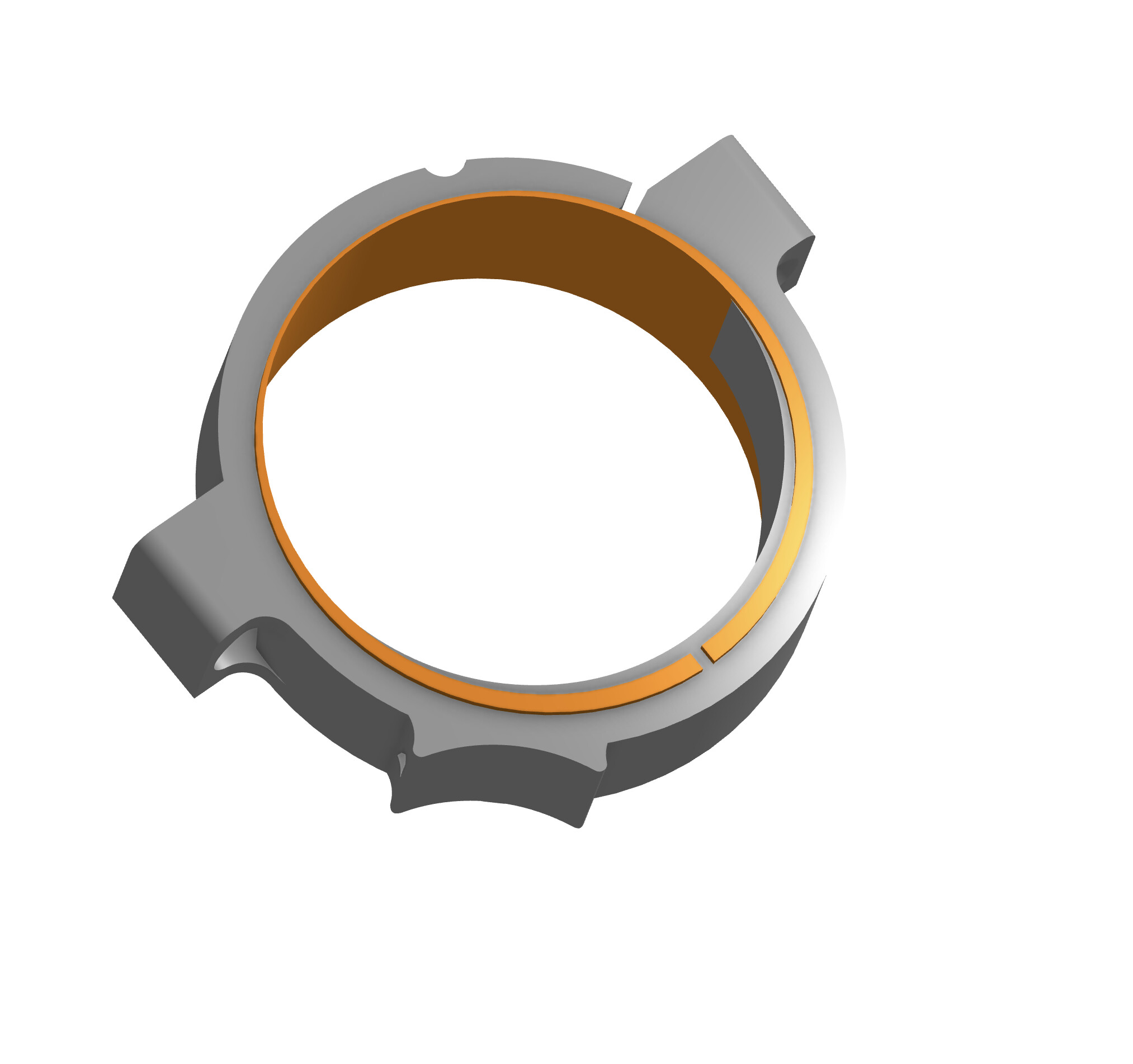
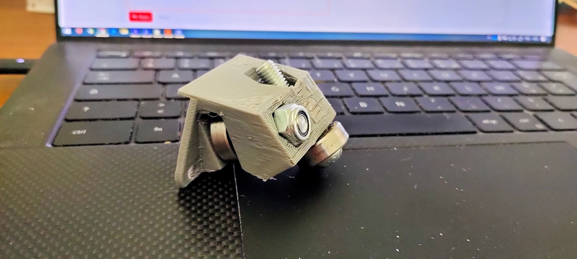
The “cam ring” is very thin on one side
From the dry-fit I tested, it seems to warp quite a bit
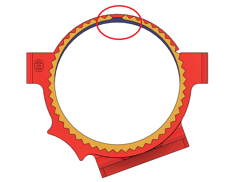
So, either I find a way to further the brace’s thickness (but this one too could get too thin), or I try to fix the cam ring by moving the open slot to the thicker side , see if it helps…
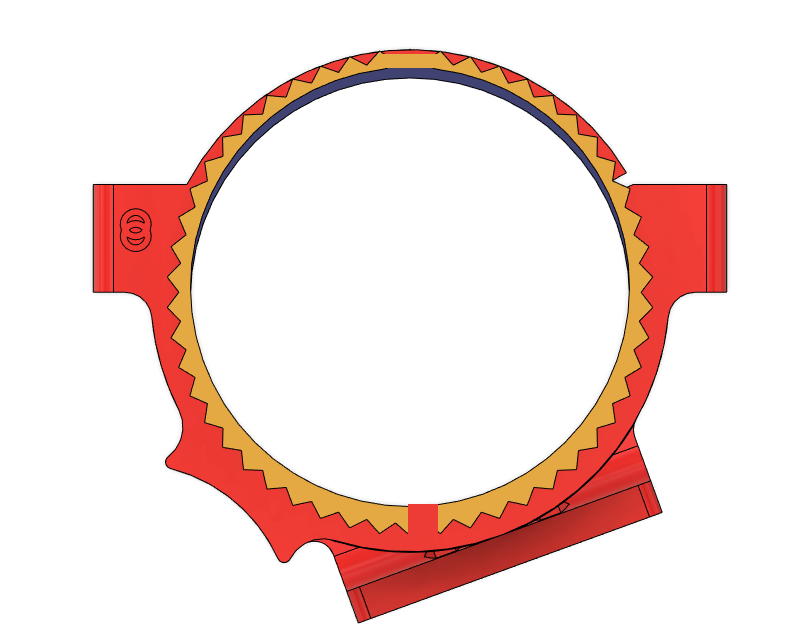
Making the slot on the thicker side makes sense. It looks as though you’ve made the “mount ring” a cam as well? That shouldn’t be necessary.
I seriously don’t think I can have a crack at it for a couple of weeks (will be away for a week starting in a day or two) but I’ll try to get to it.
That’s one of the things I discovered along the way, Ryan’s original design is already a cam ![]()
I think this is the way you get the router to "lock-in"when tightening the bracket
Another way I could get away with this would be to move the router a little bit forward, but that’s quite a bit more complicated design-wise, and I’d still be limited by the space available on the sides
I’m more and more tempted to have some kind of “flat core”, with just a simple flat front piece instead of the curved one…
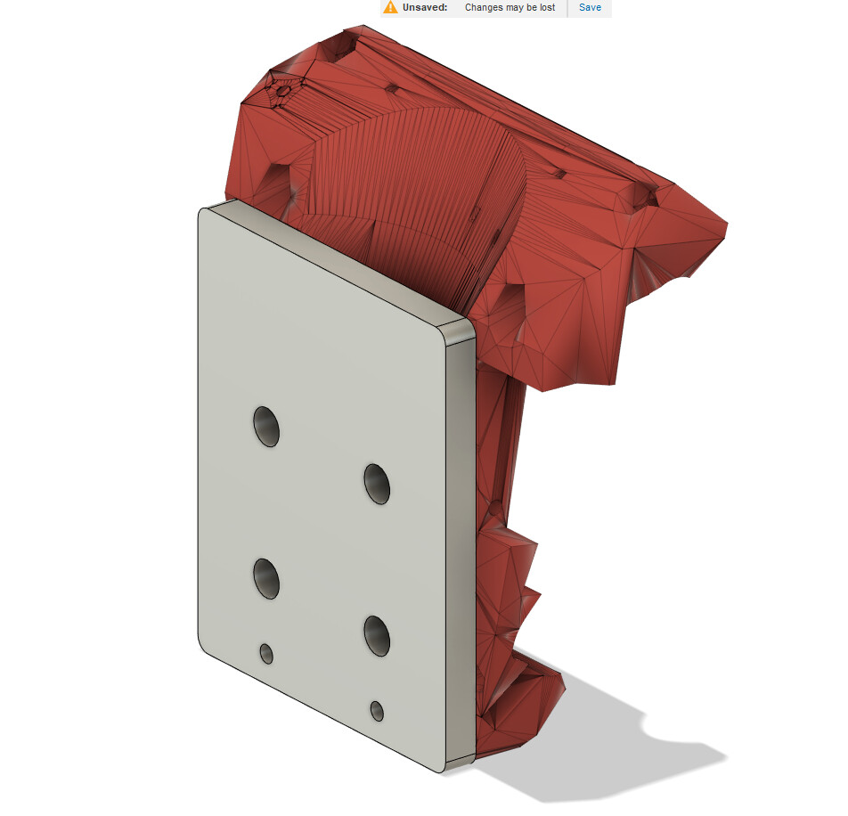
Maybe even a milled front face, and rollers attached to the back… (this would also probably help with the challenge of printing this large part)
This wouldn’t be as “elegant” as the current design, and would probably waste some space on the Y direction
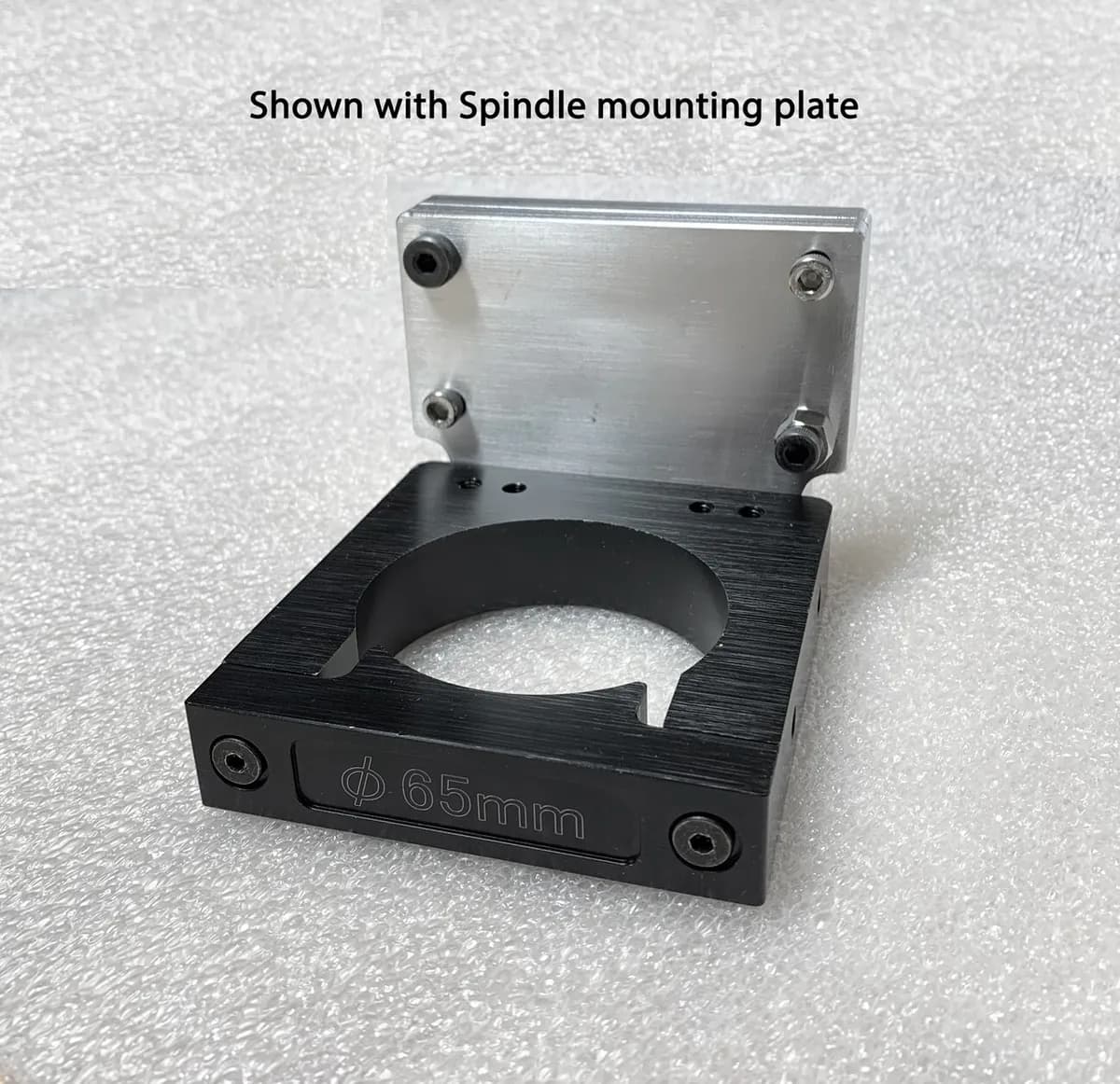
But this should be a lot more flexible, even opening up to using some “standard” aluminium clamps with traming plates
eg:
The front plate could event be made in aluminium if need be…
I don’t know the distances and angles between the railes and rollers though, and that’s a bit hard to measure…
@vicious1 is there an equivalent to this diagram, but from the side?
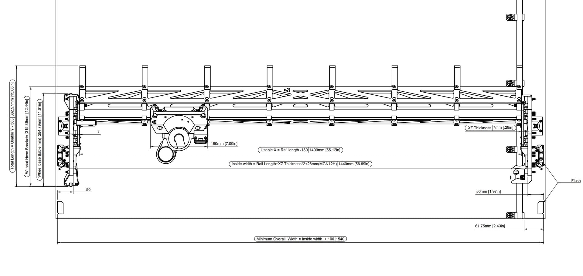
No, the tool mount is a 65mm diameter circle which tightens against the core to constrict the router.
The shape has to change slightly to work with the existing core. It looks a bit in plan but in 3d it’s not a terribly big deal. In the diagram I’ve moved the centre of the tool over by three mm which only moves it by 1.5mm because the new diameter is 68mm. (these numbers will probably reduce somewhat after testing)
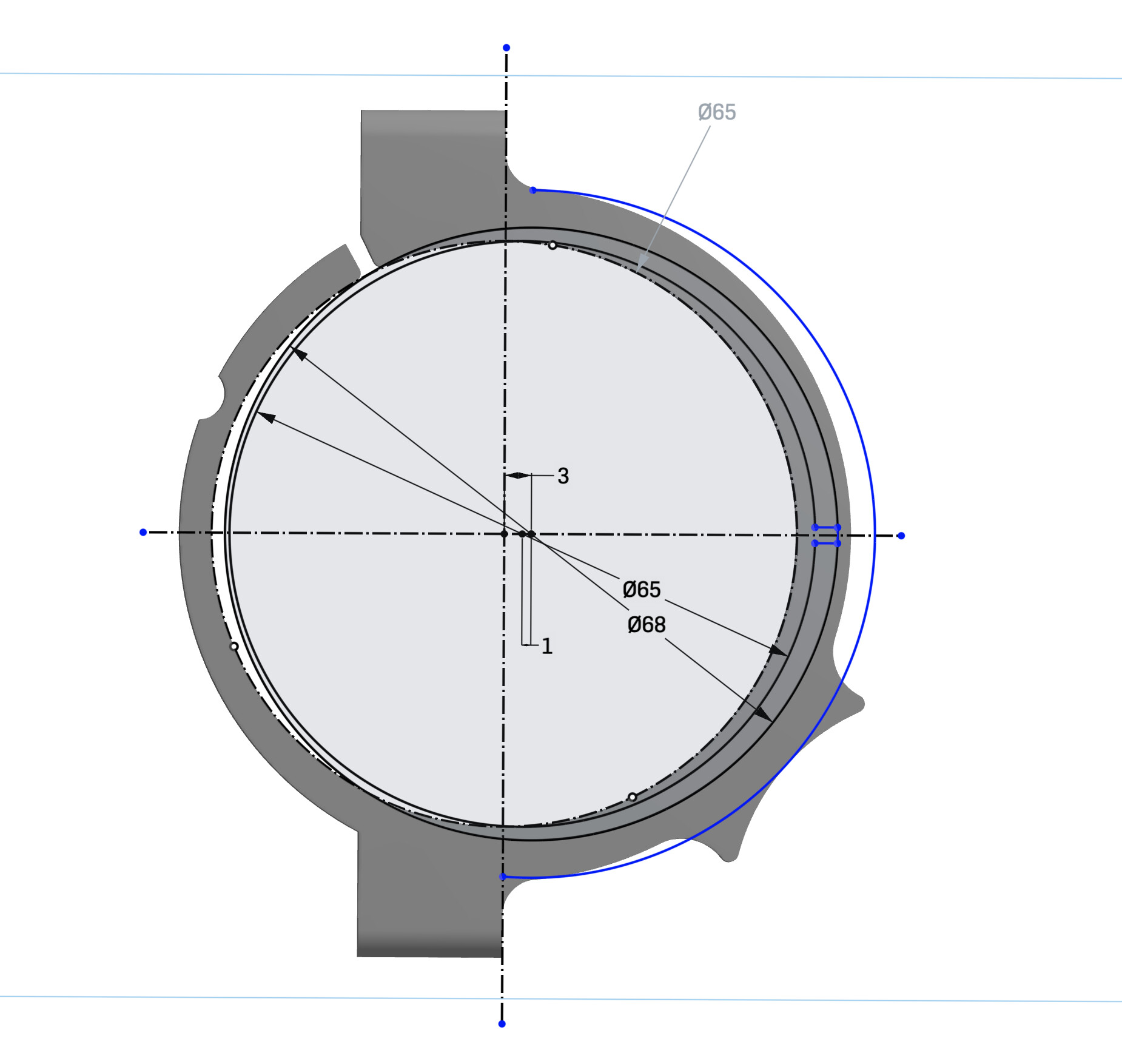
This would have been clearer if I’d cut out the bit in the centre that we don’t need - but you can get an idea of the new mount proportion, it’s very close to the original (although I haven’t moved the vac mount because I think it will clash with the line of the screw!
I would love to have a couple of hours to refine it for you, but that should be enough to go on with if you still want to try.
EDIT - here’s a view with that internal bit removed.

Yeah I need to give this a bit more time in design, I whipped up something quite quickly and I think I’ve made quite a few mistakes here and there…
I must say the cam shape has always been a challenge for me, I need the excentricity to be “exagerated” to really wrap my mind around what it does and visually apprehend it… and with the tight space we’re working with here, I’m sometimes a bit lost ^^
Yes you can tighten the left or right to also tilt it slightly left or right as well. When I put a new one on I tighten the left side of both all the way and just snug the right a bit. If I need to tilt I will adjust teh top one for the largest effect.
There is a huge downside to moving the router out…leverage. The weakest point of this router is tilt and that will significantly make it worse. I think a major flaw on a lot of other designs is how far out they mount their routers, this is the most compounded axis and needs to be the tightest. They insist on mounting steppers and bearings behind the router when it should be to the side to decrease the lever arm.
Not super clear on what you are asking, maybe take a screenshot and I can give you a dimension.
2 Likes
If I made a slightly larger core with the mounting holes a bit further apart we would have more room to work. Adding to the notes for a LR3.1
5 Likes
Yet we also asked for a slimmer core for idex builds ![]()
Ah… Can’t satisfy everyone… unless we separate wheel brackets from the face plate and then anyone can customize the face plates width? ![]()
1 Like
Use 4 tubes and have back to back cores front and back. ![]()
“Double IDEX” build! ![]()
Having a third tube in the back could be useful though… have the core mounted horizontaly under the gantry and you can make holes on the side of the boards for dowels in cabinetry
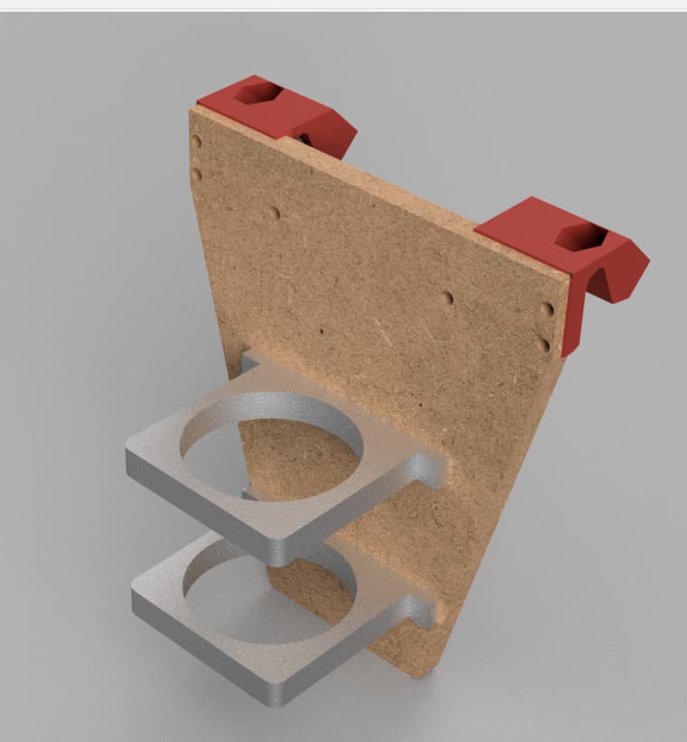
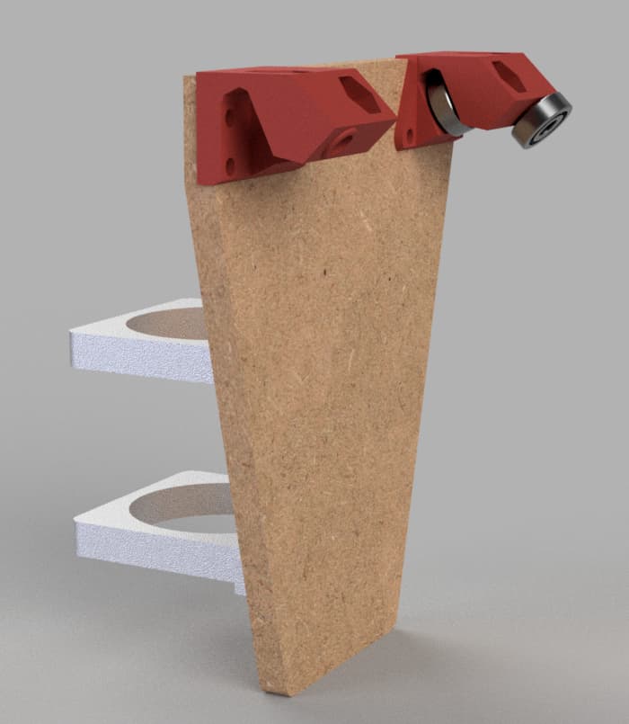
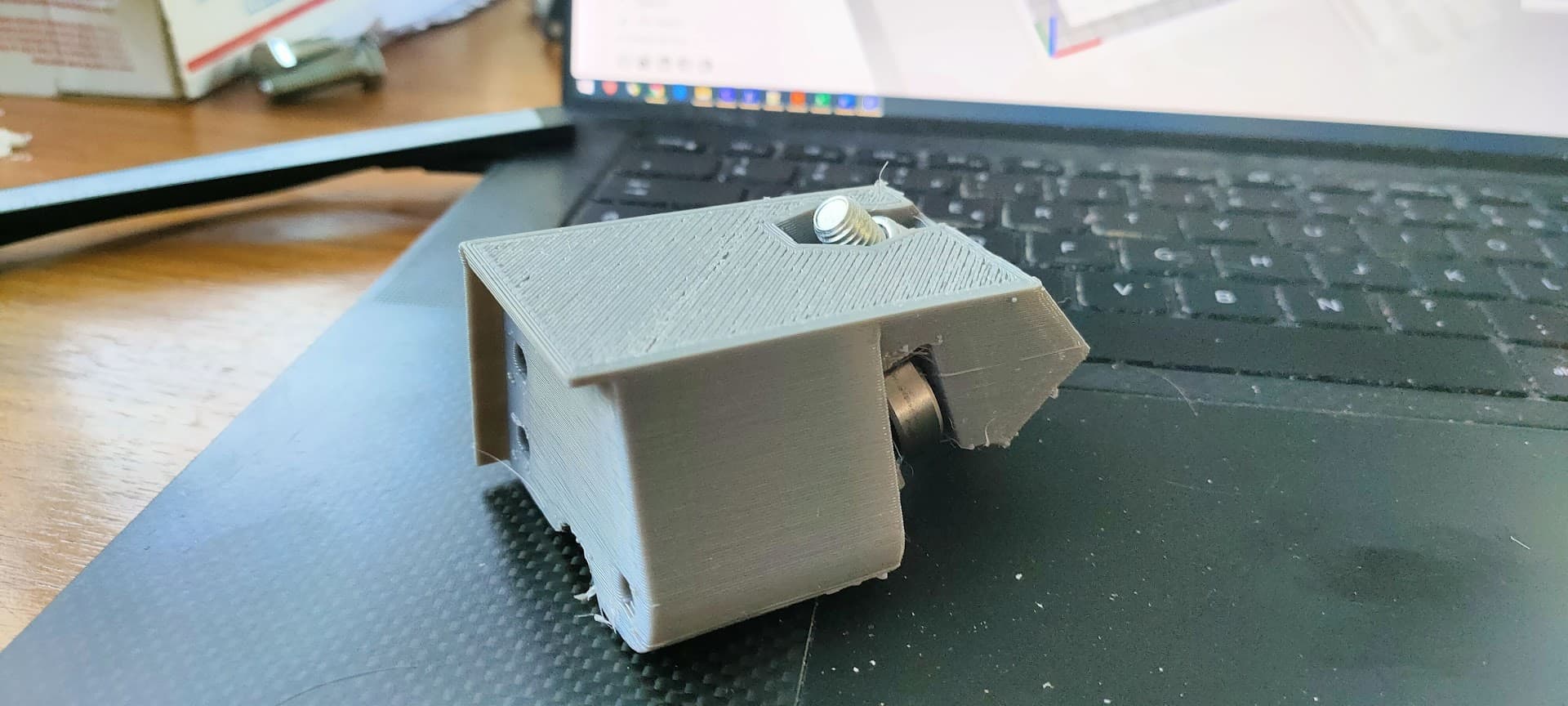
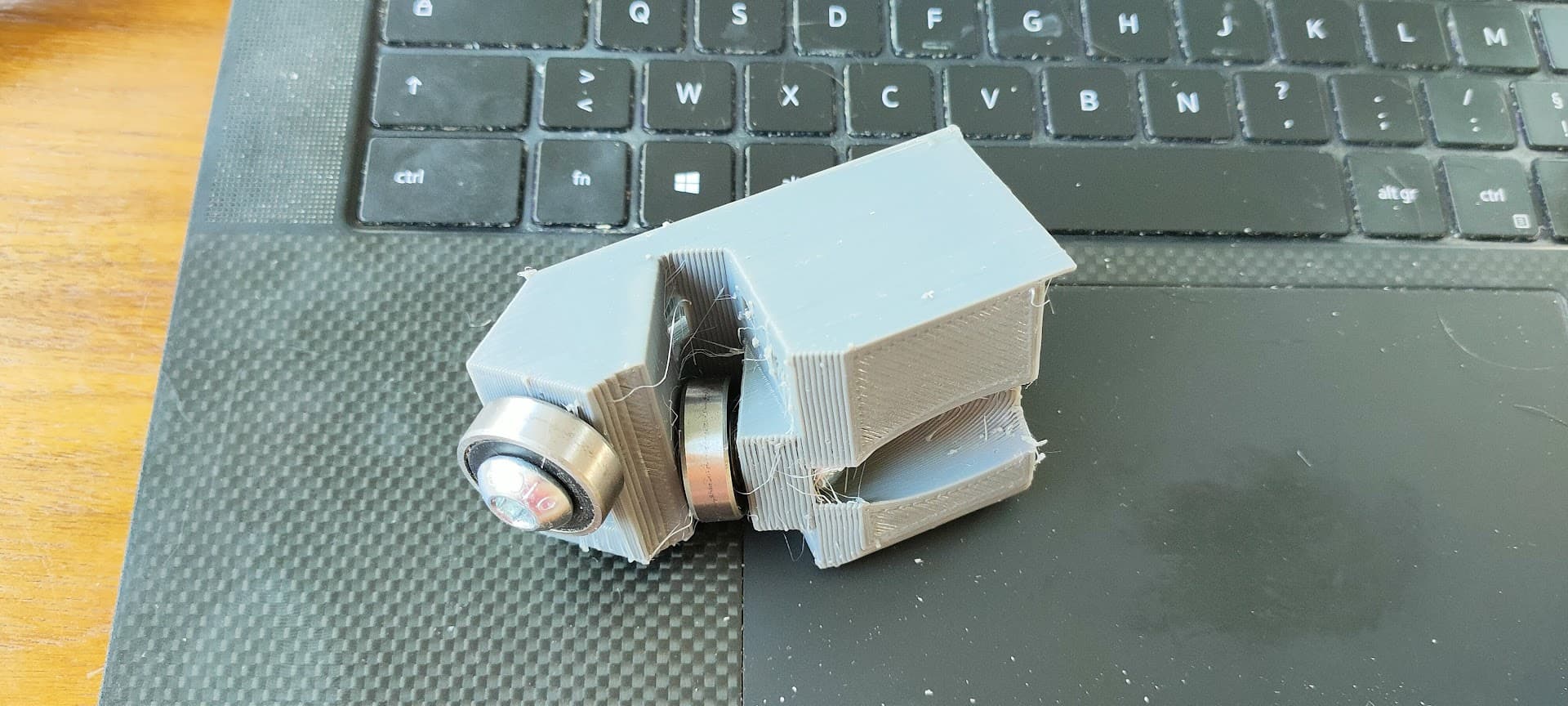
First prototype printed, there are a few adjustment here and there but it seems to fit quite nicely on the rail…
I think I nailed the dimensions on this one ![]()
I’ll adjust the offset of the top of the plate later, I think I’ll use some shims for testing for now…
I need to design the bottom one now…
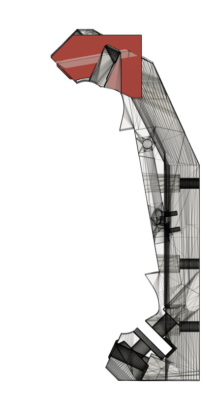
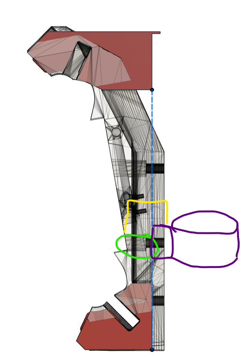
The beam is tilted, so something is still going to need an angle to make the router perpendicular.
The way you currently have it cut it will intersect with the beam.
I added the offset to the top piece while designing the bottom
It’s still unfinished though… have some details to add…
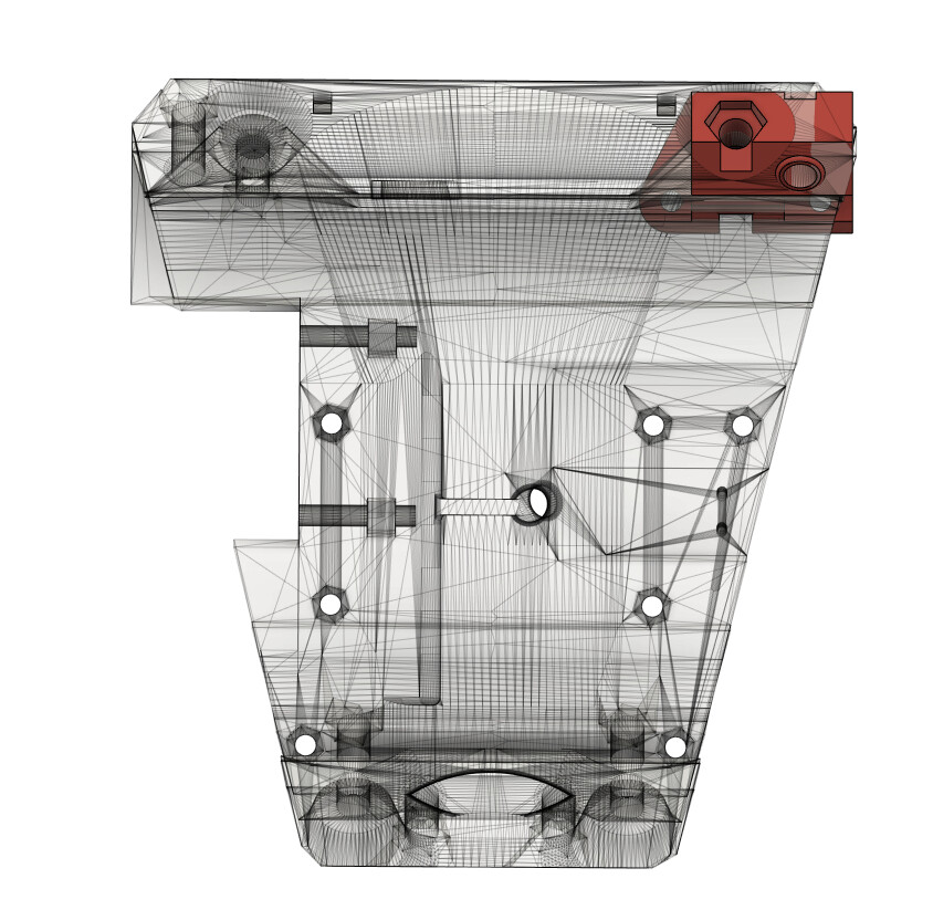
Does this look better?
1 Like
Yes but the yellow is the distance you are pushing any tool out from where it can be stock.
What is the main goal of a flat plate?
you will need to mount the end stop and the stepper as well.
Seems like it would be a better idea to use my tool mount cad and just make a flat tool plat that bolts one to the factory holes?
1 Like
Trying to see if I can make some sort of “prototyping” plate, just a flat blank face for easy tinkering and mounting stuff…
This would also provide a few “out of standard” possibilitie and niche advantages :
- narrower/wider core by adjusting the face plate
- more conventional mounting for off the shelf accessories (eg using an aluminium clamp that’s been provided with your spindle, or a tramming plate)
- faster/easier print
Why not even crazier things like a tilting plate, quick change plate (put a dowel in the first palte and slide in new tools already attached to a quick change plate), rotating tool changer… or any other exotic/uncommon setup
Nothing wrong with the original design, it’s brilliant and packed/optimized
But that’s the point, it’s optimized for a a specific use case and I appreciate some flexibility when I’m tinkering ![]()
That was the plan… At first ![]()
Then I thought “Hey why not try my hand at designing this from scratch?” in an attempt to reclaim a bit of the wasted space you showed in yellow ![]()
That’s in the bucket list…
Do you have the height measurment between the top of the core and the belt/Switch by any chance ? ![]()
I can check this evening if you can remind me later.