Give me ten minutes! (Living in a fully metric country that sells 1/4" and 6mm bits gets super confusing but I have 8mm collets too!
2 Likes
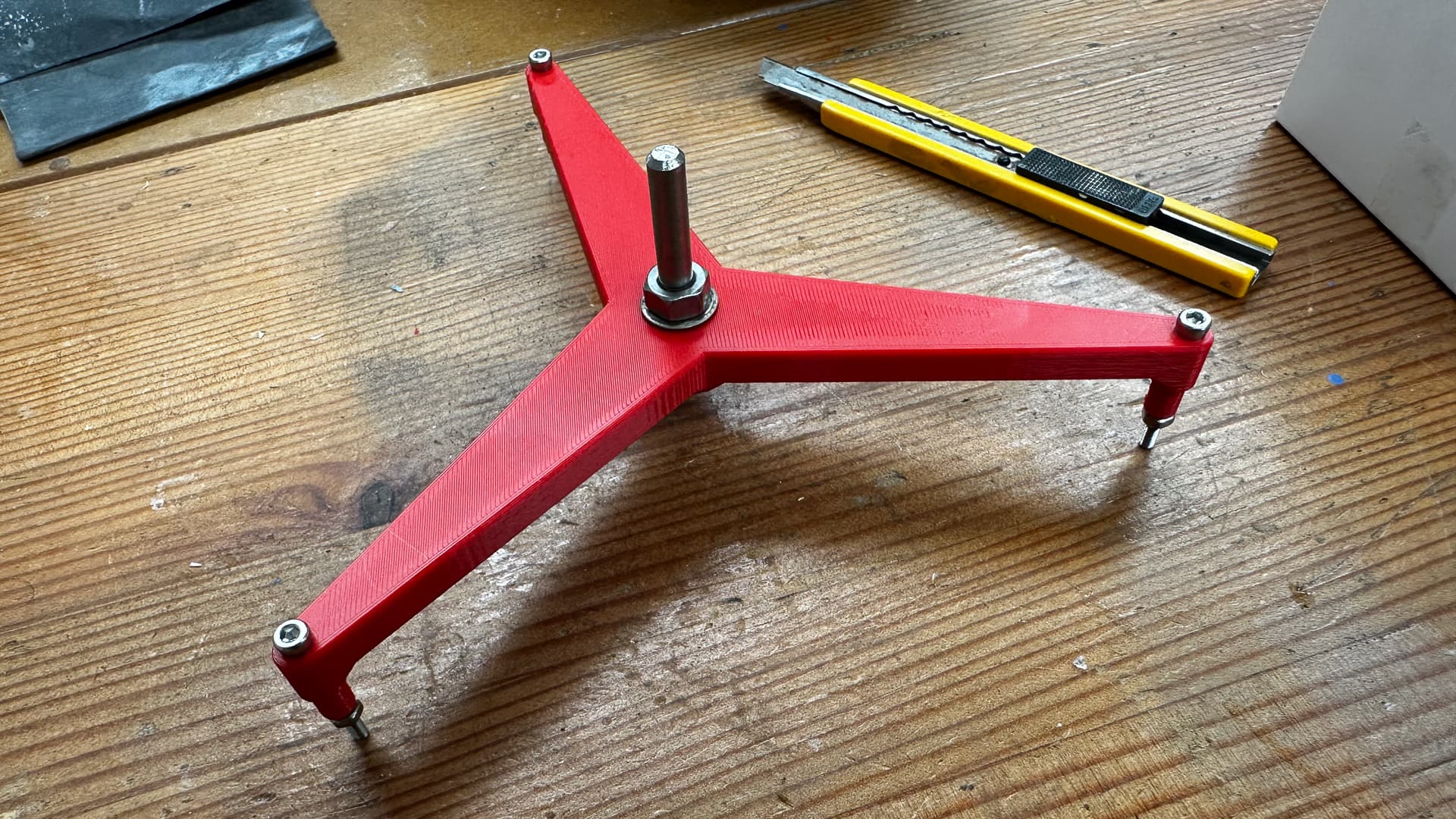
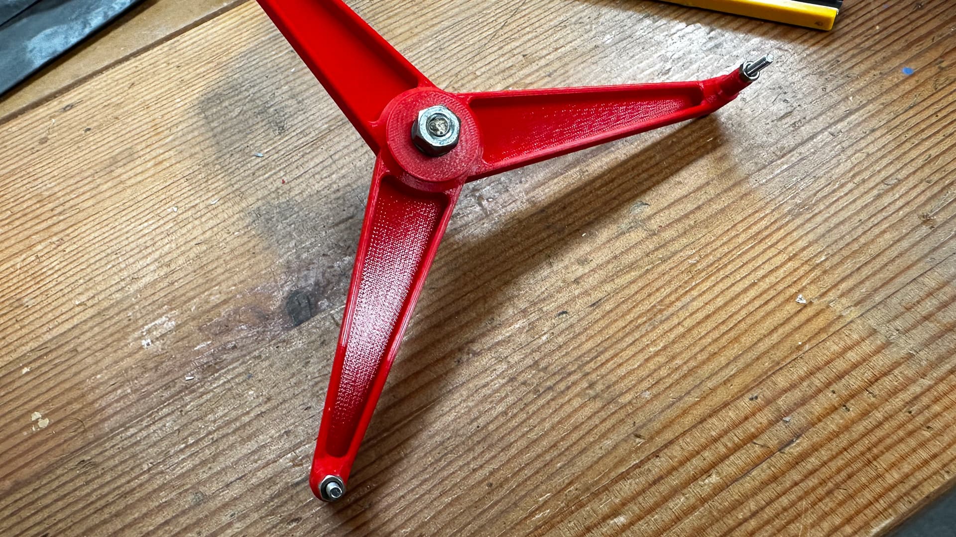
I hope you wanted a red one!
It’s in the post with the other one now.
2 Likes
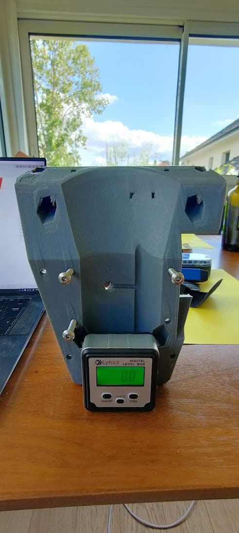
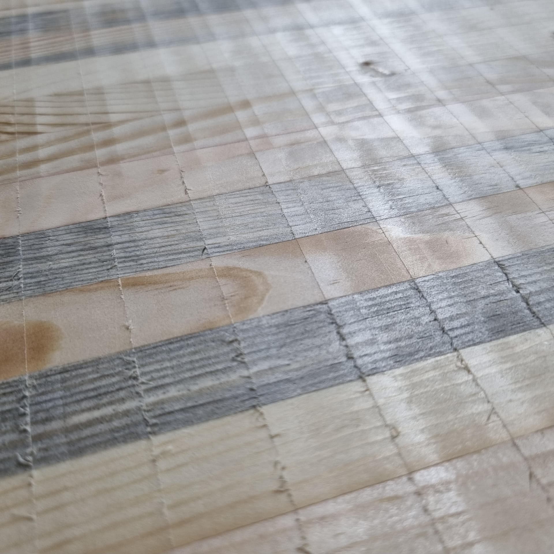
.45 layers with a .6 nozzle, not the prettiest thing, but it gets you there… and quite fast…
It’s very hard to measure though
The geometry of the core doesn’t make it very easy to get a good reference reading >_<
I think it’s pretty ok nonetheless…
5 Likes
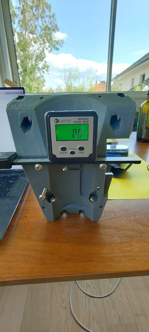
Just run some diagonals from the mounting bolts you have inserted, and do a double check between the top two and the bottom (vac base) mounting bolts.
That will give you an idea of how out of square it is (if it is) and you’d easily be able to draw some rough 2d drawings to nut out what that translates to over the full height.
1 Like
Looks awesome!
Have you seen…

not sure that makes sense ![]()
If your desk is slightly off where to core sits you´ll measure that error too, no?
Think Peter´s suggestion might be the best one.
if anyone wonders, that error margin gives the following result:
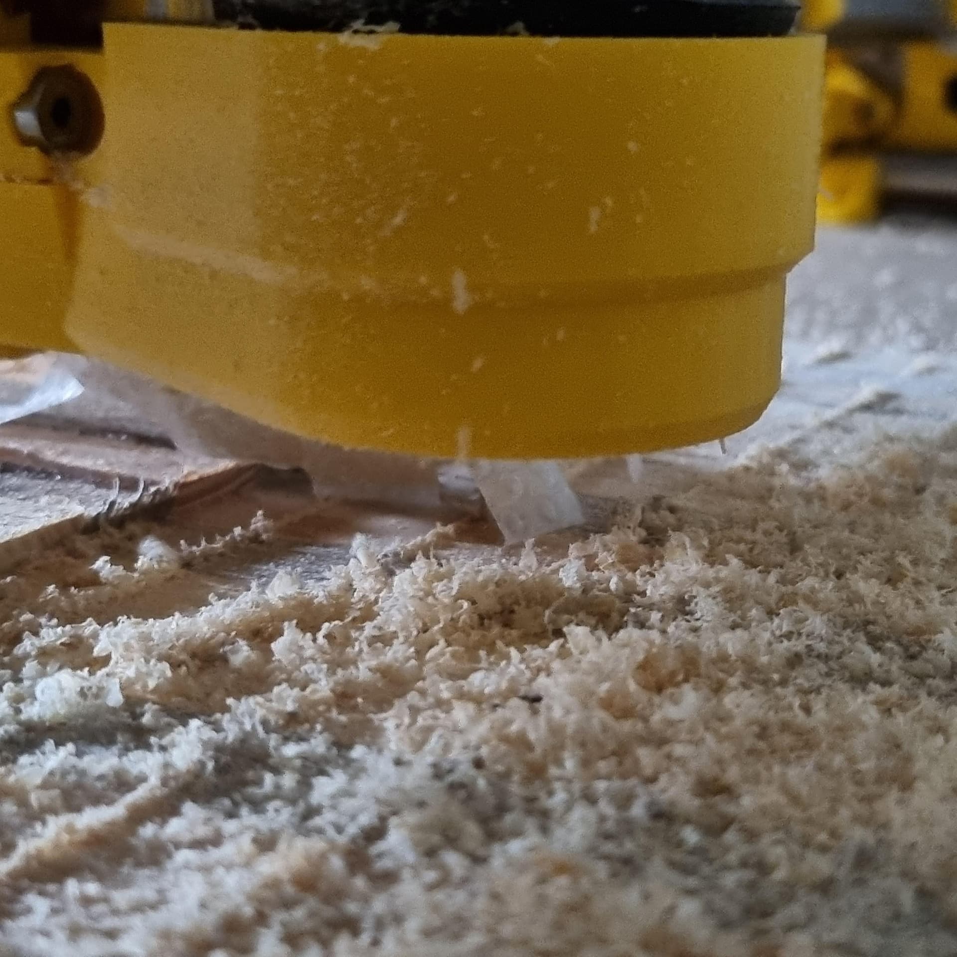
Not sure what causes the “hairs” since I took 70% stepover. When cleaned it is just a hair thick. Adding an additional piece of tape in the Y direction gives the following result:
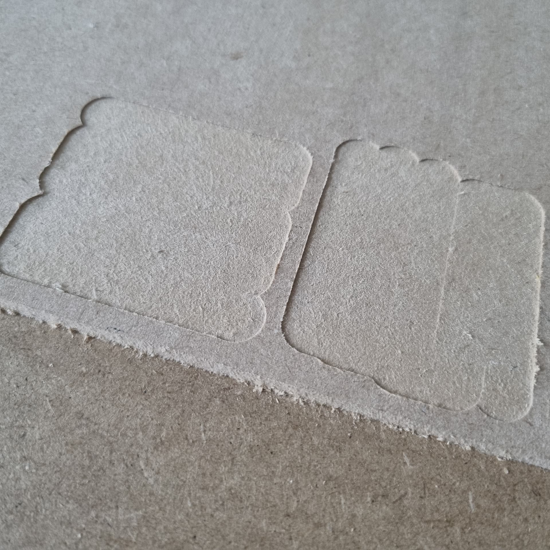
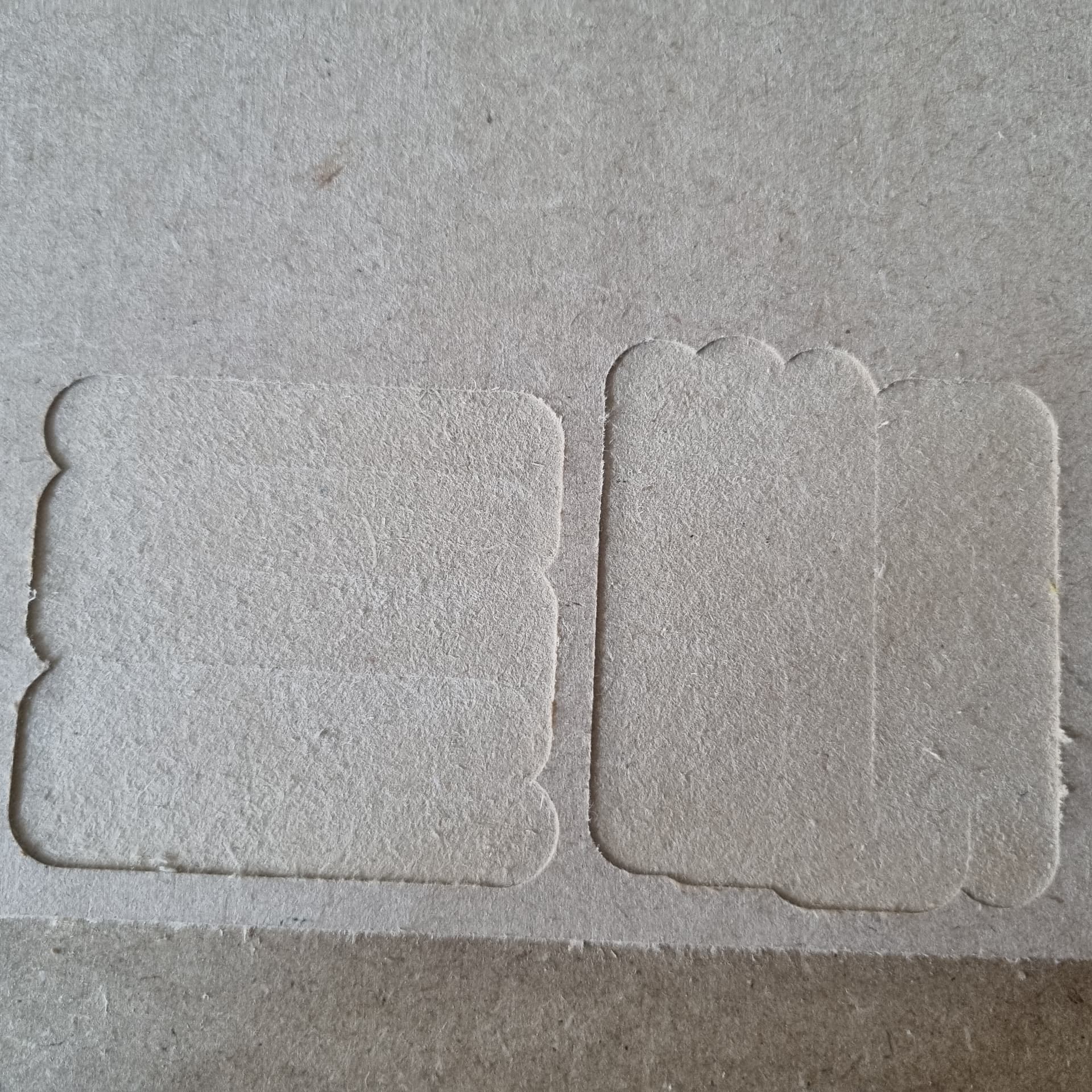
There´s still a faint line (visible depending on the angle you´re looking), will be hard to get that one gone since thare´s also runout (is it called that way?) from the router too…
Hope you can get to that error margin with your new core!
2 Likes
I’m supposing if there’s an error along the Z printer axis, it’s constant
So what I’m checking is that the top and bottom are parallel (and si thé core should be perpendicular to the rails) and that the mounts are 90° + parallel to the top/bottom
Did the measurments on the diagonals they seem equal but I need to re-do this with the bolts on
2 Likes
When I got my engine block and cylinder head surfaced at a machine shop, you could see the lines between passes of the mill, and I doubt they have any tramming error on their machine. What is visible to the eye can be still impossible to correct for on a cutting machine.
So, I think you’re fine.
I still haven’t really trammed my LR3. I did do my Primo because it was a bit excessive (about the same as yours) but havent really tested the LR3.
2 Likes
Heart transplant has been conducted successfully…
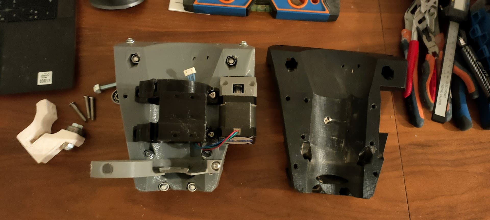
Not really a pleasant process, but it’s done…
It’s been a long long day though (try home depot + furnitures store with two kids one day…) so I’m not going to test it just yet… heading bed right now ^^"
6 Likes
Today is Parent Independence Day here (first day of school). I’m excited to see what I do with all this uninterrupted thinking space.
7 Likes
That makes sense! Thanks for the clarification.
True! But still, wanted to be as close as I can. For now I´m good, but the next day I´m bored I know what I´ll be doing ![]()
1 Like
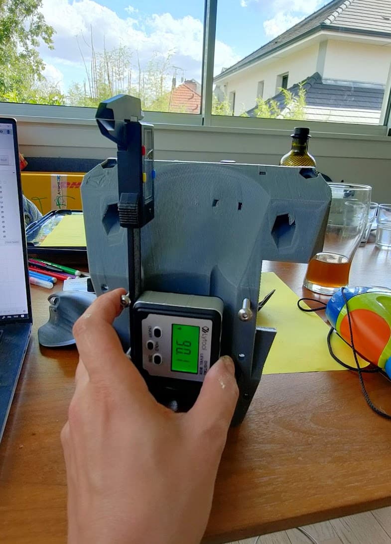
Banana coloured object for scale. ![]()
It looks as though it could work - Use three to get visually close, mark one leg and rotate to use as the final level measure.
4 Likes
I would make that the step before the final one.
Because the final one would be milling some test patterns and adjust if needed ![]()
As always: wonderful print!
2 Likes
I think we’re ready for the next step of this project, if I ever get my LR3 to run true again ![]()
Didn’t have much time to re-install the core the last few days…
but mayyyyybe I can get some motivation:
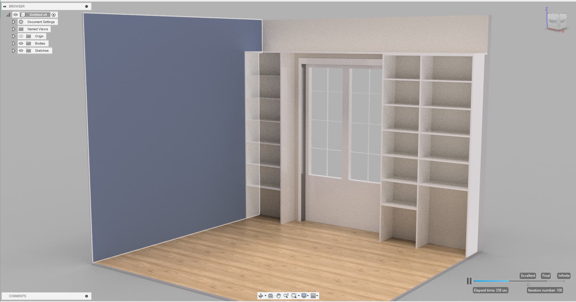
Still debating if I should put this on the LR3 or just use my “ol’trusty tenon jig”…
Or maybe just drill the system32 holes with the cnc, and keep the tenons old fashioned?
The tablets and sides will be 16/18mm particle board, 30cm wide and just cut to lengthes, so I won’t cut the panels out of a full sheet anyway
3 Likes
I’d say, cnc!
Would tape the wood just to make sure it cuts clean.
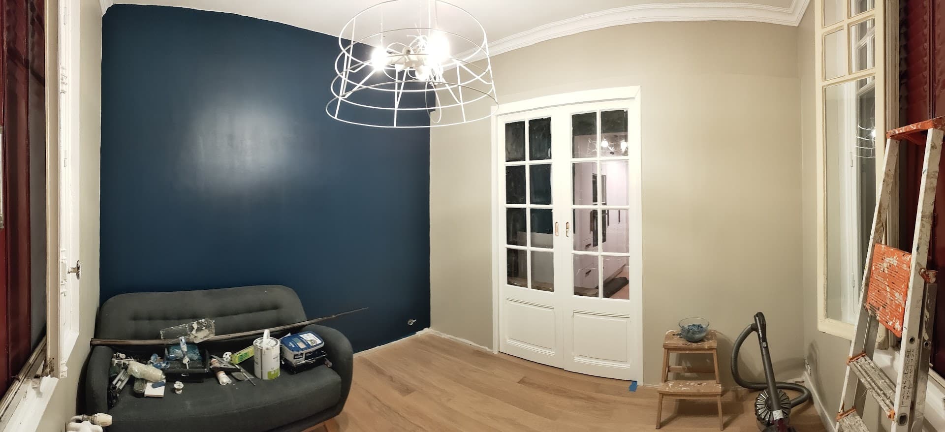
Just not sure if it is a good idea to put the cabinets around the door. Wouldn’t that feel cramped?
No, it’s fine, I’d be tempted to run a shelf or two above them though, and build a small chair-ladder to access them! ![]()
Those adjust cams are amazing. Freaking perfect.
When you put that new core on, the core itself can also be tilted. The two adjusters on the bottom will cause tilt in the X direction. Put the core so the top bearings are equidistant from your braces, then check the bearing tension with your fingers. Both should be exactly the same. Mess with the bottom tension to get them the same, slight tension, too much and you will bend the rails and your tram will be all over the place.
4 Likes
Have you tried them too? I thought @Fabien was my crash test bunny! ![]()
![]()
1 Like
No, but I think they need to get added to the next version, since most people do not like the tape shim method.
3 Likes
I think they need a tiny bit of experimentation - that first concept was to overcome a large out of plumb problem - might be quite touchy to use (which is why the triangular tramming gadget - just to give a feel for what’s happening.
I am loathe to suggest all this stuff without trying it first, but another nice thing around here is that everyone’s game for it!
2 Likes